CSD - Depth, Altitude, Draft, Pressure, SV Systems

Underwater Sensor Definition

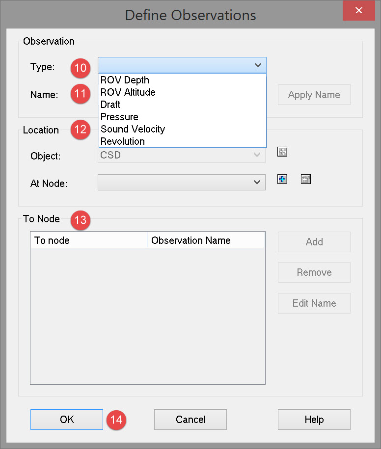
The following observation types can be defined:

  • ROV Depth (which despite the name does not necessarily apply only to an ROV)

  • ROV Altitude (which despite the name does not necessarily apply only to an ROV)

  • Draft (Draught)

  • Pressure

  • Sound Velocity

  • Revolution

CSD_DbSetup_NewSystem.jpg

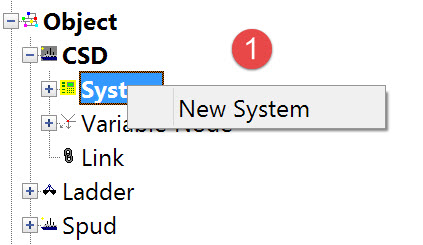
image2016-1-29 15:51:48.png Add a new system by selecting “Edit” from the menu bar, and then “New” and “System”, or right click on the item System in the item tree.

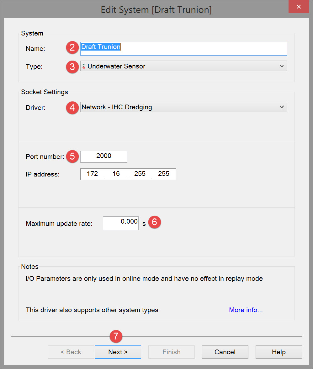
The following dialog opens. It is the first page of a wizard that steps you through the system definition process.
DBSetup_EditSystem_Underwater_P1.jpg

image2016-1-29 15:54:19.png Enter an appropriate name that provides instant recognition in Online displays.

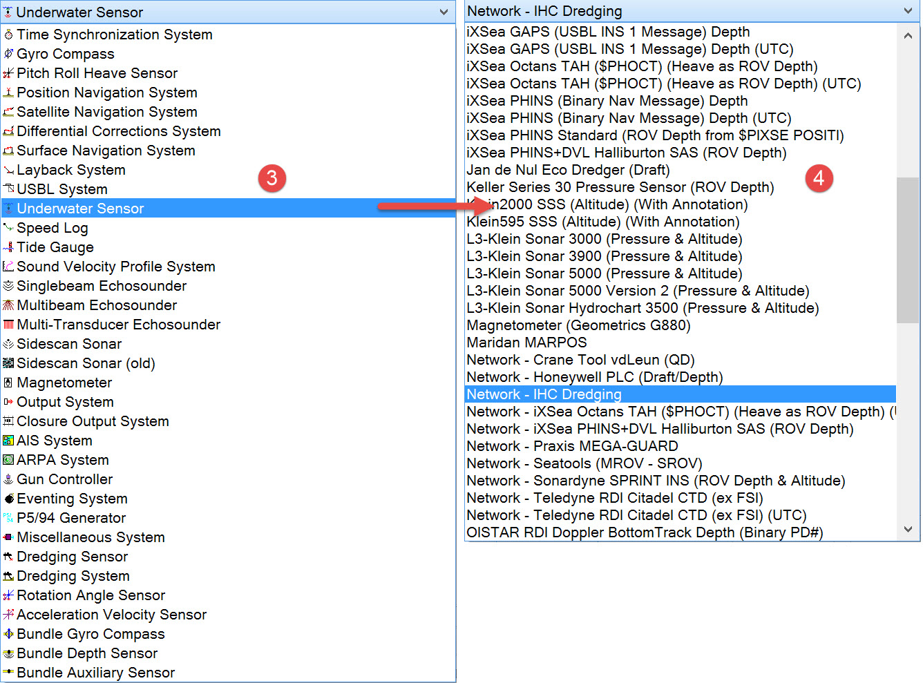
image2016-1-29 15:54:43.png  Select Underwater Sensor from the drop down list.

DBSetup_EditSystem_Underwater_TypeDriverList.jpg

image2016-1-29 16:1:32.png From the drop down list select the driver that corresponds to the data message output by the system to which QINSy is interfaced.

Note that the interfacing can be either serial or network so make sure to select the correct type.

image2016-1-29 16:2:51.png Enter interface port parameters.

Please refer to A Note on Interfacing Parameters.

image2016-1-29 16:5:30.png  Enter the data update parameters. Depending on the driver selected one or other, or both, these parameters are shown:

Updates

Maximum update rate

Enter a value to determine how often data will be decoded by the interface driver. Some equipment is capable of outputting data at high output rates, but it may not be necessary to use each update. A sensor system may for example output values hundreds of times per second, where five times per second is sufficient. In this case, enter a value of 0.20s. Any data not decoded by the driver is lost and cannot be recovered later.

 Latency

Latency is the time between the actual measurement made in the sensor system and the time the data message arrives at the port. The time in QINSy will thus be the arrival time corrected with the latency.
Modern sensor systems will exhibit no latency, or will have compensated for the latency in the time tag of each data message.

image2016-1-29 16:6:12.png  Press Next to advance to the second page of the wizard which will look like this:

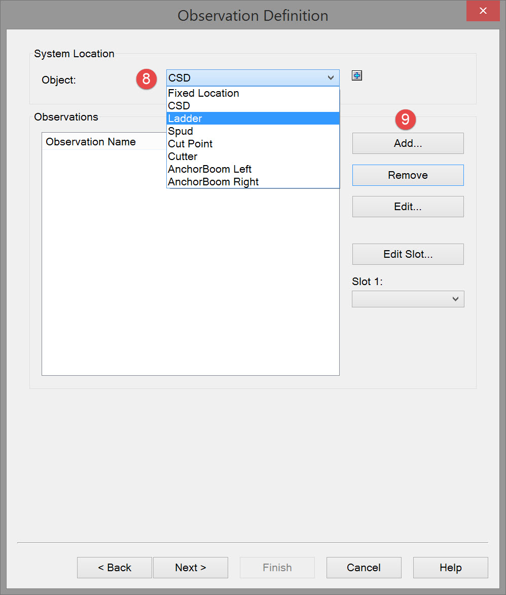
DBSetup_EditSystem_Underwater_ObsDefEmpty.jpg

image2016-1-29 16:22:4.png Initially the dialog is empty. Select the object upon which the sensor is located.

image2016-1-29 16:23:23.png  Click on the Add button which brings up the Define Observation dialog.

DBSetup_EditSystem_Underwater_DefObs.jpg

image2016-1-29 16:28:16.png Select the type of observation that is to be read from the sensor. Then enter an observation name.

image2016-1-29 16:30:27.png   Give the observation a name easily recognized when Online.

image2016-1-29 16:32:7.png  Select the object on which, and node at which, the observation is made.

image2016-1-29 16:33:54.png A To Node is not required for any of these observation types.

image2016-1-29 16:36:52.png Click OK to return to the Observation Definition dialog.

Return to top of page.

Return to: Cutter Suction Dredger (CSD) - System Definitions