How-to Anchor Handling
This document describes how to use Anchor Handling within Qinsy.
Anchor Handling is used to manage anchors and tugs on anchor handling jobs.
It is also possible to calculate and visualize the catenary shape of the anchor wires.
On this page:
Hardware Setup
For anchor handling the positioning systems and heading sensors are installed on the barge/rig and on the tug boats.
On the tugs a tug-display can be installed: this is a small program that runs without a dongle and shows where to go (to drop an anchor) and where the barge/rig and the other tugs are.
Qinsy runs on the barge. It is possible to install a separate Qinsy version on the anchor foreman’s pc. The Qinsy survey pc and the anchor handling pc are then connected to each other over a network.
A variation to this option are two barges, each with anchor handling tugs and anchors. The communication between the two barges must be done with wireless LAN.
A radio modem is used to send information from the tugs to the barge/rig and from the barge/rig to the tugs.
A setup with one barge/rig and two tugs looks like this:

When a positioning system and heading sensor are installed on the tug, use the SerialMux.exe program.
This program can be found in the Qinsy Console in the lower pane (if it's not there, click with your right mouse button in the lower pane and select Add/Remove QPS Programs).
With the SerialMux.exe program the positioning and heading messages can be combined to one message.
It's a small program that reads data strings from 2 or more com-ports and sends them out together on another com-port.
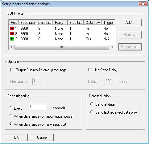
With the Add button a port can be selected.
In the Port setup the Direction determines from which ports the program should read data (in) and to which port the combined data should be sent (out).
Database Setup
Use the wizards of Database Setup to define a survey setup.
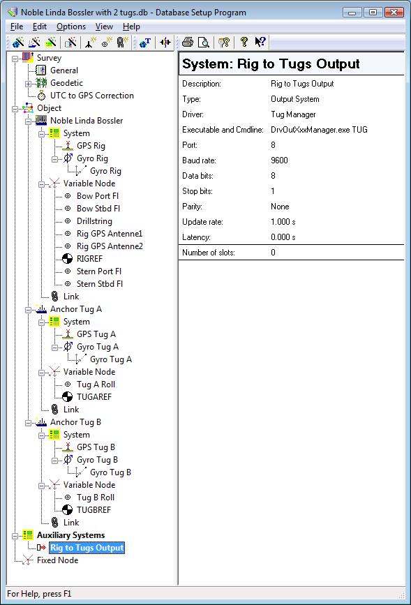
There are several objects in the database: a barge/rig and some tugs.
The barge/rig and each tug have their own positioning and heading system.
One Output System should be defined: the Tug Manager.
With this tool position messages from the barge/rig are sent to the tugs.
Line Planning
During anchor handling, the pick-up and drop positions of the anchors can be stored to a line database file (*.qgfline). Enable this option in the Anchor Planning dialog (Controller-Settings-Session Setup-Anchors-Anchor Setup).
Prior to starting the Controller, it is worth opening the Line Planning module, which leads to the Survey Manager (Qinsy Console-lower panel) and creating a line database file for your project which at least includes the “intended locations”.
If the Client has also provided the intended anchor locations, it is worth entering those too, as later they can be selected from the line database, for the anchor planning.
Online
Use the Computation Setup (Qinsy Controller-Settings-Computation Setup) to create a computation for EACH object as shown in the figure below:
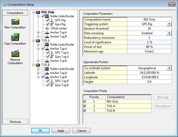
More information about the Computation Setup can be found here and in the F1 inline Help.
In the Online Controller select Settings-Session Setup-Anchors. This opens the anchor-handling menu.
Should the Anchor menu option not be visible, activate it through Settings-Session Shortcuts-Show Anchor Setup.
First do the Vessel Setup:
Vessel Setup
Select the “Operation Type”: One vessel (No Tugs), Multiple Vessels (Rig and Tugs) or Hookup Operation (Rig and Tugs) .
When this option is disabled, make sure previously assigned anchors are Removed from the Anchor Setup page.
In both cases a Vessel/Rig and a Computation must be selected.
Select the Number of Tugboats: Qinsy will look into the template database for the number of objects minus 1 (the Rig/Barge).
Fairlead Setup: the number of fairleads is the same as the number of winches. For each fairlead a (winch) node must be selected.
The anchor line will be connected to this point on the rig.
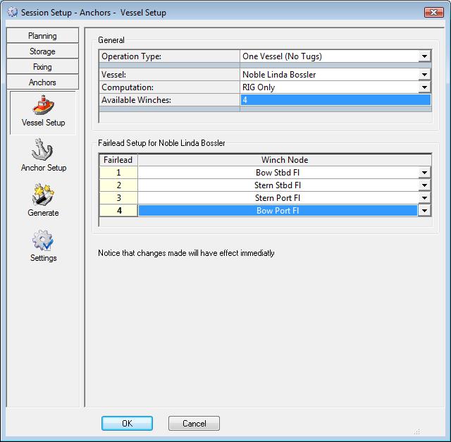
Typical Vessel Setup for one vessel
Tug Setup: the number of tugs is already defined and for each tug an object, a computation and an anchor roller node must be selected.
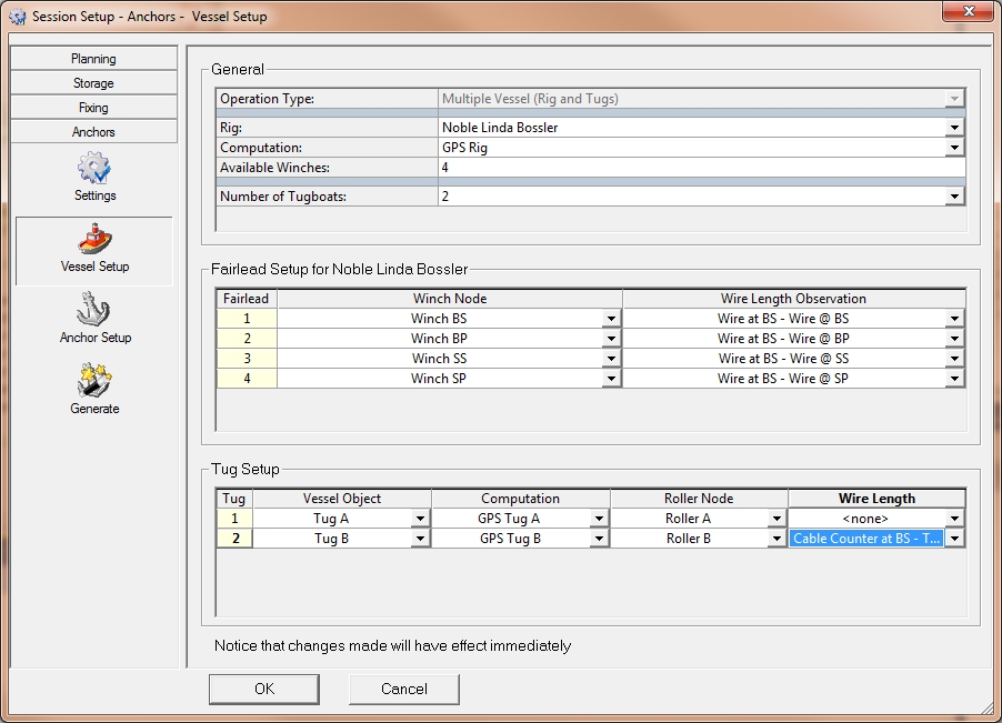
Typical Vessel Setup for a rig with two tugs
The Wire Length observations are optional and are only used when the catenary calculation is activated.
For every winch a wire length observation can be selected, this should be a Miscellaneous System observation.
Anchor Setup
When the Vessel Setup is complete, the Anchor Setup can be defined.
The window is empty when it is opened.
With the Add button an anchor can be added. Only one anchor at a time can be added.
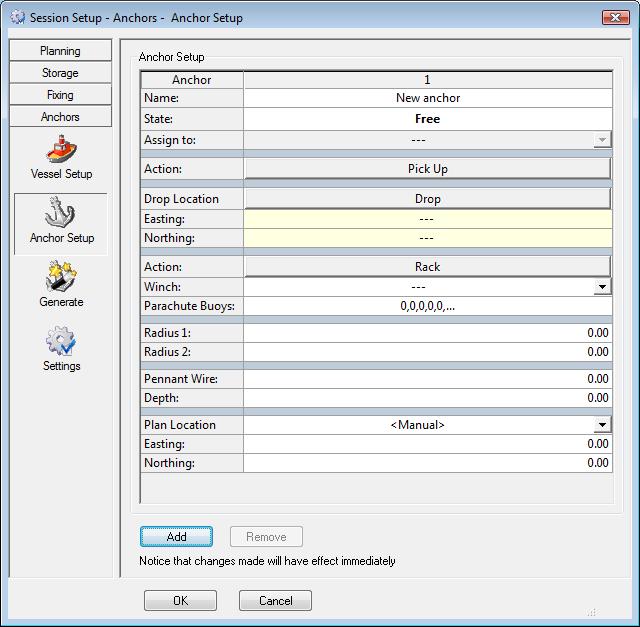
Each new anchor must be defined.
- A name can be defined but later the name will be overwritten by the name of the point selected from the line database.
- The “State” indicates what the status is of the anchor.
- Select to which winch the anchor is connected.
- 4 midline buoys or parachute buoys can be defined by the distance from the anchor to the buoy. The distances are separated by a comma and 0 means no midline buoy.
- Around each anchor 2 circles can be drawn
- Water depth and the length of the pennant wire can be defined: the result of the two figures is a third circle within which the buoy can move.
- The planned drop location can be defined manually or a point can be selected from the current line database file. When this is done the “State” of the anchor changes to “Not Assigned”,
- Now a tug can be selected in the field to the right of “Assign to”. The — means that the anchor is not assigned to a tug. When an anchor is assigned to a tug, the “State” changes to “Racked”.
- The “Action” button “Pick Up” can now be pressed when the anchor handler tug has picked up the anchor.
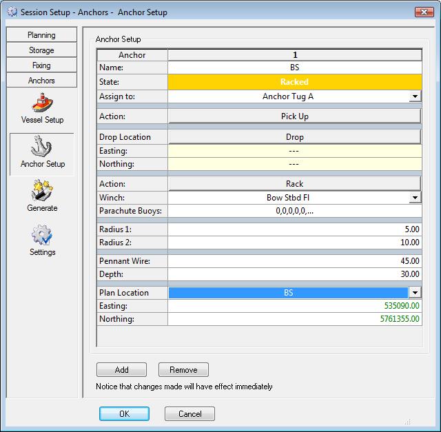
For each anchor this has to be done. And for 4 anchors this is the setup:
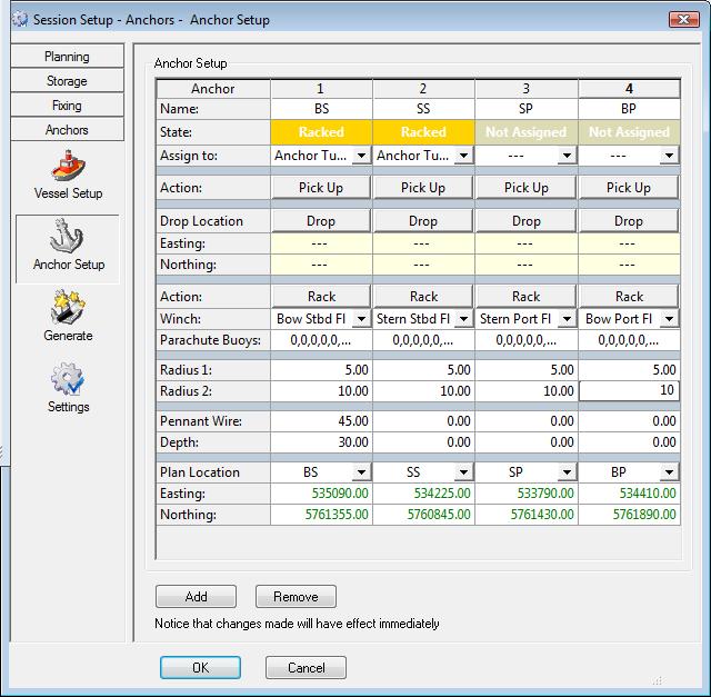
Navigation Display
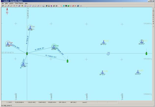
When this is done, the Navigation Display can look as follows:
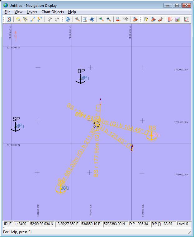
This is an example for when two anchors are racked and two anchors are assigned to a tug. When an anchor is in transit, a dynamic rubber band is drawn between each winch and anchor.
A dropped anchor has a blue solid line to the rig and a dashed line to the tug and from the tug to the rig as long as it is assigned to the tug.
An anchor in transit has a green solid line between the rig and the tug and a dashed line between the tug and the planned drop location.
When an anchor is racked and assigned to a tug, a yellow dashed line is drawn between tug and planned anchor and between rig and planned anchor. Parallel to each line range and bearing information is displayed.
To insert an anchor pattern that has been made in the Generate window, a “line database” must be imported in the Navigation Display.
- Select Line Databases from the Layers menu.
- In the window that appears select Add. Open the file to import and finish with the Apply button.
- In the Navigation Display select Anchors from the Layers menu to open the following dialog.
This dialog gives you the possibility to show anchors, planned or dropped, with or without their names and a line between the anchor and rig or tug.
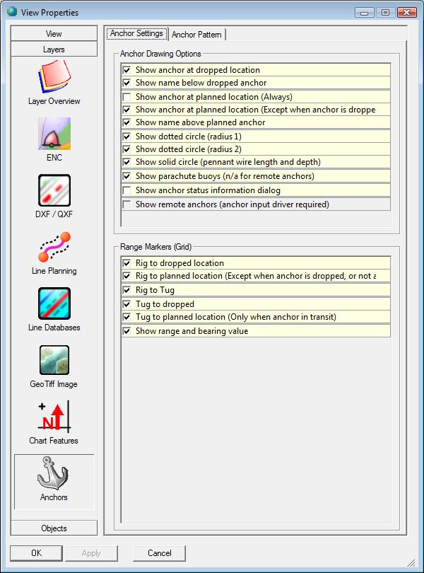
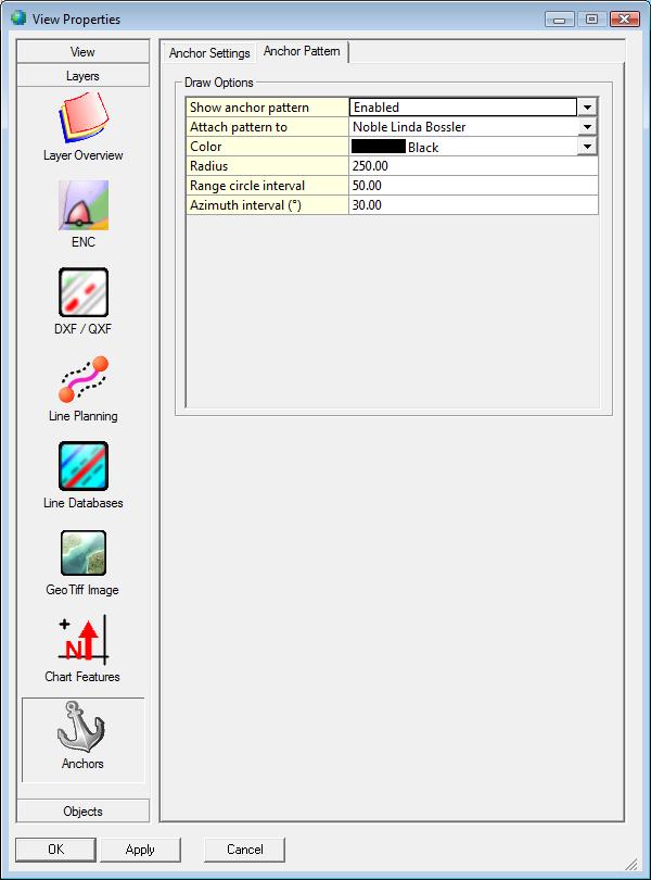
An anchor pattern is available: it is displayed after enabling this option in the tab Anchor Pattern.
From the moment an anchor is assigned to a tug the Anchor Status Information window can be activated in the Navigation Display. To view this go to View-Properties-tab Anchor Settings-check show anchor status information dialog. This window contains all the anchor information.

When the anchor handler tug has picked up the anchor, or has it onboard, press the Pick Up button in the Anchor Setup of the Session Setup. The “State” of the anchor changes to “Transit”. An anchor in transit can be dropped or racked so these two buttons are active now in the anchor setup.
Remote Anchors
Qinsy has the capability to display up-to-date anchor information that is generated on another Qinsy computer.
The two computers exchange the anchor data over a (wireless) network connection. The TCP/IP (Network) settings of both computers must be set up correctly.
A typical setup for remote anchors is when the anchor foreman will operate the “Anchor Handling” Qinsy computer while the surveyor operates the online navigation Qinsy computer.
The Anchor handling Qinsy is in this case the so-called remote system that delivers the anchor data to the so-called local Qinsy.
Another possibility to use remote anchors is when there are two barges with anchor handling tugs close to each other and on both barges all vessels and anchors must be displayed.
Online Navigation Qinsy Computer
Start the Database Setup to modify the template. Note that the template database on the local machine may be totally different from the template used on the remote machines.
To get the same information on the survey and anchor pc, define on the survey pc an output driver which sends position and heading information from the barge/rig and tug over the network to the anchor pc.
To read the anchor information from the remote pc on the survey pc, a new system must be added, Type: “Miscellaneous Systems”, Driver: “Anchor Input (Network)”.
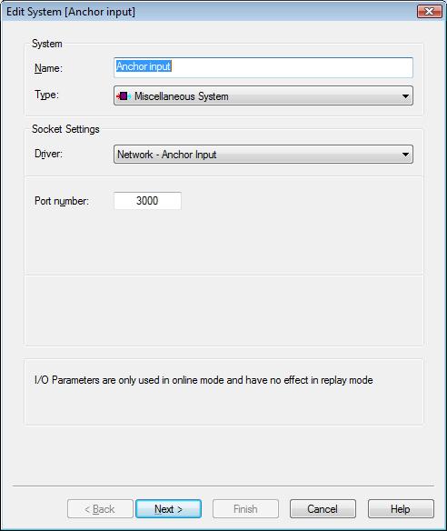
Then click twice on Next and on Finish.
The remote and local template MUST HAVE the same geodetic parameters; this is because grid positions are being transferred.
Different geodetic setups may display the anchors in the wrong position in the navigation display.
In the case of two barges, add the second barge with its anchor handling tug to the Database Setup.
The position and heading information of these two remote objects is sent to the first survey pc by Win sockets.
To send anchor information over the network to the Second Qinsy pc use an Output driver, Anchors Output (Network).
Anchor Handling Qinsy computer
The Anchor Handling Qinsy is the system where the anchors can be changed. It will send its anchor status every second to the Online Navigation Qinsy computer.
Copy the template database from the Online Navigation Qinsy computer. The position and heading drivers are Win Socket drivers which can read the data from the survey pc over the network.
An “Output System” must be added on the remote pc, with the driver named “Network - Anchor Output (UDP)”. Enter the port and IP number of the system where to send to, in this case the Online Navigation Qinsy computer.
Update rate can be set to 1.0.
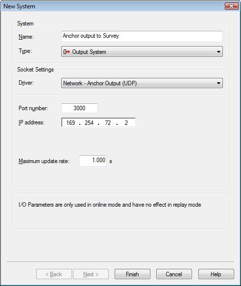
The Database Setup on the Anchor Handling Qinsy computer, in the version with two barges, looks like the online Qinsy setup but it is the opposite.
The normal position and heading drivers in the online Navigation Qinsy setup must be replaced by Win socket drivers. Change also the port numbers of the anchor input/output drivers.
Save the template and start the Controller. Online, the Output driver will be started and will send Anchor data.
Online Navigation Qinsy Computer
Go online and start a navigation display.
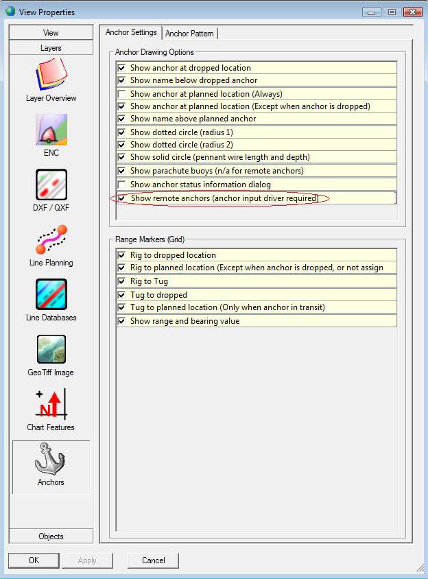
Select Properties from the View menu. Select Layers. If any anchors are available on the system (either locally defined or from remote) then the Anchors Icon will be displayed at the bottom end of the icons of the left side of the options display.
See below for a screen capture.
Press the anchors icon. Enable the option check box named ”Show remote anchors (anchor input driver required)” to show the remote anchors.
The Anchor Info dialog will also show the anchor information from either the Online Navigation Qinsy computer or the Anchor Handling Qinsy computer.

In the Anchor Status Information window the remote anchors get an R behind the names.
Tug output from the Tug Manager output driver
Use Database Setup to add an Output System to the setup, and select the Tug Manager driver and the COM port over which the data will be sent.
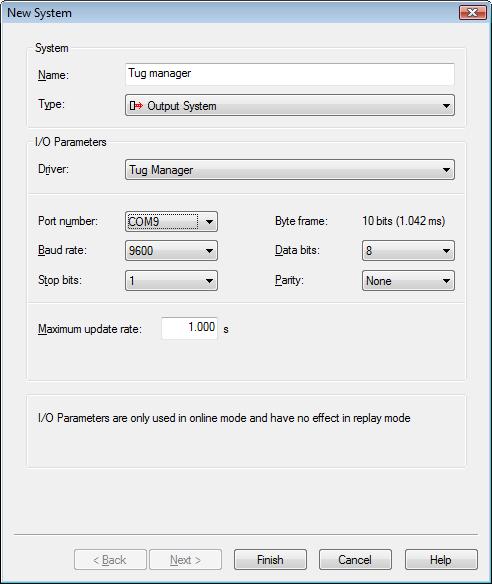
Depending upon the capability of the telemetry link, one link can be used for each tug, or one link can be used for more than one tug.
When one link is to be used for each tug, one Tug Manager needs to be defined for each tug.
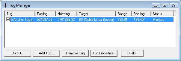
Tug Manager is a driver to output tug positions to the Tug Display. User should click “Add Tug” to add a tug and click “Tug Properties” to set the nodes for the stern roller and the antenna.
Make sure the entered properties are exactly the same as the ones entered in the Vessel Setup - Tug, otherwise no data will be transmitted.
The target is obtained from the Anchor Planning dialog in the Controller. The driver supports multiple tugs.
It is important to give each tug a unique ID so that the Tug Display on the tug can filter out the data meant for that tug. By checking/un-checking the checkboxes in front of the tugs data can be sent (or not).
Use the Tug Manager display to check that the correct data is transmitted to the tug.
The Tug Manager is developed in conjunction with the Tug Display. In operation it will make use of a two-way radio telemetry link.
The tug position (and heading data when a compass is installed) will be sent to the rig/barge.
Only when this is sent in a combined GGA / HDT message, it is advised to use the combined NMEA GGA/HDT input driver.
On the barge, the tug data is sent back to the tugs.

If there is a two-way radio telemetry link each tug will get a position / heading on an I/O port and for all the tugs one I/O port for the Tug Manager output driver.
In the Output option menu the option to compress the output tug data is available.
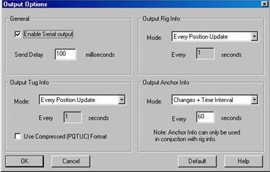
More information can be found in the Drivers and Interfacing Manual.
Tug Display
The Qinsy Tug Display is intended as a stand-alone application that receives data from Qinsy.
Install Qinsy and make on the desktop a shortcut to the TugDisplay.exe in the Qinsy folder. The Tug Display runs without a dongle.
The Tug Display is designed to run on simple Notebook type computers (Pentium with limited RAM memory) that can easily be deployed on tug vessels.
No computations take place within the display: it merely decodes and displays what is received from the Qinsy Survey computer.
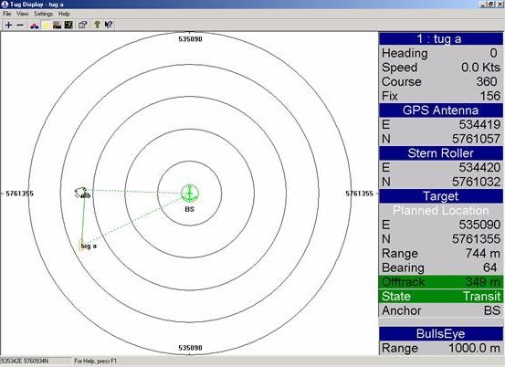
The Tug-display will display the barge/rig and all tugs.
To select the barge/rig go to Settings - Rig.
Define the rig name and select the rig shape.
In the same Settings menu the tug can be defined.
The tug ID must be the same as defined in the Tug Manager otherwise the alphanumeric info on the right hand side is from another tug.
To get the information on the correct port, follow the Serial Input setup wizard.
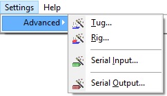
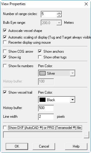
In the View Options adjust the view to your satisfaction, it is also possible to import a DXF or PRO background file.
When no data has been received by the display for more than five seconds, the alphanumeric info turns red, indicating bad data.
Info
Parachute buoys are not drawn for remote anchors, because the parachute buoys information is not part of the message that is sent over the network.
