Skip table of contents

CSD - Manual Layback (dX/dY/dZ) Relative Position

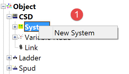
Manual Layback (dX/dY/dZ) System

If there is no pseudo-USBL system reading dX/dY/dZ values from the dredger PC/PLC but there are one or more nodes for which you want to calculate position, the Manual Layback (dX/dY/dZ) system can be used.

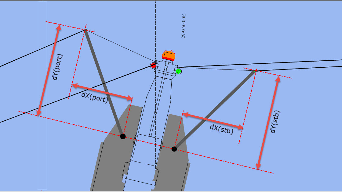
For example enter dX, dY and dZ values manually when Online if position is needed for the ends of the anchor booms.

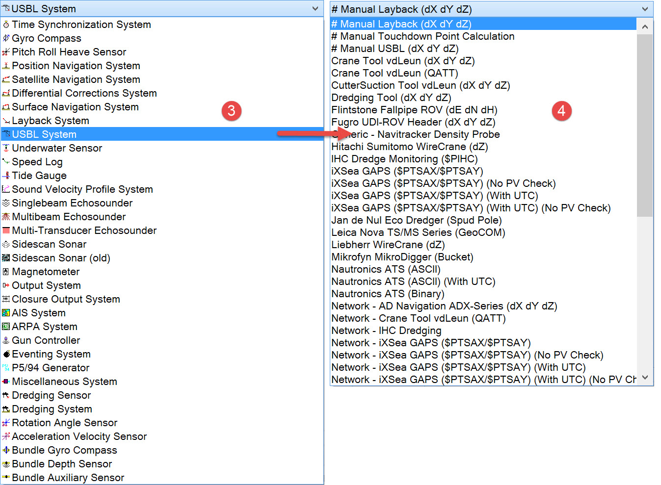
The Layback System type and driver Manual Layback allows definition of a simple slant range. Online there is a choice of observations to orient the range, i.e. object gyro, course over ground.
In the past this system has been used to connect related objects by defining a node on one object and a corresponding node on a second connected object, and leaving the manual layback value at zero.
This method of connecting objects is still valid although superseded by the Link System. 

Add a new system by selecting “Edit” from the menu bar, and then “New” and “System”, or right click on the item System in the item tree.

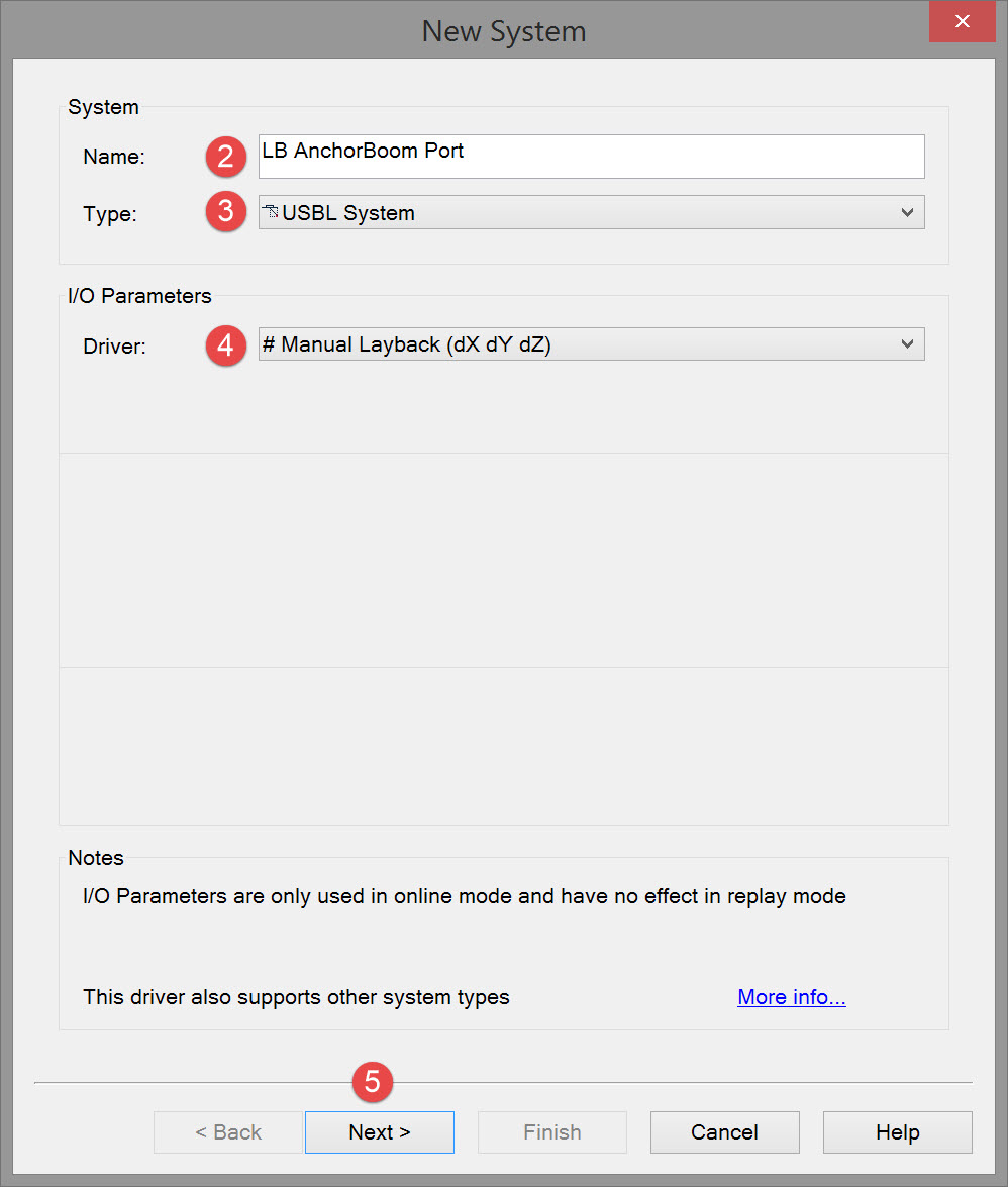
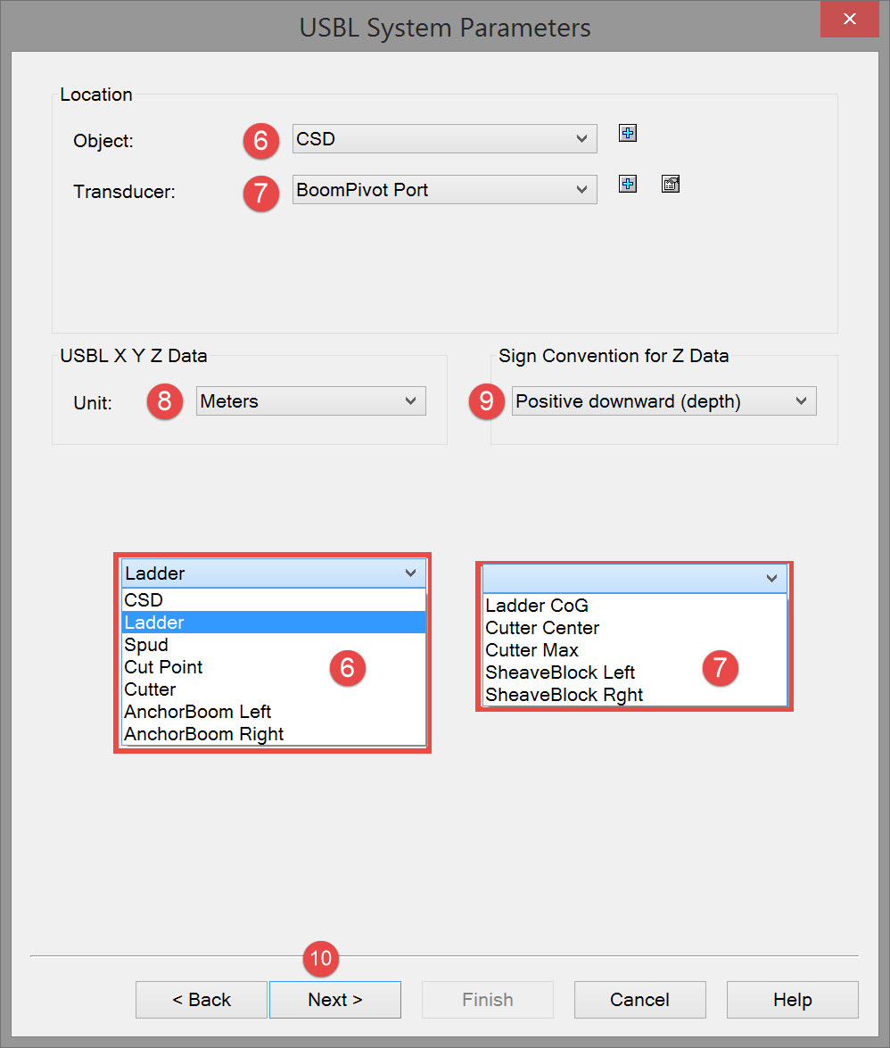
The following dialog opens. It is the first page of a wizard that steps you through the system definition process.

Enter an appropriate name that provides instant recognition in Online displays of what and where it is.

Select USBL System from the drop down list.

Select the Manual Layback (dX dY dZ) driver.

Click Next.

Select the object FROM which the dX/dY/dZ measurement are made.

Select the node FROM which the dX/dY/dZ measurement are made.

Select the measurement unit.

If the TO node is above the FROM node the dZ value is probably Positive Upward. If below the choice is usually Positive Downward.

Click Next to advance to the third page of the system wizard.

The standard deviations on this page are a measure of how well the dX, dY and dZ values can be measured or estimated.

Click Next.

Use the Add button to open the Select Nodes dialog.

Select the 'target" node for which position must be computed.

If the node you want is not yet defined (i.e. appearing in the list) use the
button to add a new Variable node.

If the node you want is not yet defined (i.e. appearing in the list) use the 
button to add a new Fixed node.

Click OK to close the Select Nodes dialog. The selected node is listed back in the USBL Targets dialog.

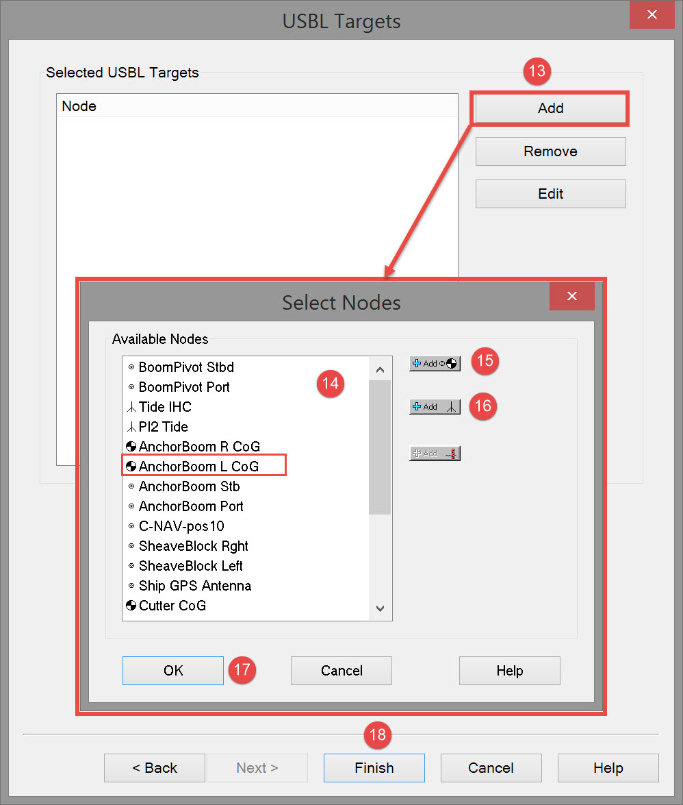
Use the Add button as many times as necessary to select more 'target' nodes.
Use the Remove button to de-select previously added nodes.
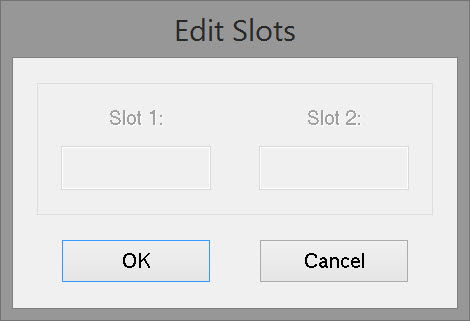
The Edit button opens the Edit Slots dialog in which slot numbers are assigned. In this case no slots are required.

Click on Finish to complete the system definition.

Return to top of page.

Return to: Cutter Suction Dredger (CSD) - System Definitions

JavaScript errors detected

Please note, these errors can depend on your browser setup.

If this problem persists, please contact our support.