
Cloned Gyro System Definition
The underlying design of QINSy does not allow, for example, using different gyros and motion reference units for different computations on the same object. Nor is it possible to use a gyro system defined on one object to orient a second object when the second object is restrained to have the same heading as the first object.
As a remedy the System Cloner driver is used to duplicate certain system types without the need to physically split their interface channel (e.g. serial port). Essentially the driver copies the observation information from the original driver and makes it available to the rest of the system as if it was a separate observation.
In the case of a cutter suction dredger, the heading of the ladder does not change with respect to the pontoon, i.e. they both have the same heading. Therefore the gyro system defined for the pontoon can be cloned so it applies to the ladder. It can also be cloned to the cutter head and the carrier spud.

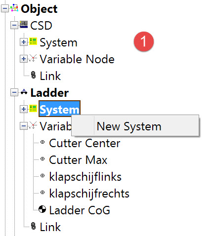
The opening dialog of the System wizard looks like this:
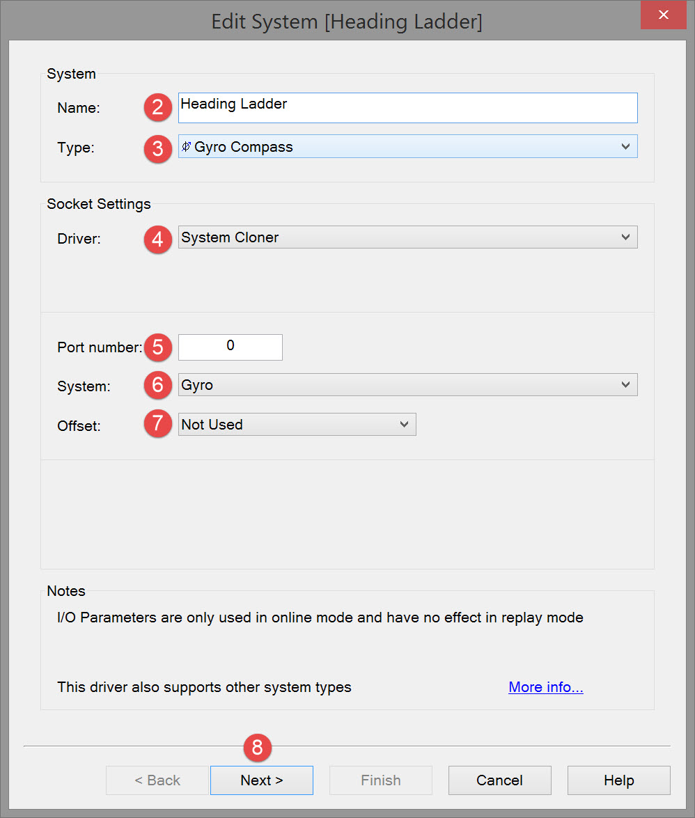


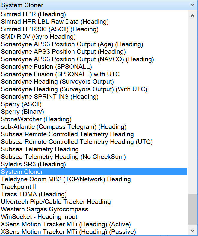


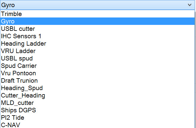
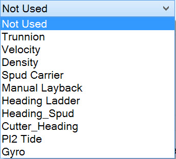
All the sensor systems defined to date in the template database are listed. In the example these are:

Select the system that will provide the offset value. This system must be of the same type.
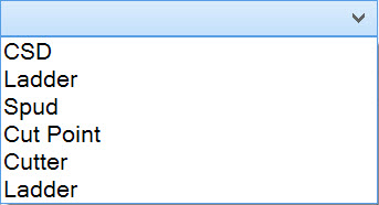
All the sensor systems defined to date in the template database are listed. In the example these are:
For a gyro, the offset system might be a gyro with manual input. Such a system allows for a constant rotation of object 2 in relation to object 1.




|
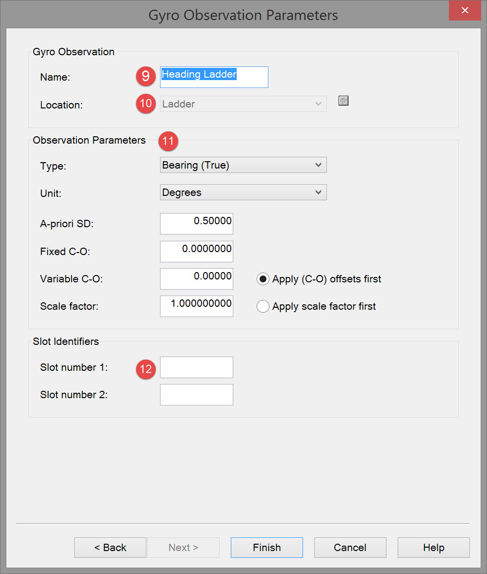
Observation Parameters |
|
|---|---|
|
Type |
Select Bearing (True), only option. |
|
Unit |
Select the type of units the gyro is outputting. This should be the same as for the primary gyro located on the pontoon. |
|
A-priori SD |
Enter the a-priori SD value of the gyro. Usually the default value is acceptable. |
|
Fixed C-O |
Enter fixed C-O correction. Fixed (C-O) corrections do not vary over time or location and must be recorded in the same measurement unit as the observation they refer to. |
|
Variable C-O |
Enter Variable C-O. The value for the Calculated minus Observed correction you enter will be added to the raw observation value.
|
|
Scale factor |
The Scale Factor or Calculated divided by Observed correction should correct the raw observation measurement unit to the standard measurement unit.
|

In this case no slot number is required as the original gyro observation for the pontoon had none. So these fields can be left blank.

Return to top of page.
Return to: Cutter Suction Dredger (CSD) - System Definitions