
Positioning System Definition
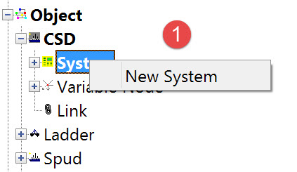

The following dialog opens. It is the first page of a wizard that steps you through the system definition process.
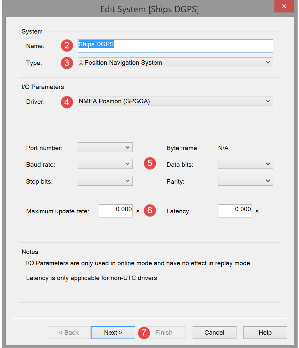


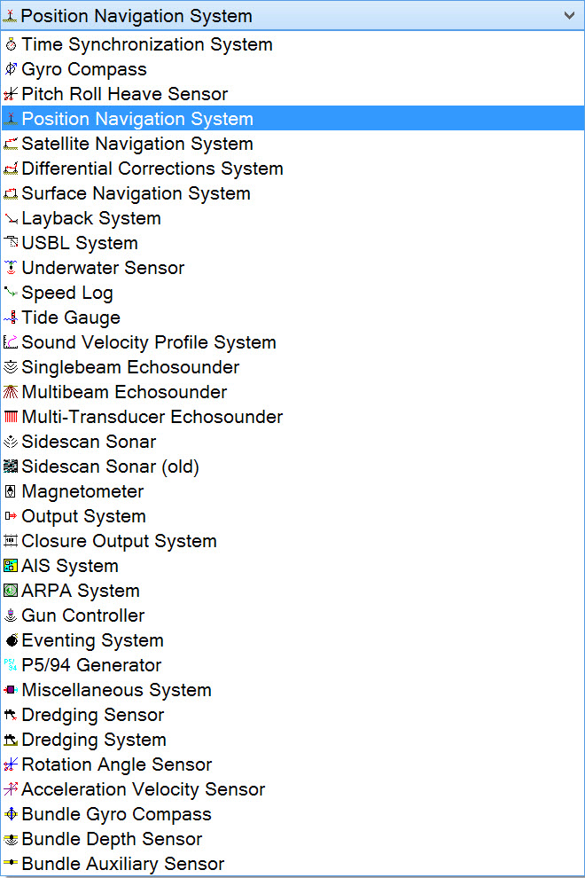

Note that the interfacing can be either serial or network so make sure to select the correct type.
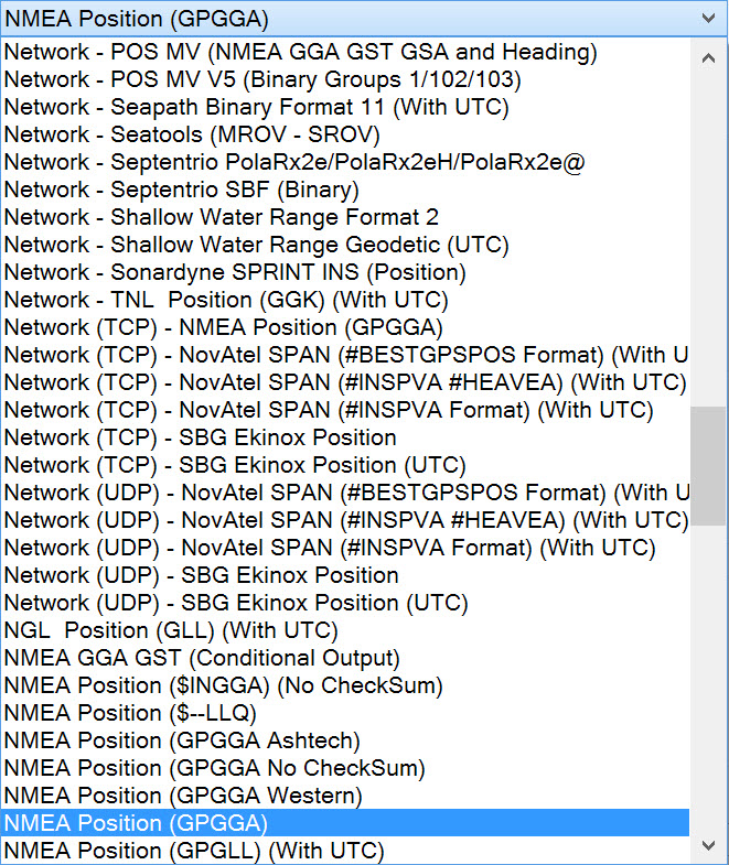

Please refer to A Note on Interfacing Parameters.

|
Updates |
|
|---|---|
|
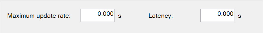
Maximum update rate |
Enter a value to determine how often data will be decoded by the interface driver. Some equipment is capable of outputting data at high output rates, but it may not be necessary to use each update. A position navigation system may for example output values tens of times per second, where five times per second is sufficient. In this case, enter a value of 0.20s. Any data not decoded by the driver is lost and cannot be recovered later. |
|
Latency |
Latency is the time between the actual measurement made in the position navigation system and the time the data message arrives at the port. The time in QINSy will thus be the arrival time corrected with the latency.
|

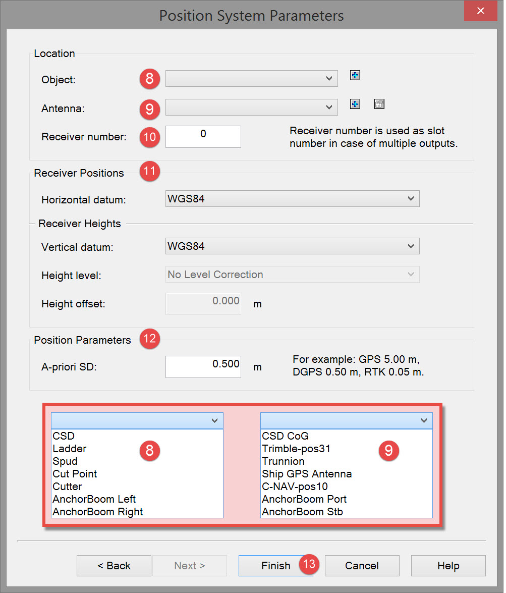

If you have followed all the steps so far in this Howto document, the drop down list will include all the objects you defined.
If you are proceeding from defining one object (the CSD vessel) the list will have only that one object.

If you have followed all the steps so far in this Howto document, the drop down list will include all the variable nodes you defined.
If you are proceeding from defining one object (the CSD vessel) directly to defining the position navigation system the list will only show the CSD reference point (CSD CoG).
The position navigation system point of measurement (typically the GNSS antenna) is usually not located at the vessel reference point so an additional variable node must be defined.
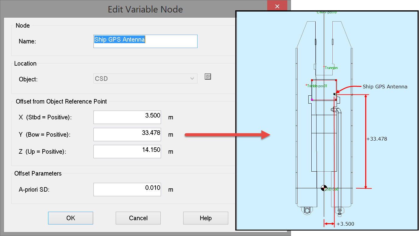
Click on the blue plus sign 
In the resulting dialog box type in a name for the new node, and enter the offsets of the antenna FROM the reference node TO the antenna node.

The signal from one antenna is split to two different GPS receivers, then in reality the same position on the vessel is used twice.
In the software this is handled by using a receiver number. Sequence starts at 0 and continues with 1, 2 etc.

Horizontal and Vertical datums
Typically the position navigation system is a GNSS receiver, usually set up to output positions based on the WGS84/ITRF/ETRS89 datum.
In some cases, the reference datum for position output is changed (especially in the case of RTK GNSS).
Always check the positioning systems reference datum and select the appropriate datum for both horizontal and vertical positioning components.
If the GPS receiver is outputting on local datum then select the local datum.
If heights are output on a Geoid, select the appropriate geoid. Then height corrections are an option.
Height corrections
Height level - Option to adjust the output heights with a correction. (See the Help at Edit - Geodetic Parameters - Mean Water Level Model for details).
Height offset - Option to enter a fixed height offset in survey units.

In setting up the computations when Online the value entered here is the default value used in calculating Total Propagated Error.
The value entered here has a great effect on the TPE result so be realistic with your entry.
Typically the QINSy default value for DGPS (0.50m) is appropriate. When working with RTK a more appropriate value might be 0.05m.
When Online/Replaying, it is possible to choose between usage of this value or an alternative value defined in the Controller - Computation Setup.

Return to top of page.
Return to Cutter Suction Dredger (CSD) - System Definitions
Return to: Setup and Interfacing of Qinsy.