
How QINSy supports dredging operations
On this page:
This document outlines how QINSy Survey supports dredging operations. Four main tasks for the support of dredging are distinguished:
-
3D Positioning of barge, suction arms, cranes, grabs etc.
This is not considered a dredging specific task so is not discussed in any detail. Throughout the Howto we shall assume a valid 3D position of all the necessary nodes and objects.
-
Presentation/Visualization
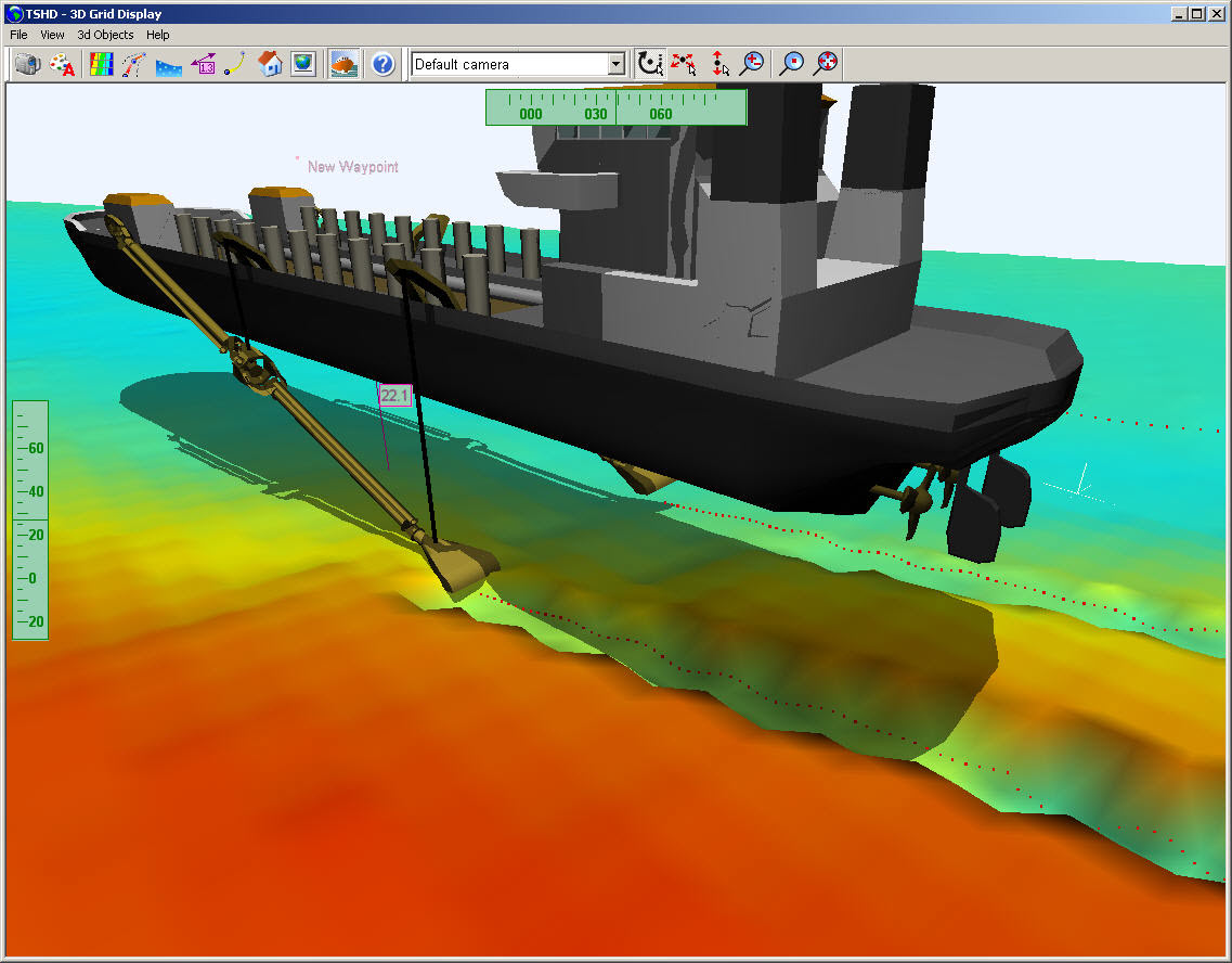
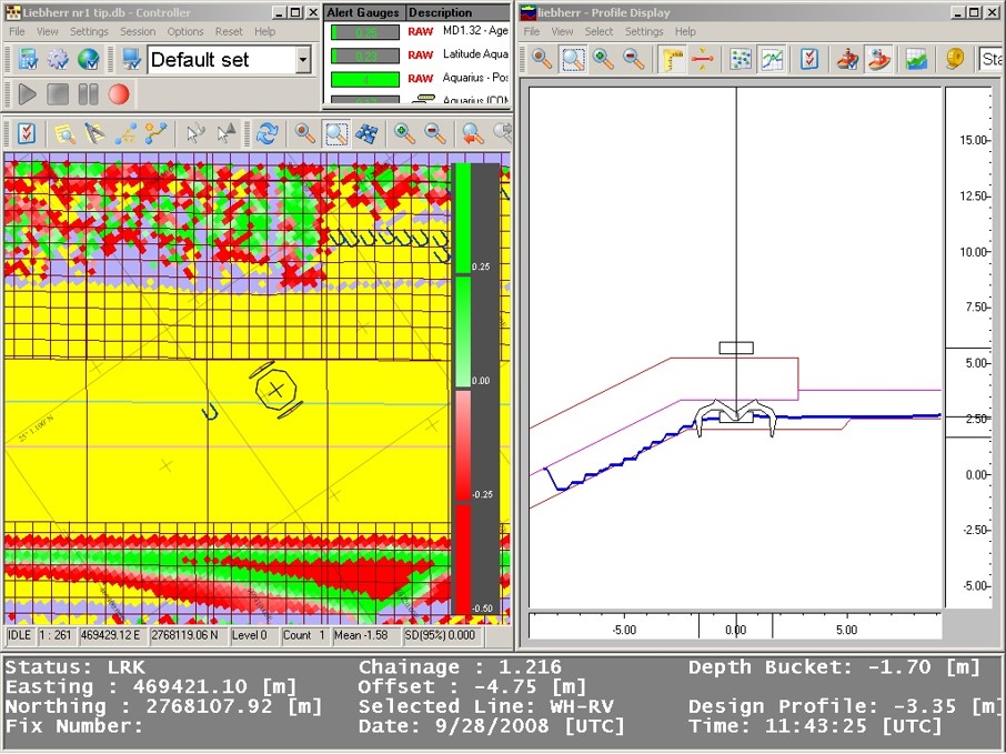
The Profile display, 3D sounding grid display and the Navigation display are very useful for dredging operations. Refer to the the Knowledge Base and online help for more information on these displays.
-
Volume Tracking
QINSy keeps track of the theoretical trip volume of a grab or a suction type dredger.
-
Sounding Grid updating
By modifying an existing sounding grid (with pre-survey data) QINSy will closely simulate the excavation or dumping by the dredger. The exact geometry of the modification is based on sensor input, position of dredge head, operational settings and theoretical dredge head model.
Supported Dredger Types
|
|
Return to top of page.
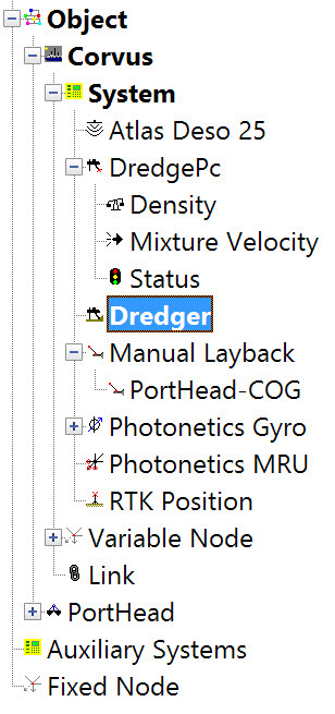
QINSy System Setup
Definition of Geodetics, Objects, Systems, Nodes and Observations
|
|
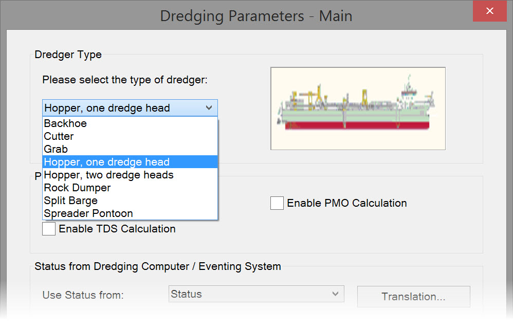
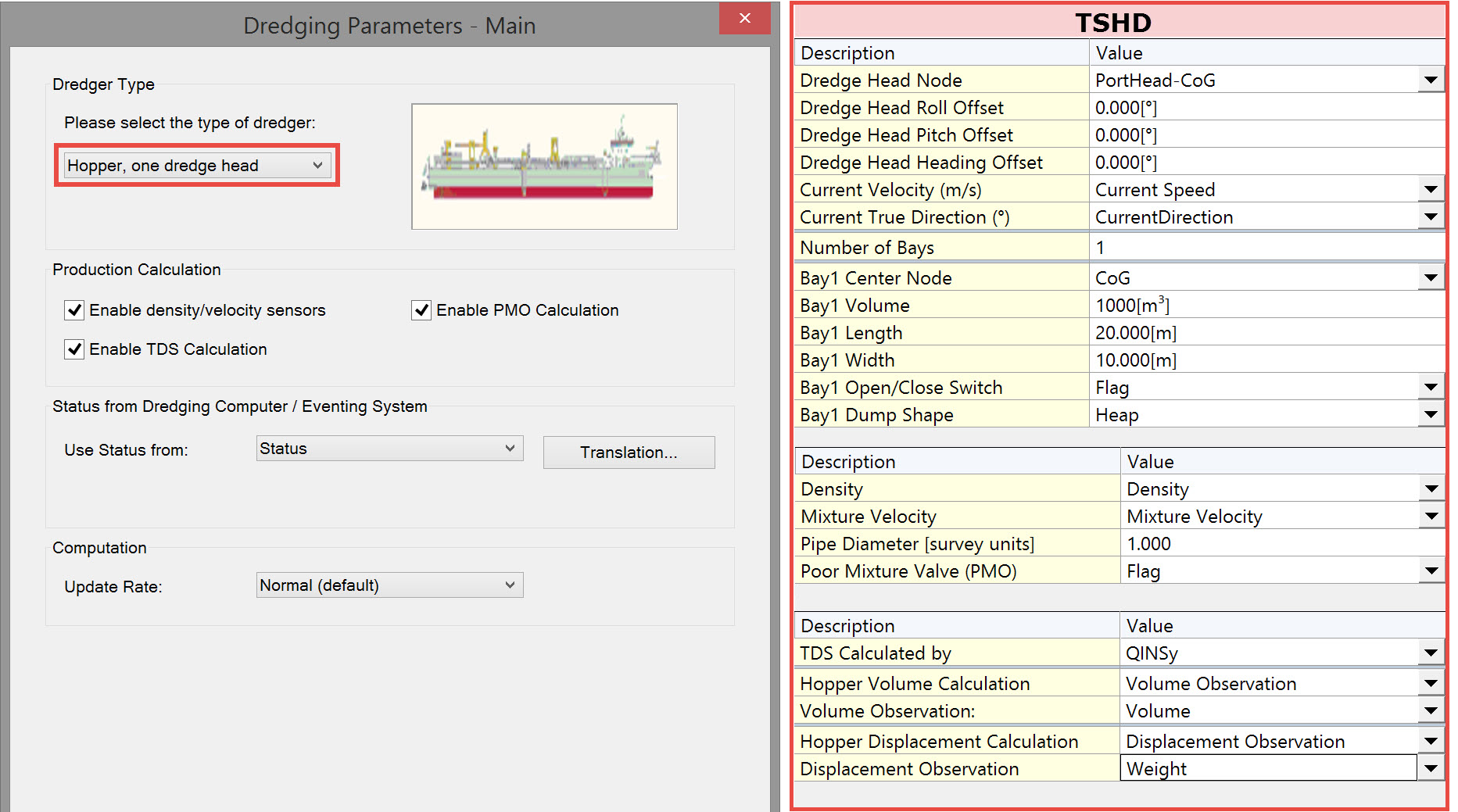
Dredging System (Dredge Type)
Selection of dredger type and definition of parameters.
|
Return to top of page.
Visualization - Object Definition
Definition of plan, starboard and aft shapes for the particular dredger. These are 2D shapes.
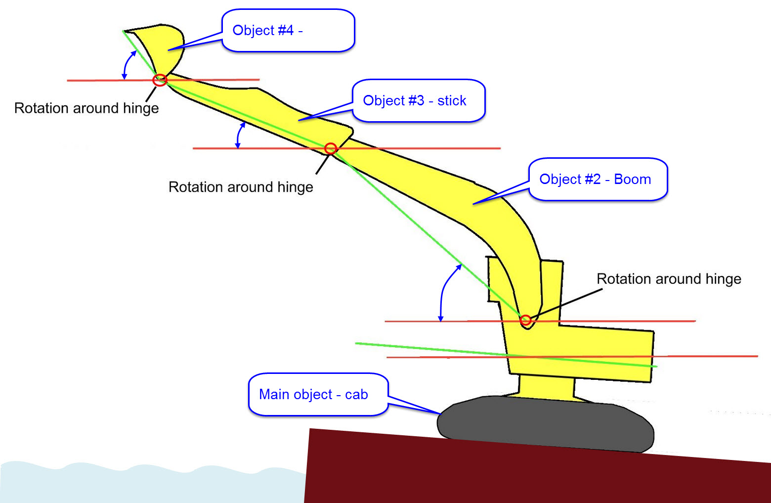
Moving parts of the dredger are defined separately. For example a backhoe comprises a cab, a boom, a stick and a bucket.
Individual objects are linked in order that they can be visualized during dredging operations
Object Linking
The object linking functionality in QINSy is designed to:
|
|
Dredge Head Type
QINSy currently supports several types of dredging tools. Depending on which type of dredging, one should select an appropriate dredge head. For example:
Grab
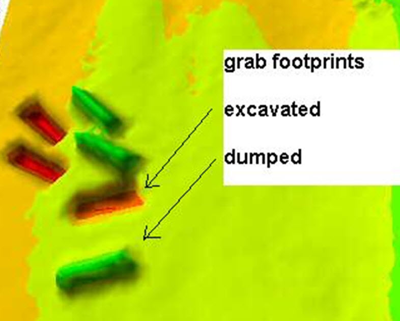
This type is selected for grab dredging. Working with a grab can be simulated as an event-driven process in which a grab can have 2 different states, open and closed. If a grab closes it will excavate a certain amount of volume, and if it opens the same amount will be dumped. A model of the footprint that is left behind when the grab closes is used to update the sounding grid.
The Event-driven Grab dredging process responds to triggers caused by observation changes of external sensors.
Suction Input
This type can be used to support dredging operation with cutters and hoppers and even rock dumpers. A sounding grid can be continuously updated depending on either the production or on the absolute height of the dredge head. A trip volume can be calculated based on production observation. The trip volume can be passed to a Suction Output system in order to be dumped using the model defined in the Output system. Once a trigger is received that indicates the pump has started, the sounding grid is updated.
Suction Output
This type can be used solely in combination with a suction Input type. A suction Input calculates a trip volume, this volume is passed to the connected output system and is dumped instantly when the bay doors are opened. The trip volume is distributed over the seafloor in accordance with the head model as defined in the Suction Output system.
Return to top of page.
Dredge Head Model
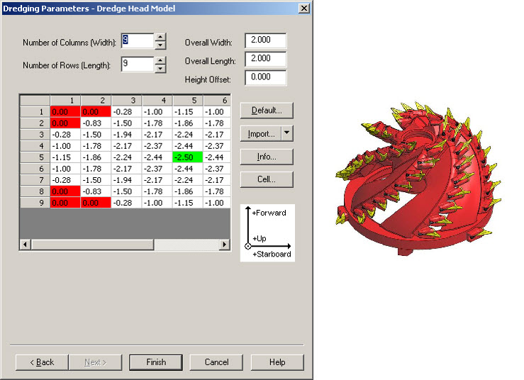
Dredging tools come in many different shapes and sizes, leaving a unique footprint behind on the seafloor after an excavation has been made. Within QINSy a model of this footprint can be defined in Database Setup as part of the Object definition wizard.
The model is represented by a variable sized M x N matrix with height values and a certain length and width.
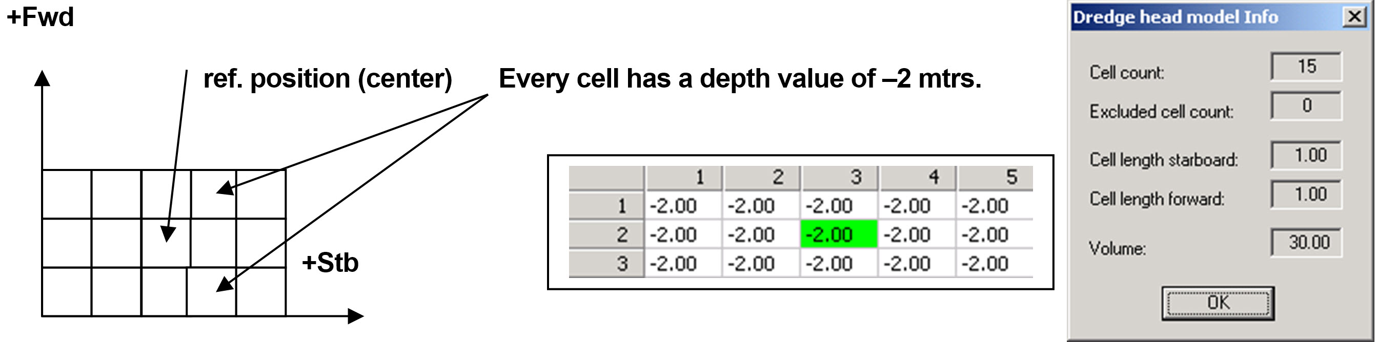
The QINSy core process “Multibeamer” generates M x N soundings that update the sounding grid. When a cell of the sounding grid is “hit” by the sounding it will be modified.
The number of rows and columns (M, N), cell height and width are user-defined; M and N must be odd.
Every cell in the matrix represents a height from the reference point of the tool.
Cells can be excluded from the model when a footprint is not a square but, for example, oval shaped. These are colored red as in the picture below.
|
|
When determining the number of rows and columns of the matrix, one should take into consideration the required accuracy, sounding grid cell size and available PC power.
Every matrix cell will represent a sounding so the more cells, the more CPU load it will take to process the soundings and the higher the accuracy.
However the most important factor is the cell size of the sounding grid you wish to update. If the size is 0.5 by 0.5 units then choose a head models’ cell size of at least 2 times smaller.
This will guarantee that every grid cell is hit by the model’s sounding with every possible barge heading.
Example: a grab leaves a simple square shaped footprint behind on the seafloor of 3x5x2 meters (purely hypothetical of course).
It could be defined as:
Cell size = 1X1 meter: (width = 5 m, length = 3 m)
Return to top of page.
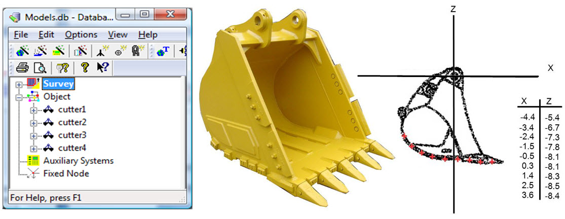
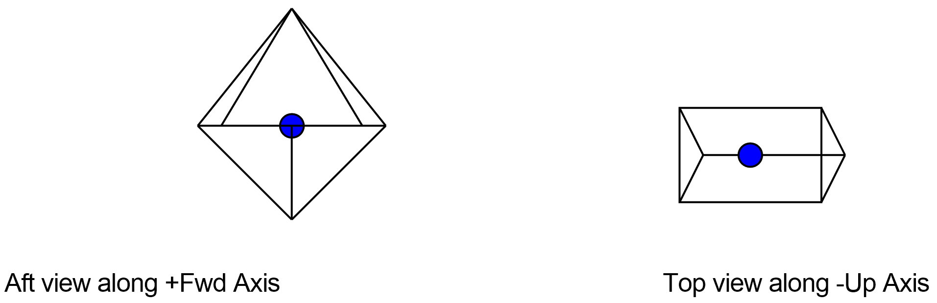
Location of Model Reference Point
|
User must define a node on an object that provides the position of the dredge head model reference position. This position is connected to the center cell of the head model matrix at height 0,0. For an example see drawing opposite; the blue point indicates the reference position of the model. |
|
Return to top of page.
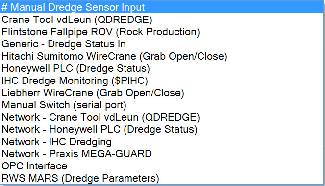
Dredge Automation Systems
Definition of communication between dredger computer and QINSy.
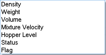
Selection of observations to decode: density, velocity weight, volume, hopper level, status and/or flag.
|
|
Return to top of page.
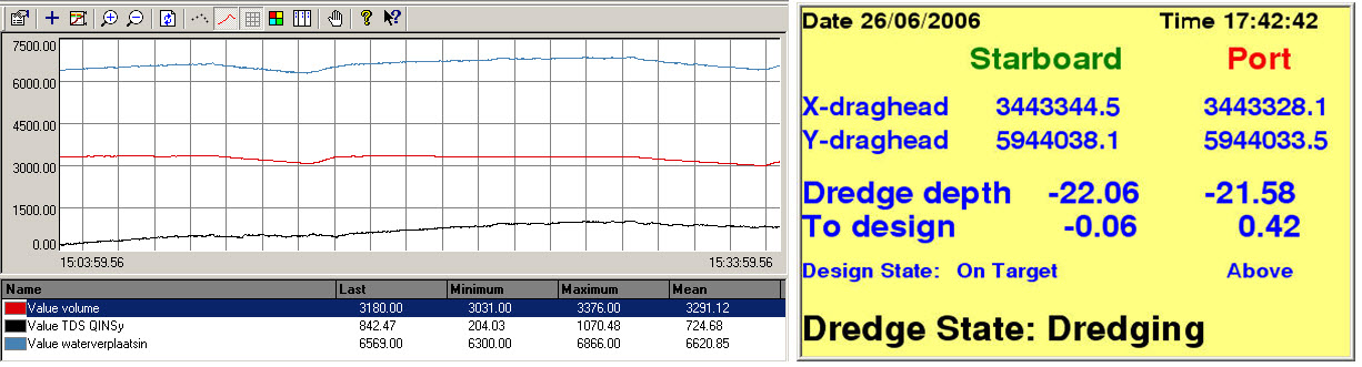
Real-time Dredging Operations
Information Shown
Positioning and orientation of dredger, dredge heads, multicats; dredge parameters.
|
|
Visualization
Visualization of the dredger and the dredge process using various 2D and 3D displays.
3D models should be Direct X files (*.x).
|
|
ColorBanding.jpg?cb=9b82a432873cc26ecee75bc7bc7a73b2)
|
Update Triggering mode
The QINSy dredging process depends on triggers caused by external user-selected sensors. It will continuously scan the observations from a sensor. A trigger is generated whenever the observed data either falls or rises along a user defined threshold value. The sensor, rising or falling and the threshold value can be selected in Database Setup, see below for an example of a trigger.

This option sets the trigger mode.
Options are:
Grab open / close (Dredge Head Type Grab only)
Two triggers must be defined, one to report the grab has opened, the second trigger is used to report closing of the grab. The close trigger will be used to store the grab position and attitude AND update the sounding grid.
Grab open / close /delayed update (Dredge Head Type Grab only)
Beside the two triggers mentioned above, a third trigger is defined that will update the sounding grid. The close trigger will now only be used to store the grab position and attitude. This option can be used when the volume of the material in the grab is measured not at the time of closing but only some time after. Example: Grab content volume that is determined from the wire tension -> weight of the grab, the tension can only be measured when the grab is lifted from the seafloor.
Continuous (Suction Input and Output only)
Suction dredging is a continuous process, once the pump has started, the sounding grid is continuously updated once the dredge head reaches the seafloor and material is pumped up.
Two triggers must be defined for a Suction Input System, one trigger to start the pump and the second trigger to stop the pump. A start trigger must have been received in order to update the sounding grid and start cumulative “trip volume” calculation.
Two triggers must be defined for a Suction Output System, one trigger to open the bay doors and another to close the doors. As soon as the bay doors are opened than the sounding grid is updated using the head model of the output system and the trip volume collected by the connected output system.
Return to top of page.
Sounding Grid Update Method
-
During dredging using the dredge head definition
-
During dumping using the the dump bay definition
This method determines how the sounding grid is updated. This can be done either in an absolute way or relative way.
The absolute method uses the absolute 3D position of the grab in combination with the footprint model to determine whether it has hit the sounding grid or not. This mode requires an accurate depth measurement and real time tide observation. If the Grab is a few meters above the sea floor and it closes, no excavation is performed.
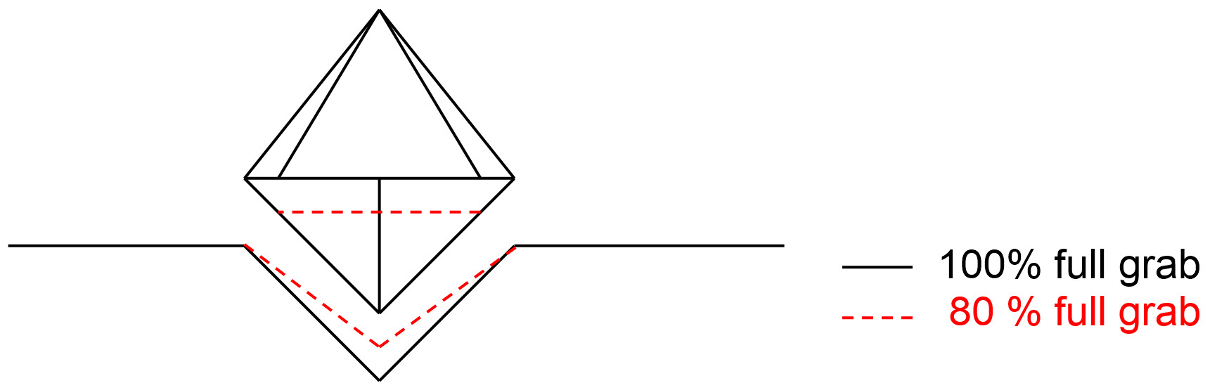
The relative methods rely on an observation of volume or fill ratio of the grab. This observation must provide how much volume of material is enclosed in the grab after it has closed. The absolute depth of the grab is ignored, only the 2D position of the grab and its attitude is used to update the sounding grid. The sounding grid cells located at the 2D position of the grab at closing time, are updated using the dredge head model and the observed volume/filling ratio. The heights within the model are applied to the seafloor; the height values are applied as entered when the grab is filled 100%. If the grab is filled less than 100% then heights are compensated for this. It is Important to remember that the horizontal edge of the footprint always has the same size as defined in the model but that the vertical depth is compensated for by the filling grade of the grab. The figure below illustrates this behaviour.
Three different relative modes can be selected. Basically they do the same except for the input observations that are used.
-
Relative - with observed volume
An external source, a sensor or input manually by the user, provides the volume in cubic survey – units of the excavated material in the grab. In Database Setup, user must select an external observation.
-
Relative - with observed fill (0-100%)
An external source, a sensor or input manually by the user, provides the filling percentage of the grab. In Database Setup, user must select an external observation.
-
Relative - assume full load
No external sensor used, instead QINSy assumes the grab always holds a full load of excavated material after grab has closed.
Return to top of page.
Update Volume Calculation
This option is used to determine how the dredged volume should be calculated. Two options are available:
-
From grid changes (only absolute update method)
The excavated volume will be derived from the changes of the sounding grid.
-
From observed volume / production (only relative update methods)
The volume calculation is based on external sensor data that will deliver an observed volume (grab) or production m3/hour (suction).
Volume calculation is used:
-
In relative update methods to calculate the size of the sounding grid change.
-
In relative and absolute update methods to keep track of the current or trip volume that is used for dumping of the material (suction out or grab opening).
Volume Observation
Here one should select the observation that delivers the observed excavated volume (grab) or production (suction). Inputs are expected to be in cubic survey-units and cubic survey / units per hour respectively. If update method is “Relative - assume full load” or update method is absolute and the volume calculation is set to “From grid changes” then no volume / production observation is required. In all other cases one should assign an observation.
Return to top of page.
Limitations
Because of ongoing developments, some restrictions apply:
-
Currently sounding grid can only be updated when recording is active, therefore whenever dredging operations are in progress, recording must be active.
-
Calculation of excavated volume based on grid changes is not yet supported.
-
Because of the point above, the dredging process does not yet keep track of the volume currently in the grab when using the absolute 3D update method. Therefore it will assume the grab is full whenever it is opened and update the grid assuming a full grab load is dumped.
-
Suction Input system is not really continuous but updates with 5 Hz. With high speeds this may become notable, the dredged track may no longer be a continuous line but looks dashed. Because of this, it is advised not use the relative update modes but always absolute for suction input.
-
No means are yet available to display either the internal states of the dredging process or the current trip volume. Either a new dredging display will be added to QINSy or the data is made available in the alphanumeric display.
Reporting
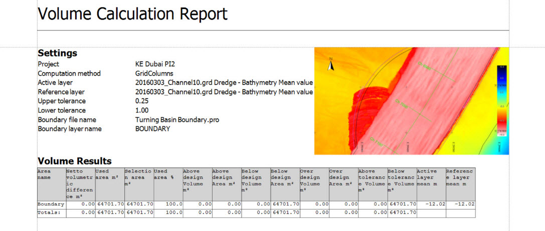
Volume calculations and trip report generated using the Processing Manager.
|
|
Return to top of page.
Other
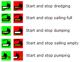
Eventing
Sometimes it is required/useful to maintain a log of dredging events:
The log contains a list of
'Events' are assigned to 'Classes of Events', e.g.:
When Online, icons can be used for display in the Eventing Driver window |
On event triggering a marker is placed and the location stored in database. |
Anchor Handling
Exchange of positioning and anchor information between dredger and anchor handling tug via telemetry link.
|
Anchor planning, pickup and drop positions directed on board dredger. Real time display on dredger of dredger, tug(s) and all anchor drop and pickup locations. Simple display on tug easily operated by tug helmsman. Requires defining a Tug Manager System in Database Setup. |
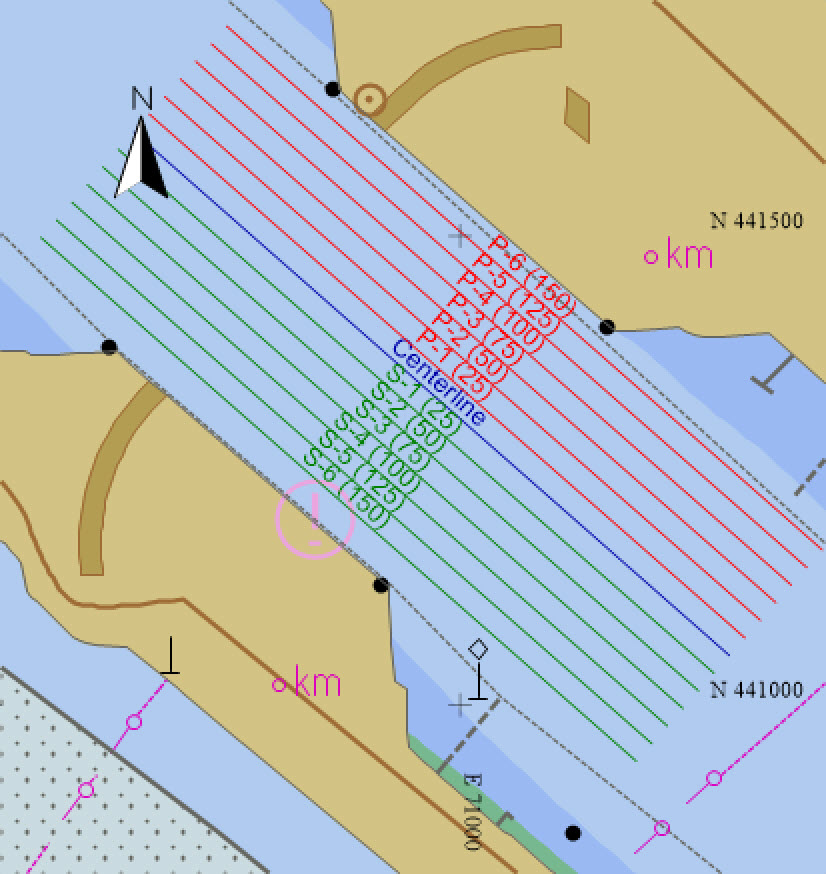
Survey Lines
The Processing Manager (PM) is used to create survey lines, routes (polylines) and points for use in planning, conducting and processing a survey. These entities can also be imported from various formats. Once created they can be exported to various formats.
|
|
Return to: top of page
Return to: How-to Dredging