
Tug Manager System Definition
When tracking of the anchor handling tugs and anchor locations is necessary, a Tug Manager system must be defined along with any tug objects.
Configuring vessels and tugs, setting up and managing anchors, generating planned anchor drop locations, and defining data storage options are all done in the online Controller under the Settings menu.

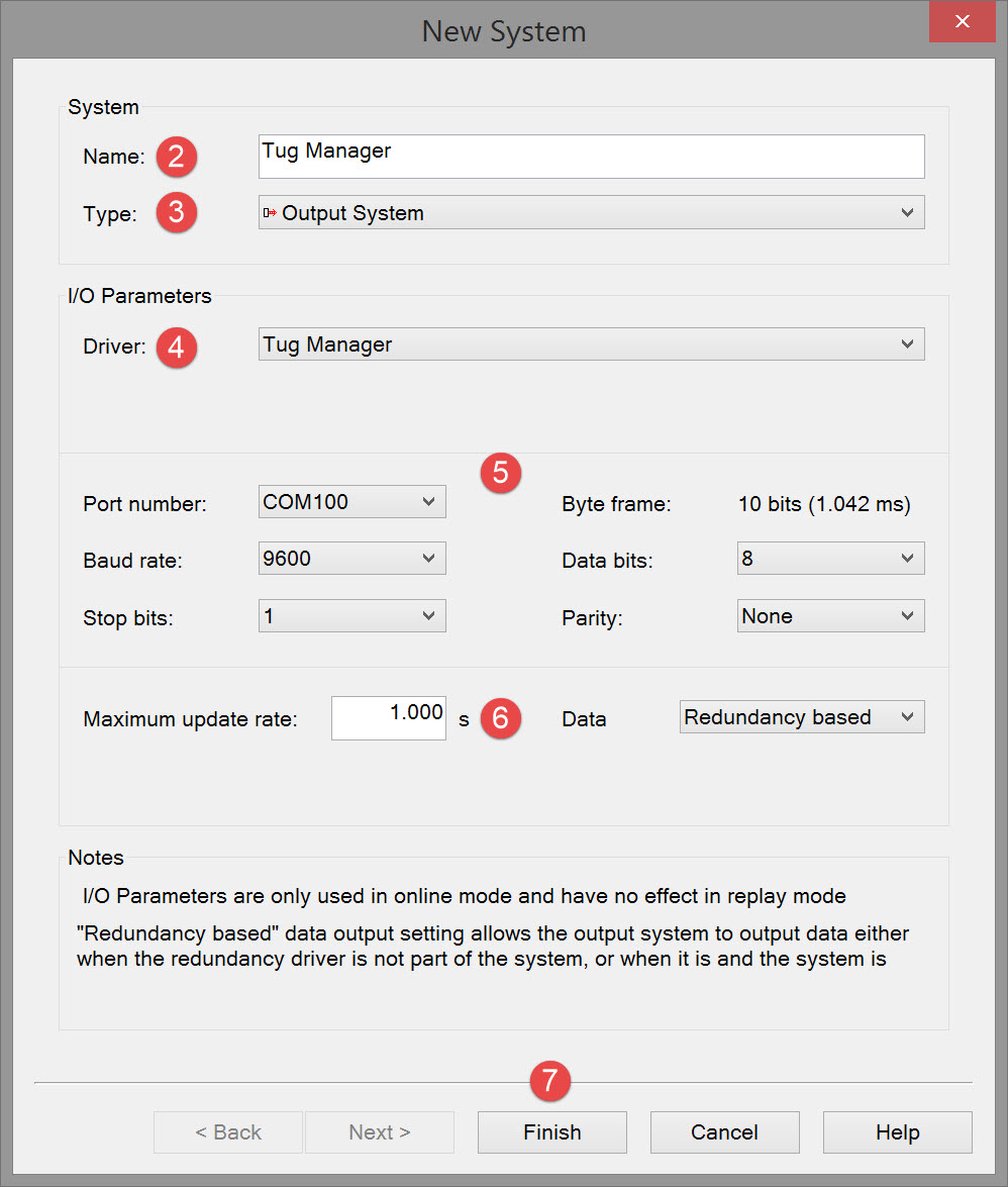
The following dialog opens. It is the first page of a wizard that steps you through the system definition process.


Please refer to A Note on Interfacing Parameters.

|
Maximum update rate |
Enter a value to determine how often data will be decoded by the interface driver. Some equipment is capable of outputting data at high output rates, but it may not be necessary to use each update. A sensor system may for example output values hundreds of times per second, where five times per second is sufficient. In this case, enter a value of 0.20s. Any data not decoded by the driver is lost and cannot be recovered later. |
|
Data
|
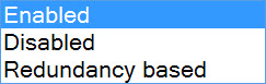
Some output drivers can make use of the Redundancy functionality (refer to Redundancy Monitor system in the Drivers & Interfacing Manual). If so this option is shown on the first page of the setup wizard. The option can be Enabled/Disabled or set to Redundancy. This setting can also still be changed online.
The purpose of the Redundancy Monitor System driver is to perform an election process which decides which QINSy system is the primary system for data output.
|

Return to top of page.
Return to: Cutter Suction Dredger (CSD) - System Definitions