
On this page:
Background Information
Click to expand...
Sounding Grid Use
A Sounding Grid is used to:
-
Simultaneously store and visualize data of different kinds, including data attributes such as 95% confidence level, min/max values, etc..
-
Compute and display surface differences, e.g. real-time dredged depth versus design depth.
-
Calculate volumes, show statistics, create contours and spot soundings for ENC's, DXF’s and PRO’s.
The grid is generated on-the-fly and has no boundary. It comprises two types of layers:
-
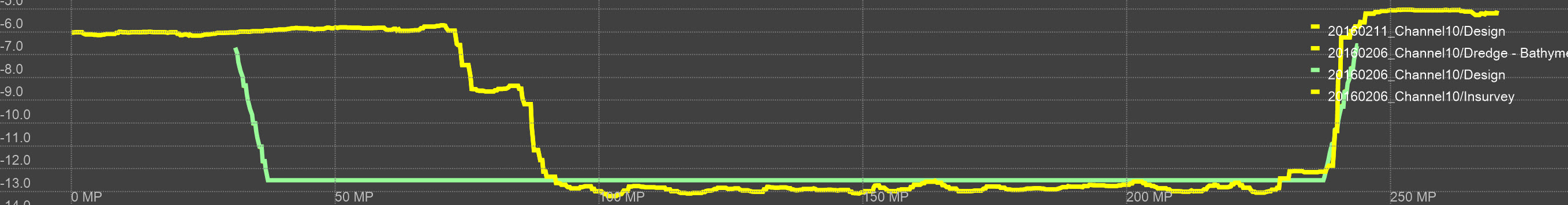
User defined layers employed to store and visualize data of different kinds, e.g. design layer, in-survey layer, mixture density, mixture velocity, etc. as indicated in the image below.
-
Regular multi-level grids. Based on the user defined minimum cell size, five additional grids are automatically generated on-the-fly. So for example, if the minimum cell size is chosen to be 1m x 1m, the following grid levels are generated: 2x2, 4x4, 8x8, 16x16 and 64x64 as an overview level. This mechanism is used when scaling the navigation display, in generating contours and in data export.
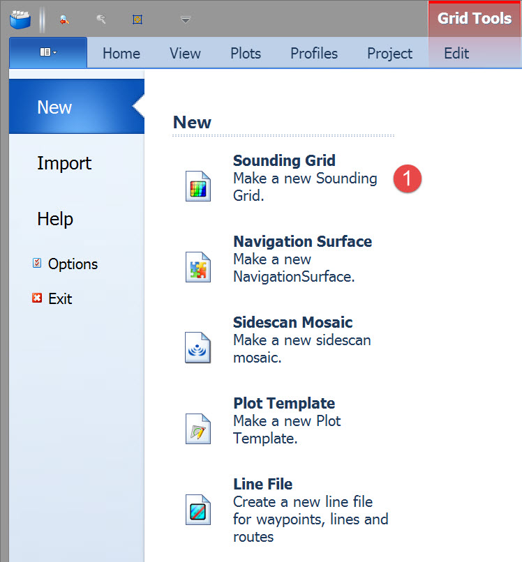
Creating a New Sounding Grid - Program Functionality
The new application was included in the Autumn 2015 release of QINSy and is used by default when creating a sounding grid from the Session Setup Storage option in the Controller.
The program's functions are:
-
Create a new sounding grid file
-
Change the grid settings of a new sounding grid file
-
Add layers to a new sounding grid file
-
Change layer settings of new layers
-
Add layers to an existing sounding grid file
Online the following dredging related data can be stored to the sounding grid:
-
Bathymetry
-
Dredge Head Height
-
Current Production
-
Mixture Density
-
Mixture Velocity
The former application is still available and is used by default when creating a new grid in the Processing Manager, and when using the stand-alone program, i.e. \Program Files (x86)\QPS\QINSy 8.1\SoundingGridUtility.exe.
Making a new Sounding Grid
There are two primary places for creating a new sounding grid:
-
Controller - Settings - Session Setup - Storage - Sounding Grid: This is the best option for dredging. It uses the newer Creating a New Sounding Grid program. At startup a number of predefined layers are available for activation.
-
Processing Manager - File - New - Sounding Grid: This option uses the previous sounding grid program. At startup only one layer is predefined. You have to add any others you want.
Sounding Grid versus Dynamic Surface (acquisition mode)
Each type can be created both in the Controller and in the Processing Manager.
Sounding Grid: During data acquisition if you add new soundings to grid cells that have previously been filled, the new data is MERGED with the existing and new attributes are computed, i.e. mean value, standard deviation, count, minimum and maximum values. See note below.
Dynamic Surface: During data acquisition if you add new soundings to grid cells that have previously been filled, the new data OVERWRITES the existing and new attributes are computed for the new data, i.e. mean value, standard deviation, count, minimum and maximum values. In dredging applications a dynamic surface has limited value as it only has one layer, i.e. you cannot add a design layer.
Sounding Grid - Overwrite Mode
This parameter is only shown when the Date attribute has been enabled during grid creation for one or more of the layers.
By default new depth data is automatically merged with existing data.
In dredging operations overwriting of existing data is often what is needed to monitor progress.
-
Age - Newer data will overwrite older data if the age of the older data is greater than the Age time entered.
-
Used when using a Multibeam on a cutter dredger. When swinging in a cut the data is averaged if the data is not older than the threshold age set.
-
This can be useful if you want to redo a survey line and only want to overwrite the sounding grid data of the previous attempt.
-
-
Time (older than) - Newer data will overwrite older data if the time tag of the older data is before the time and date entered.
Controller - Settings - Session Setup - Storage - Sounding Grid

Click on Sounding Grid.
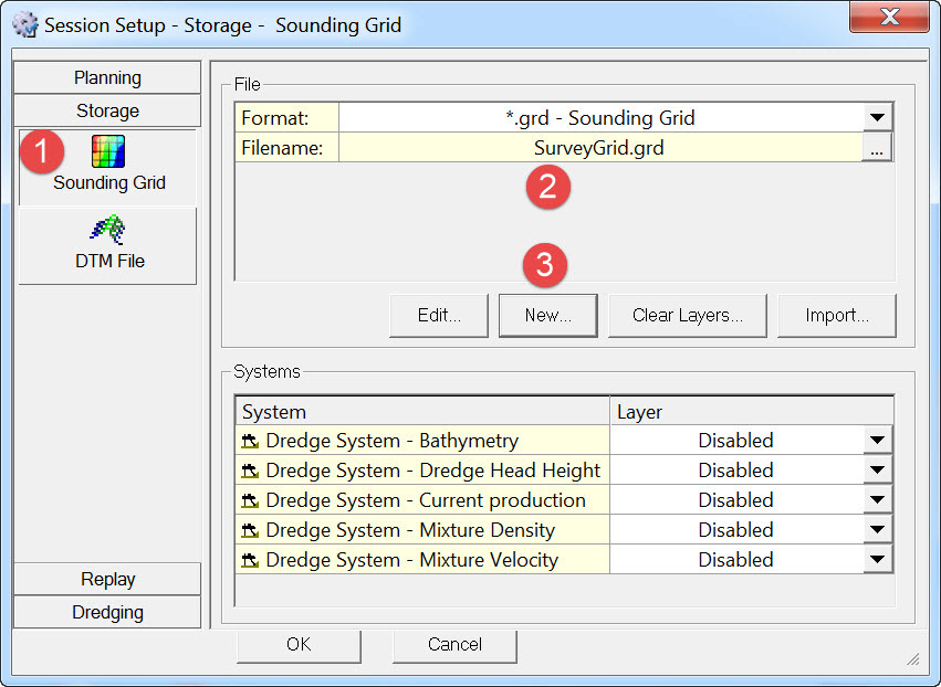


This can be done in both Online or in Replay mode. This opens a dialog with the following interface elements:
Unknown Attachment
|
Number |
Element |
Description |
|---|---|---|
|
1 |
Grid Settings |
All settings that can be modified for the sounding grid. |
|
2 |
Layer Collection |
All layers that will be added to the sounding grid upon saving. The list here reflects the selections made in element 4. |
|
3 |
Layer Properties |
The properties for each layer that is highlighted in the Layer collection. |
|
4 |
Layer Tree view |
All layers that can be added to the sounding grid.
Enable or disable attributes per layer or change the layer type to create the desired sounding grid configuration. |
|
5 |
Add layer button |
Add a new layer to the layer setup in the category selected in the Tree list.
|
|
6 |
Switch to Advanced
|
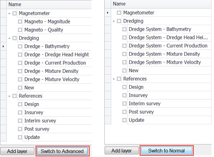
Normal mode: By default the program provides a limited list of suggested layers based on the different types of systems detected in the template or replayed database.
Advanced: The program gives an extended list of suggested layers. All systems are detected in the template or replayed database.
This option is only available when creating a New sounding grid. It does not appear when the Edit button has been used.
|
|
|
Help |
Launch this page's offline available help. |
|
|
OK |
Save a grid with the grid settings and layers, close the program afterwards and return to the Controller - Session Setup - Storage - Sounding Grid page. |
|
|
Cancel |
Exit the application and return to Controller - Session Setup - Storage - Sounding Grid page without saving anything. |
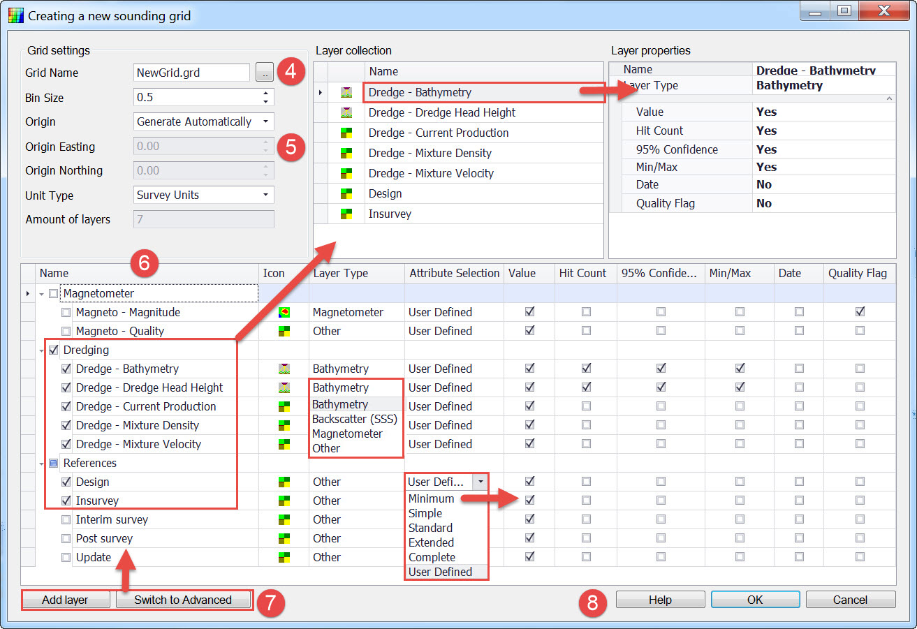


Those layers are copied to the Layer Collection window.
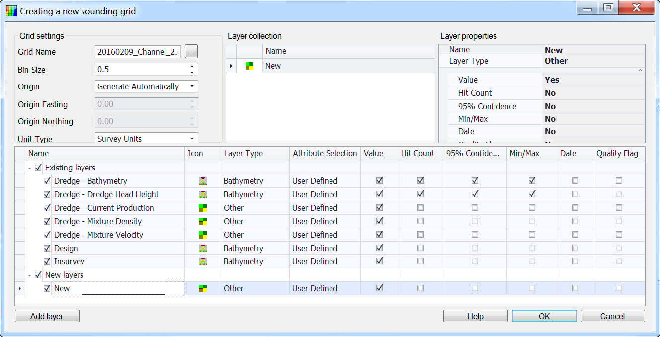
Choose the Layer Type and Attribute Selection for each activated layer. The number of attribute boxes checked depends on which attribute level is selected. For example, attribute Minimum checks only the Value tick box.
User Defined allows you to check whichever attributes you want.
As you highlight each layer in the Layer Collection window, its selected attributes are listed under Layer Properties.
The default names and Layer Types of the suggested layers can also be configured

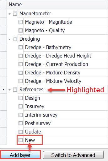
A new layer called 'New' is created under the highlighted layer type. Edit the name if necessary.
Adding an extra layer can also be done by right-clicking on the category where an extra layer is required and selecting Add Layer in the right-click menu.
Click on 'Switch to Advance/Switch to Normal' to change the layer listing. See table above for explanation.
The completed grid is displayed in Session Setup - Storage - Sounding Grid.
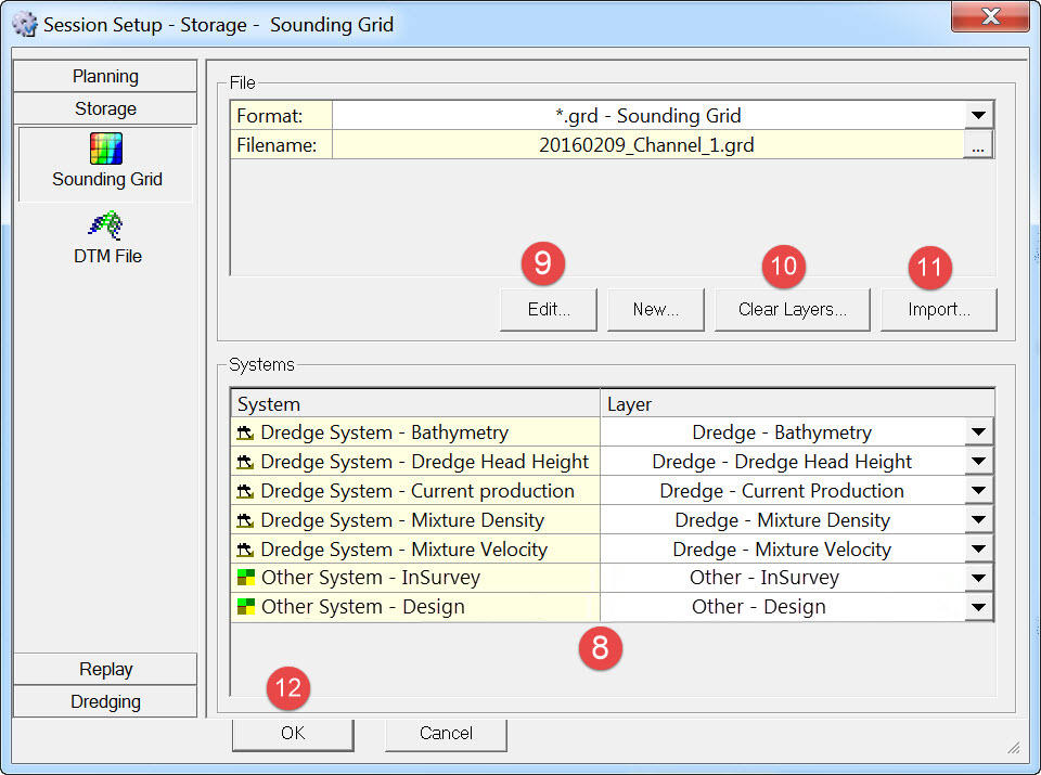

None of the Existing layers are editable.
The Add Layer button is live and any new layers added are editable in terms of layer type and attribute selections.
Grid Settings can be modified.


Source File Type: select either Points File or QPS Grid File
Source File: browse to the required file.
Target Layer: all the previously defined layers are listed.
Import Mode: choose between Overwrite Existing Data and Merge with Existing Data.

Return to: top of page.
How to use the old sounding grid dialog instead of the Create Sounding Grid application
If preferred the older sounding grid dialog can be used when Online. It requires a registry setting change:
Open the Controller - Session Setup - Storage - Sounding Grid page once. Then close the Controller.
The registry key with default value is now added to the registry.
Open the registry settings by pressing the Windows key and typing Regedit in the search box.
-
In the Registry Editor, click Edit -> Find...
-
Fill in: Allow Legacy SoundingGridDialog
-
Right-click on it, and select Modify
-
Its default value is 0000 00
-
To enable the new app, change it to 0000 01
-
Click Ok, close the Registry Editor
|
Registry Setting Name |
Value |
Effect |
|---|---|---|
|
Allow Legacy SoundingGridDialog |
0000 00 |
Default. Create Sounding Grid application is used. |
|
Allow Legacy SoundingGridDialog |
0000 01 |
Old Controller dialog is used. |
Relaunch the Controller - Session Setup - Storage - Sounding Grid page.
The Edit button is now disabled since it can only be used with the Create Sounding Grid application.
The New button now launches the old dialog.
The former application is used by default when creating a new grid in the Processing Manager, and when using the stand-alone program, i.e. \Program Files (x86)\QPS\QINSy 8.1\SoundingGridUtility.exe.
Return to: top of page.
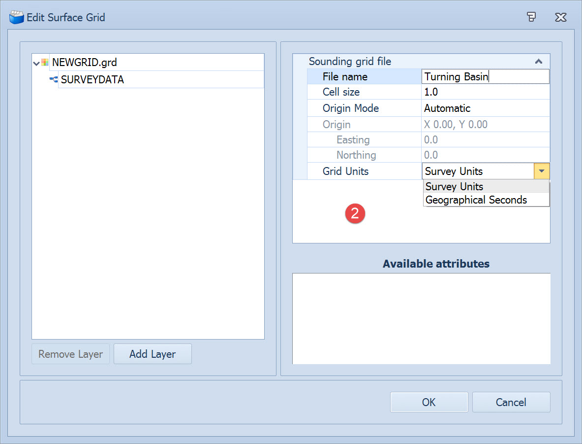
Processing Manager - File - New - Sounding Grid
|
Sounding Grid File |
|
|
|---|---|---|
|
File name |
By default the new grid is named NEWGRID. Change this by entering a different name. The name on the left is then updated. |
|
|
Cell size |
Enter a value for the base cell size (Reminder - an additional 5 grid layers are created with increasing cell size)
|
|
|
Origin Mode |
Automatic |
Centers the grid around the very first point that is imported or that is written to file during acquisition. The algorithm to calculate the origin will always result in an origin which is a factor of n x cell size relative to 0,0 in both directions. Example: Easting = 75498.367
75498.367 / 0.3 = 251661.22333.
|
|
User Defined |
Manually input the center coordinates. |
|
|
Grid Units |
Survey Units |
As set in the template database (Database Setup). |
|
Geographical Seconds |
Grid is defined by geographical coordinates Latitude and Longitude. Be careful in setting the base cell size: 1 second of arc at 45 deg latitude is approximately 31m in latitude and 22m in longitude.
|
|
Clicking on this name opens a different dialog that controls the grid's layers.
|
Sounding Grid Layer |
|
|---|---|
|
Layer Name |
Change the default layer name by entering a new name in the text field. The layer name on the left is then updated. |
|
Layer Type |
Click on this line to activate the drop down menu.
|
|
Layer Configuration |
Click on this line to activate the drop down menu.
|
Click on 
Set the name, type and configuration for each new layer added.
Click OK to complete the grid definition.
Return to: top of page.
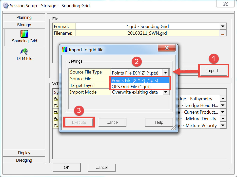
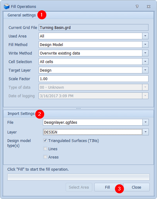
Importing a Design Model to a Sounding Grid
At the moment (Feb. 2016) there are three different options for importing a design model:
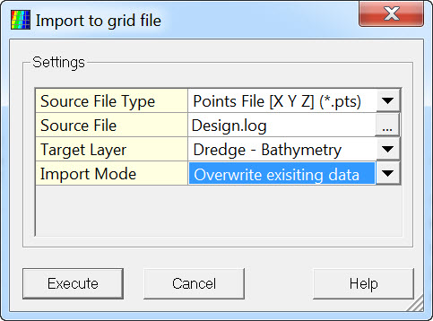
Controller - Settings - Session Setup - Storage - Sounding Grid (*.pts/*.grd)


|
File |
|
|---|---|
|
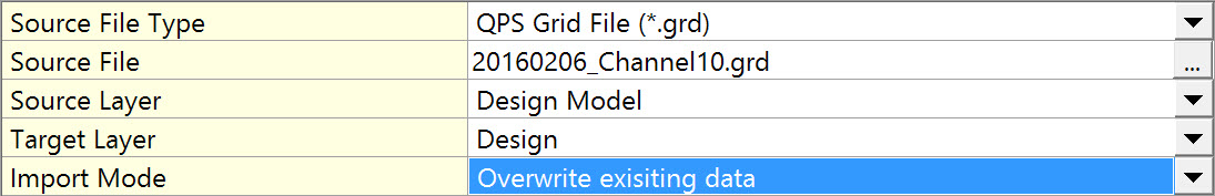
Source File Type |
Select either a Points File or a QPS Grid File from the pull down menu.
|
|
Source File |
Select the designated grid file by pressing the browse button. A standard MSWindows selection window will appear. |
|
Source Layer |
When importing from an existing grid file, specify the layer from which the data are copied.
|
|
Target Layer |
Select which layer to copy the source data to. |
|
Import Mode |
Overwrite existing data: the value in any cell already populated will be replaced with the imported value.
|


Return to: top of page.
Processing Manager - Grid Tools - Import (*.PRO)
Make sure the sounding grid you want to import to is already created with the layers you want.
Make sure the design model *.PRO file is loaded into the project or the import will not work. It can be loaded by importing
This file has some particular needs: please refer to Line Database Manager.
The design model in a *.pro file.
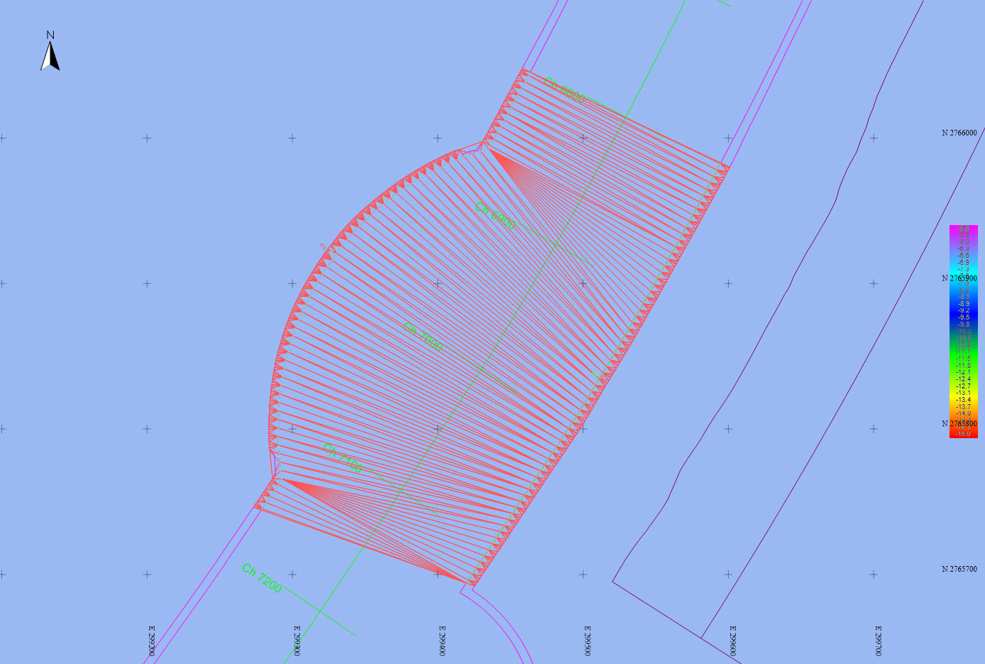
With the correct grid highlighted, click on Grid Tools and then on 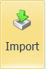
|
General Settings |
|
|---|---|
|
Current Grid File |
The grid file that was selected in the Project Explorer is shown here. It is the sounding grid to which the data are imported. |
|
Used Area |
All - All available space is used to import data into the grid, including data which might not currently be visible in the Project View.
|
|
Fill Method |
How should the grid be filled: with a Points File / Single Value / Interpolation / Extrapolation / Design Model / Geoid Model / Other Grid.
|
|
Write Method |
Overwrite existing data: the value in any cell already populated will be replaced with the imported value. Merge with existing data: the imported value for a cell will be added to the existing value and a new mean value is computed. |
|
Cell Selection |
Choose which cells should be filled: All cells: Any cell for which there is a value in the imported data is written into the SG layer. Whether the imported value replaces or merges with a previously existing value depends on the write method selected.
|
|
Scale Factor |
This is a multiplication factor which is applied to the data during import. For example if the original sounding points are in meters and you want to import soundings expressed in feet, enter the scale factor to convert feet to meters.
|
|
Target Layer |
Select the layer of the existing grid into which the imported data is to be written. |
|
Type of data |
Reports the system used to collect the data being imported.
|
|
Date of logging |
The date of collection of the data to be imported.
|
|
Import Settings |
|
|---|---|
|
File |
Select the Design Model file to be imported. The list contains only XML/DXF/PRO files that have been imported into the Processing Manager. |
|
Layer |
Choose which layer in the design model file that is to be imported. |
|
Design model type(s) |
Choose which type(s) of objects are to be used to create the design model. |
A progress bar indicates the status of fill operations. When Finished click close. The filled grid layer is now shown in the plan view.
Return to: top of page.
Stand alone SoundingGridUtility.exe
While this program is still available (Feb. 2016) it is being phased out. All its functionality is available in the other two grid creation programs.
Start the SoundingGridUtility.exe program located in the \\Program Files (x86)\QPS\QINSy 8.1 folder.
In the File menu open the sounding grid.
In the File menu select Import. This opens the Import dialog.
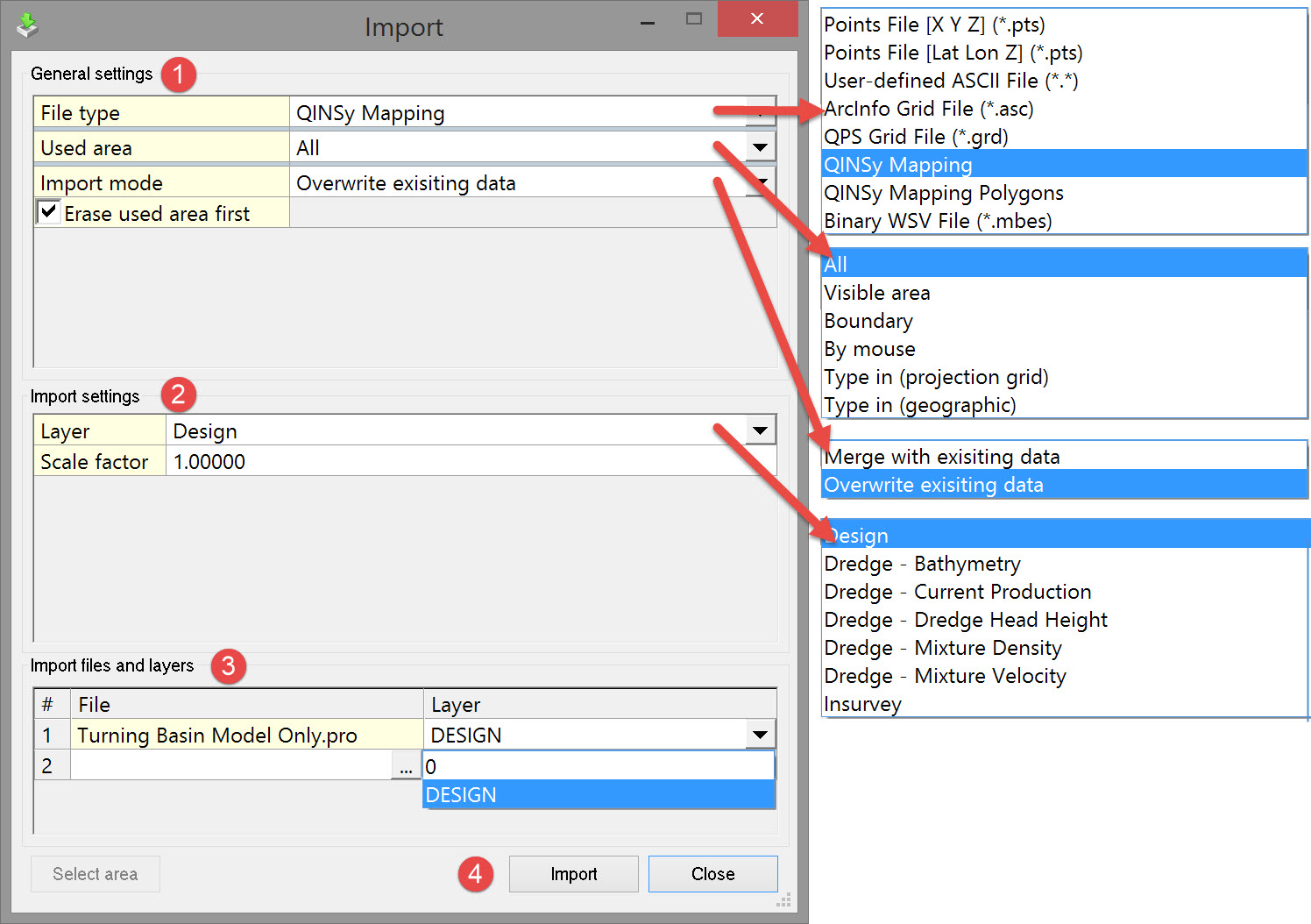
|
General Settings |
|
|
|---|---|---|
|
File Type
|
Select which type of file is to be imported. Points File [X Y Z] (*.pts) Points File [Lat Lon Z] (*.pts) User-defined ASCII File (*.*) ArcInfo Grid File (*.asc) QPS Grid File (*.grd) QINSy Mapping
Binary WSV File (*.mbes) |
Which types are available depends on the unit set during the creation of the grid file.
Space or comma delimited ASCII file. If the file to import or export is of a format not, by default, supported by the sounding grid utility and the file is in ASCII format, you have the option to define a new format for this type of data. An ASCII data exchange format text file for gridded data. This is a standard format for ESRI systems. Option to import a layer from another sounding grid file, only if cell size and grid origin are the same as the sounding grid to which the data is imported. A file format output by the Line Database Manager (LDM) which currently (Feb. 2016) uses the Terramodel ToolPak. This is being phased out, probably when the Line Planning functionality in the Processing Manager has the same user experience and functionality as the old LDM. A *.PRO file consisting of polygons only. Specific format used by WSV (The Waterways and Shipping Administration in Germany). The format description can be found in the Controller's Session Setup. |
|
Used Area |
All Visible Grid Boundary
Type in (Geographical) |
All the data in the particular file type is imported irrespective of the extents of the plan view. Only the data that fits into the current extents of the plan view is imported from the particular file type being used. Only the data that fits into the extents of a defined polygon is imported from the particular file type being used. The polygon representing the boundary is selected from a line database file (*.PRO)..
Enter minimum and maximum values for Easting and Northing. Enter minimum and maximum values for Latitude and Longitude. |
|
Import Mode |
Overwrite existing data Merge with existing data |
The value in any cell already populated is replaced with the imported value. The imported value for a cell is added to the existing value and a new mean value is computed. |
|
Import Settings |
|
|---|---|
|
Layer |
Select the layer in the open sounding grid file TO which the imported data are written. |
|
Scale Factor |
Option to re-scale the imported data during the import process. |
|
Import Files and Layers |
|
|---|---|
|
File |
Select the file FROM which the data are imported. |
|
Layer |
Select the layer in the source file on which the source data are stored. |
Return to: top of page
Return to: How-to Dredging