How-to Monitor - Touchdown Layback Tolerances
Page contents:
Introduction
A Touchdown Monitor can be setup Online in the Controller via the session setup
Visualizing the results of the monitor can be done in various displays and allow to user more get more insight and awareness in the Touchdown process
The Monitor results can be logged to files using the Generic Logger Online to meet the requirements of the project.
Integration with other processes could by done using Generic Output Drivers, which can be setup using Generic Layout Editor.
Controller - Session Setup - Monitoring
In the Controller - Settings - Session Setup the parameters for Monitoring can be set:
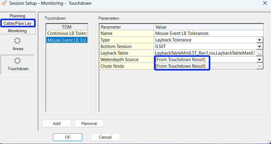
Only updating the Layback Tolerances (circles)
on Mouse Event
The monitor currently uses a Water Depth input as a source to define the minimum and maximum layback tolerances which can be monitored and visualized around the defined chute node.
The Water Depth Source (input) can be either :
From Touchdown Result (see Cable/Pipe Lay)
The Active Grid at:
Object Node location
Active Route KP - From Projected Node Location
The Current Route Z component - From Projected Node Location
Add a monitor
The Monitor list will be empty at start-up.
Select Touchdown on the left side under Monitoring
Use the Add button to create a new monitor.
Enter the following settings:A Name for the monitor.
Select the Type of the monitor: “Layback Tolerance”.
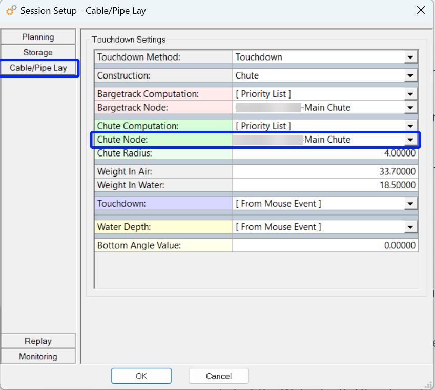
Chute Node
[From Touchdown Result] (Default)
Uses the results from Cable/Pipelay
When the “Touchdown Water Depth Source” has a different option selected than the default
[From Touchdown Result]:Select Chute Object (Most likely your Cable Lay Vessel object)
Select Chute Node
Only show the nodes from the Chute object
Touchdown Water Depth Source:
The Water Depth Source (input) can be either :
[From Touchdown Result] (Default)
The position and depth will be taken from the touchdown point that is setup in the Cable/Pipe Lay.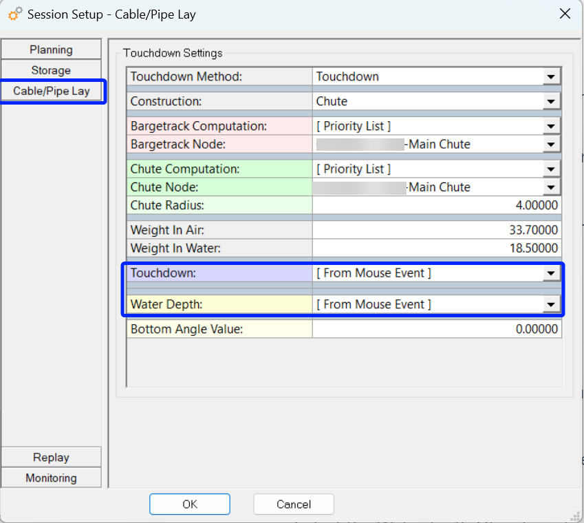
Other options
When a grid or a route is selected the depth will be taken from those at the location of the Water depth Node.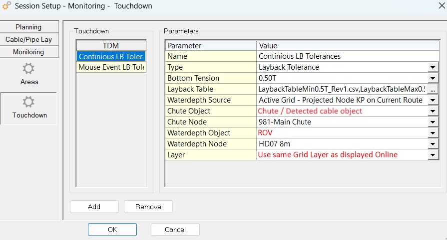
Continuous updating the Layback Tolerances (circles)
using depth at Route KP related to ROV nodeSelect the Waterdepth Object, probably the ROV hovering flying near the touchdown point.
Select the Node on the bottom object which will be used in the calculation.
Press OK to start the calculation.
Bottom Tension
The display offers the option to define multiple bottom Tension scenario’s using layback tables. These scenario’s and the required layback tables can be depending on the type of cable being laid, expected current, bottom slope.
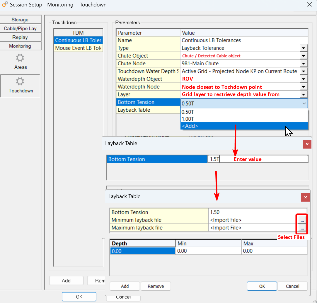
Adding Bottom Tension scenario’s and related Layback Tables
The Layback table is a lookup table that's using the actual depth.
Example of an Layback table file:
#Bottom Tension 1T,
Water depth,Min Layback
1,18
2,18.5
3,19.7
4,20
5,22.1
etc.
The water depth is the actual water depth at that moment.
In other words: Water depth = Chart Depth + Tide
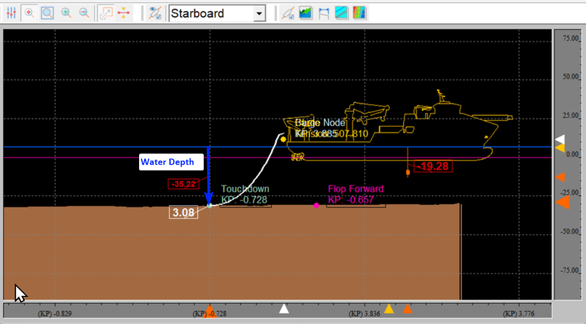
We will search the layback tables for the closest depths for both minimum and maximum layback and calculate (interpolate) the resulting layback (tolerance) value for each.
The layback tolerance values will be used to monitor if the Water Depth Source location:
From Mouse Event;
Node of the Water depth Object;
is within the calculated layback tolerances
Displays
Navigation Display
The Layback Tolerances are drawn as circles and are only drawn when there is a (possible) touchdown point known since the circles are drawn based on the depth at the Touchdown location.
The Color of the Layback circles can be changed in the View Properties of the Navigation Display in the Monitoring tab.
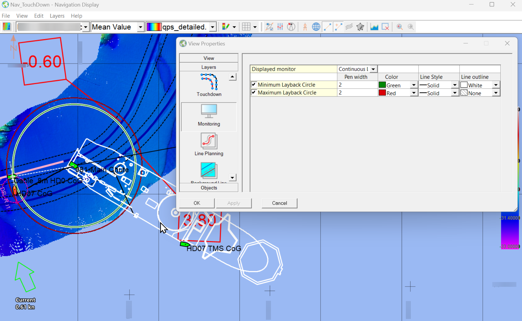
It is possible to setup multiple monitors however the navigation display will only show one at a time.
Be aware which monitor you are displaying, to prevent confusion with different types of alerting that can be setup (see example below).
Alert Display
Alerts can be added for the Computation Results of the Monitoring of the Touchdown Layback Tolerances
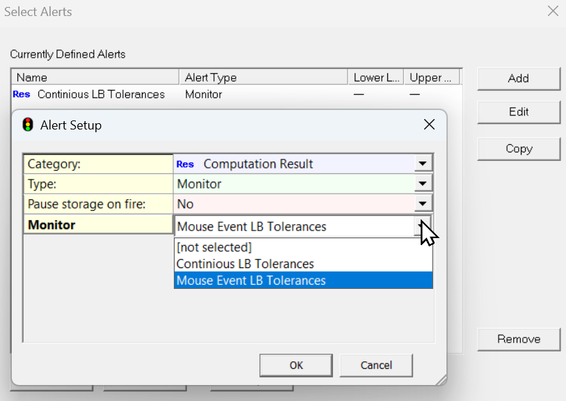
When the Touchdown point is in between the layback circles the alert is green (showing OK).
When the Touchdown point is not between the layback circles the alert is red (showing Alarm).
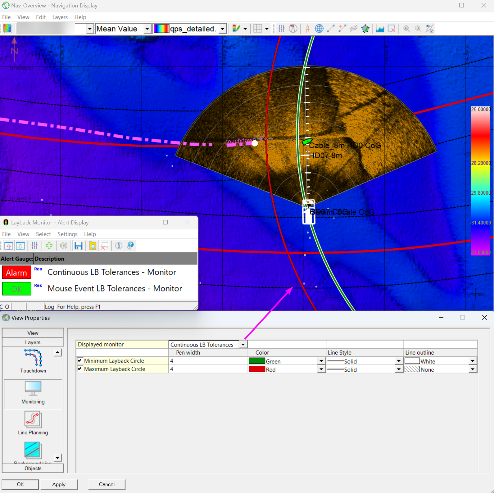
Monitor Alerts and shown Touch Down Layback Tolerances
In the example above we show the Touchdown Layback Tolerances for continuous updating using the depth at the KP on the Route from Node in front of the ROV.
The selected Node of the ROV is outside the tolerances and triggers the Alert for the “Continuous LB Tolerances - Monitor”.
The Alert for the “Mouse Event LB Tolerances - Monitor” is still green, because the moment the mouse trigger (Ctrl + Left Mouse in the Navigation Display) took place the mouse pointer was within the Touchdown Layback Tolerances for the “Mouse Event LB Tolerances - Monitor” and the “Continuous LB Tolerances - Monitor” at that moment in time.
The defined “Mouse Event LB Tolerances - Monitor” only updates the circles when there is an update from The Touchdown Result and not selected to be showing the circles in they above Navigation Display
Generic Logging to file(s)
The Monitor results can be logged to files using the Generic Logger Online to meet the requirements of the project. Generic Logging is automatically added to your template setup when you created a template and can be found in the Controller - Session Setup - Storage - Log File.
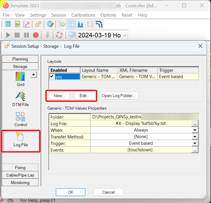
Generic Output Drivers
Integration with other processes could by done using Generic Output Drivers, which can be setup using Generic Layout Editor and by adding a Generic Output driver to your setup.
If you have added a Generic Output Driver to your setup, you can also define or alter the layout only from the Graphical User Interface of the driver Online.
