
Output System
Numerous predefined drivers allow output from QINSy of all kinds of data, both raw and results.
When systems are interfaced directly to the software, the most likely data to be output are to the dredger's PLC:
-
Position
-
Gyro
-
Pitch/roll
-
Depth
There are many existing drivers available, both serial and network (UDP and TCP).
Some comply with internationally recognized standards (e.g. NMEA) and others are proprietary (e.g. IHC Dredging Positions)
Which driver depends on the data type and the format that the PLC dredging software can decode.
In the event that a required format is not yet supported in the software, the Generic Layout Editor is used to write a custom ASCII output message using the:
-
Generic User-defined ASCII Output driver via serial, UDP or TCP. The Driver Layout XML file must be saved in subfolder \Drivers\Definitions\Output of the QINSy Public Files folder: C:\Users\Public\Documents\QPS\QINSy\Drivers\Definitions\Output
More specialized outputs include:
-
IHC Dredging Triangles
-
Waypoints
-
Auto-pilot
-
Tug Manager for anchor handling situations
If certain data are to be stored to file, the Generic Layout Editor is used to write a custom ASCII output message using the:
-
Generic ASCII Data Logger driver. The Log File Layout XML file is saved in subfolder \XML\LogFile of the current Project's Settings folder, or in the current Support Settings folder.
Please refer to the Drivers & Interfacing Manual, and to the QINSy Knowledge Base for more information regarding the .
The Generic Layout Editor can also be used to:
-
To create Displays when Online
The Display Layout XML file is saved in subfolder \XML\Display of the current Project's Settings folder, or in the current Support Settings folder -
To Export data after acquisition
The Export Layout XML file is saved in subfolder \XML\Export of the current Project's Settings folder, or in the current Support Settings folder.
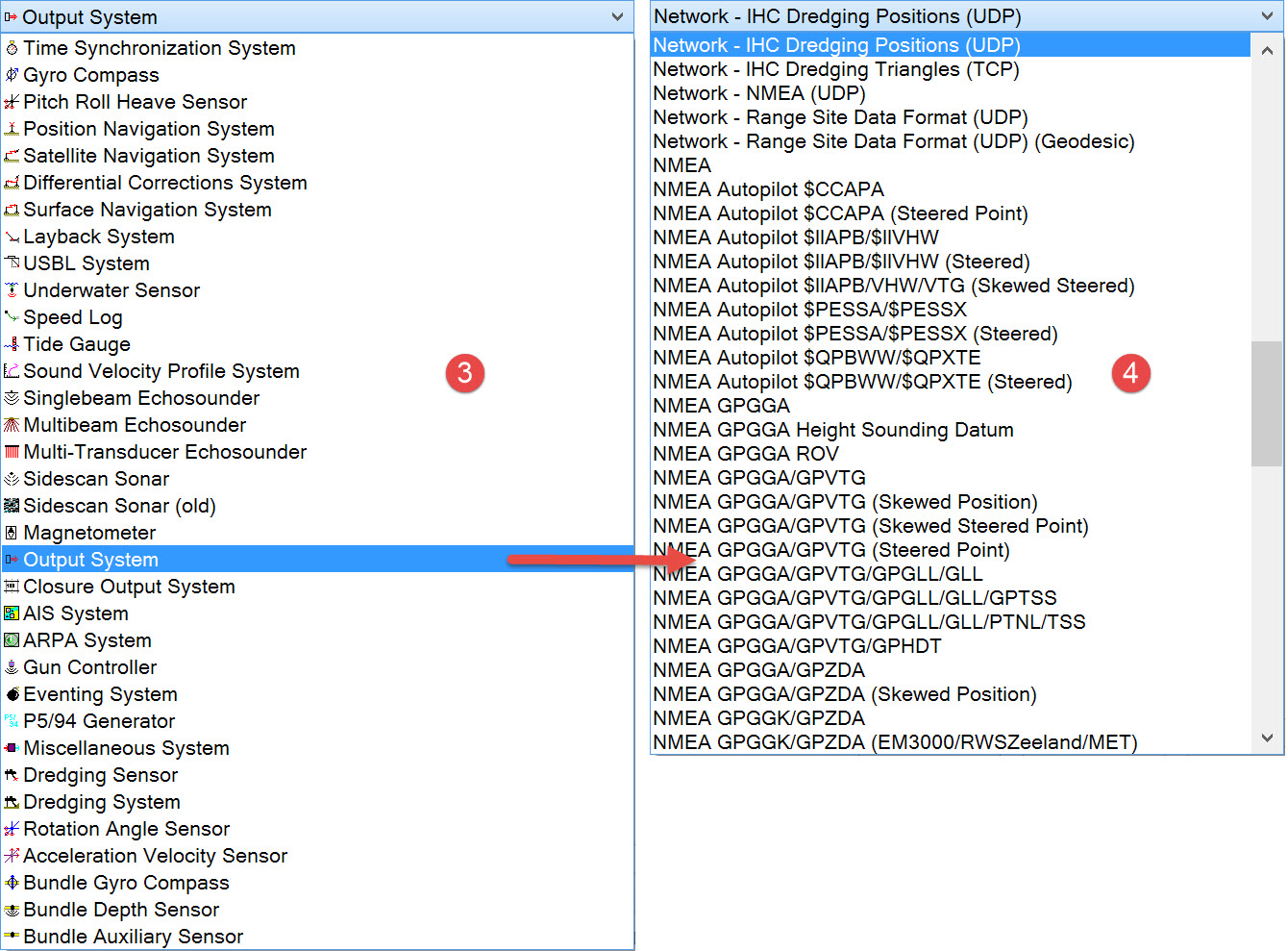
Two output drivers are described here.
The first (Network - IHC Dredging Positions), while specific to an IHC PLC, is just used as a demonstration of any output driver, all of which have a single page of parameters to define.
The second driver (Network - IHC Dredging Triangles) is a special output to an IHC PLC.
Network - IHC Dredging Positions (UDP)

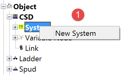
The following dialog opens.
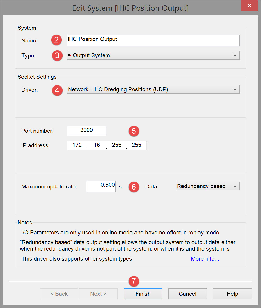


Please refer to A Note on Interfacing Parameters.

|
Updates |
|
|---|---|
|
Maximum update rate |
Enter a value to determine how often data will be decoded by the interface driver. Some equipment is capable of outputting data at high output rates, but it may not be necessary to use each update. A sensor system may for example output values hundreds of times per second, where five times per second is sufficient. In this case, enter a value of 0.20s. Any data not decoded by the driver is lost and cannot be recovered later. |
|
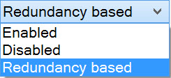
Data
|
Some output drivers can make use of the Redundancy functionality (refer to Redundancy Monitor system in the Drivers & Interfacing Manual). If so this option is shown on the first page of the setup wizard. The option can be Enabled/Disabled or set to Redundancy. This setting can also still be changed online.
The purpose of the Redundancy Monitor System driver is to perform an election process which decides which QINSy system is the primary system for data output.
|

Return to top of page.
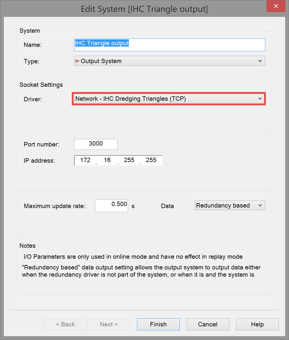
Network - IHC Dredging Triangles (TCP)
This driver outputs a number of TIN triangles from the currently selected dredging design surface. A request for a number of TIN triangles is made by the IHC dredging computer via a TCP/IP connection. The driver fetches the triangles from the design (manual, DTM/pro or Grid) and sends them to the IHC computer. The driver will select the triangles which are located in an area around the last node position.
When a Manual design is used the driver will send two triangles that represent an area of 500x500 survey units around the node position.
When DTM/pro file is selected the actual triangles as defined by the user in TerraModel are retrieved from the file.
When Grid file is used as input then the grid points are triangulated inside the driver and sent to the IHC computer.
Optional Session Setup-Dredging-Clipping Depth is not applied to the triangles.
The set up of this driver is identical to the driver described above except that the driver selection is different.
Return to top of page.
Return to: Cutter Suction Dredger (CSD) - System Definitions