
Tide System Definition
In case you are not using a positioning system with an 'accurate' height status, you may need to define a Tide System as follows:

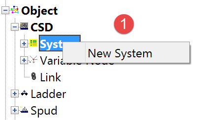
The following dialog opens. It is the first page of a wizard that steps you through the system definition process.
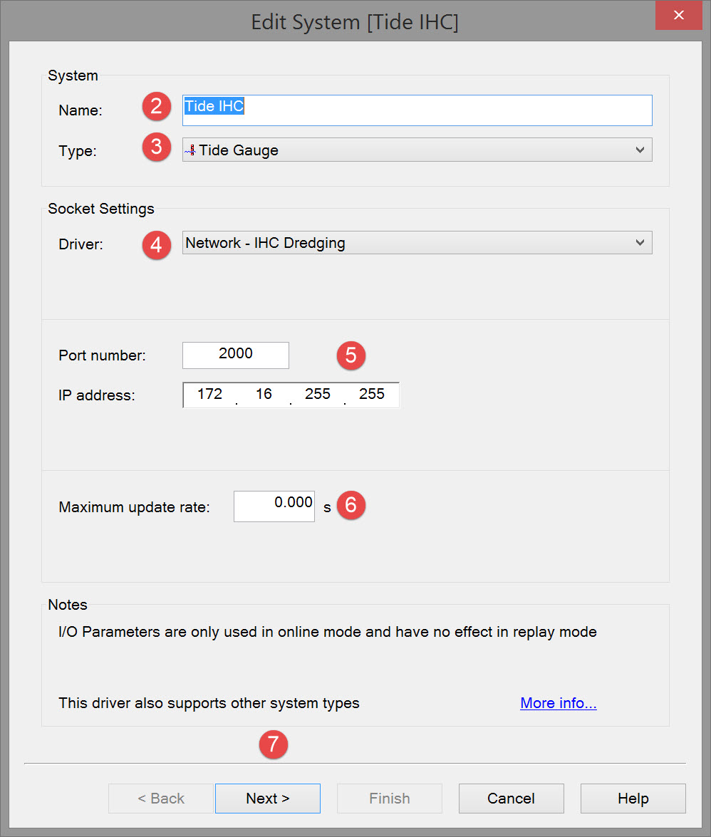


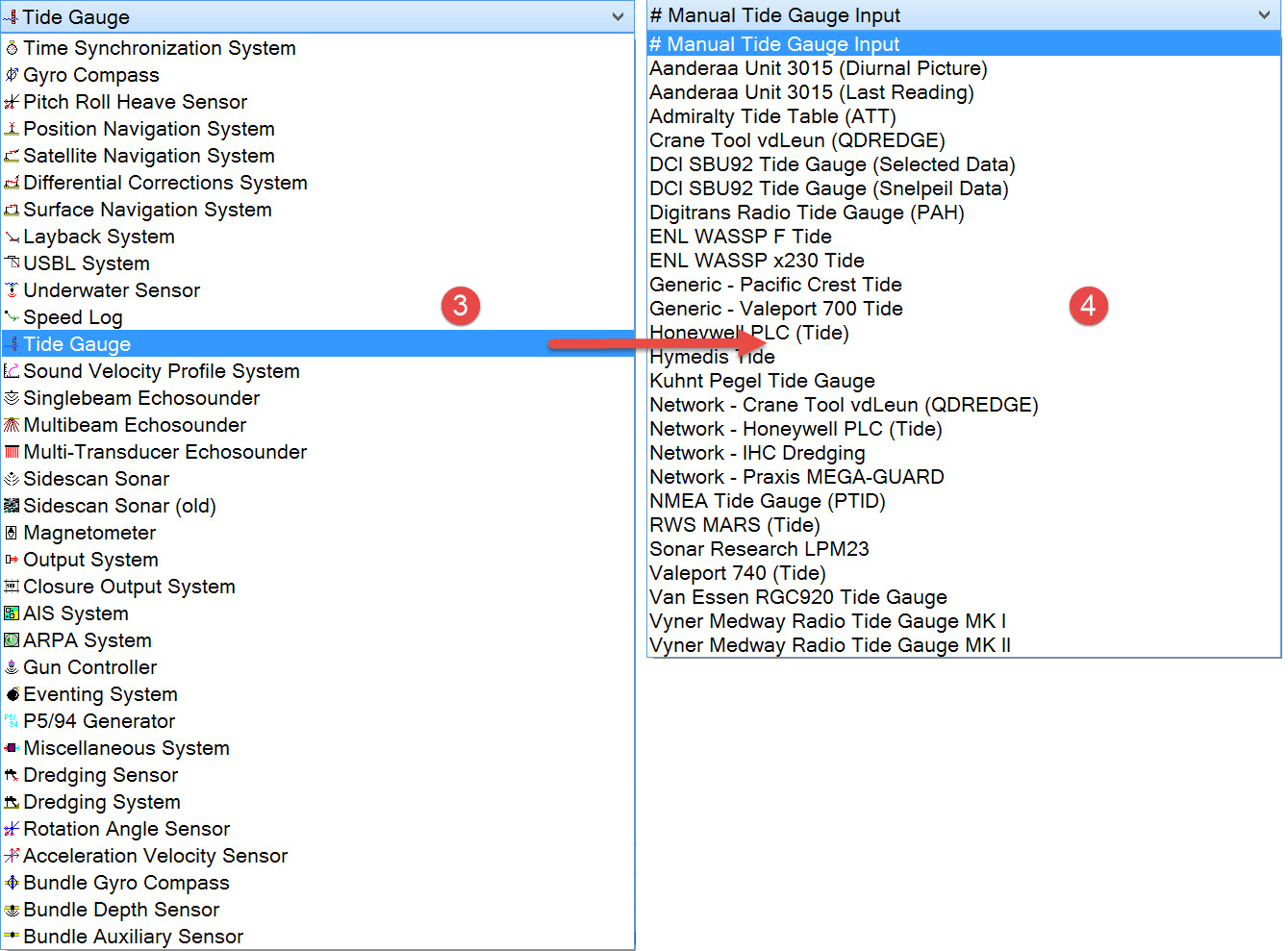

The driver list includes both serial and network drivers. If you have already defined other systems and some of the data messages are sent by the dredger's PLC, it is likely that tide data will also be issued by the PLC.

Please refer to A Note on Interfacing Parameters.

|
Updates |
|
|---|---|
|
Maximum update rate |
Enter a value to determine how often data will be decoded by the interface driver. Some equipment is capable of outputting data at high output rates, but it may not be necessary to use each update. A motion sensor system may for example output values hundreds of times per second, where twenty times per second is sufficient. In this case, enter a value of 0.05s. Any data not decoded by the driver is lost and cannot be recovered later. |
|
Latency |
Latency is the time between the actual measurement made in the motion sensor system and the time the data message arrives at the port. The time in QINSy will thus be the arrival time corrected with the latency.
|



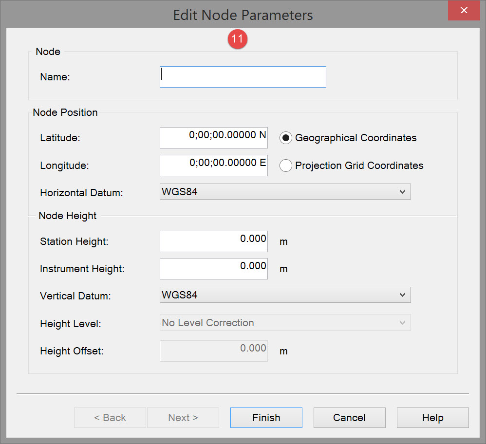

|
Node |
|
|---|---|
|
Name |
Enter a name for the node. |
|
Node Position |
|
|
Latitude / Easting |
Enter the latitude or easting coordinate. |
|
Longitude / Northing |
Enter the longitude or northing coordinate. |
|
Horizontal Datum |
Select a datum from the pull down menu. Usually coordinates are given on the survey datum. |
|
Node height |
|
|
Station Height |
Enter the station height above the vertical datum. |
|
Instrument Height |
Enter the instrument height above the station height. |
|
Vertical Datum |
Select the vertical datum. The options are identical to those in the Mean Water Level Model defined in the Geodetic set up. |
|
Height Level |
Correction to the vertical datum. The options are identical to those in the Mean water level model. |
|
Height Offset |
Enter a fixed height offset relative to the vertical datum if needed. |
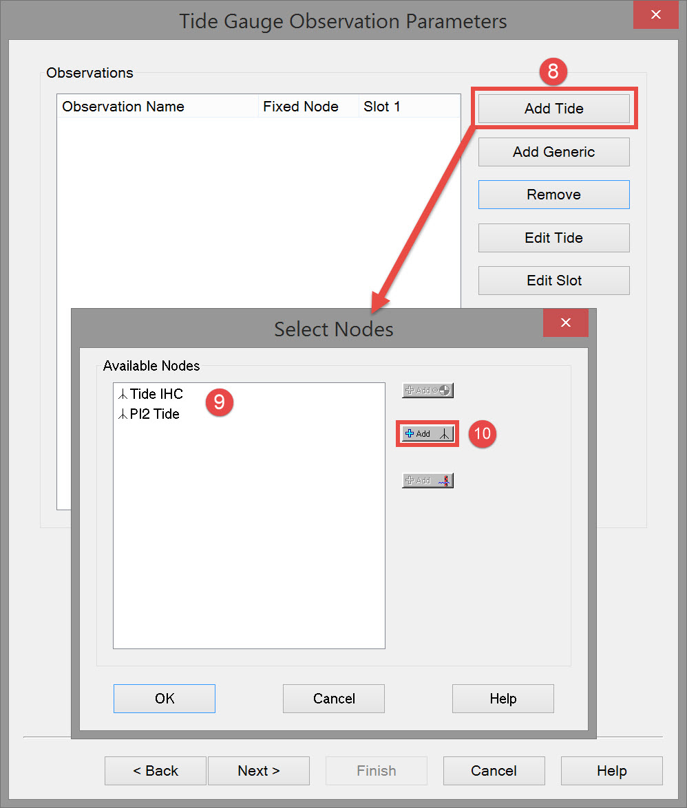
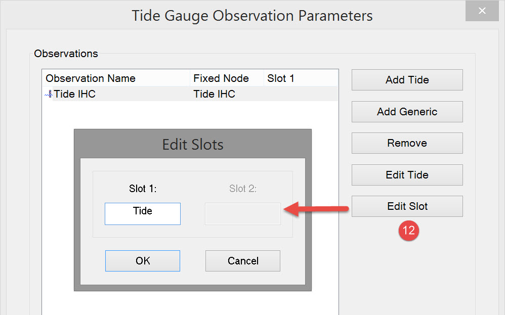
The Add Generic button in the Tide Gauge Observation Parameters dialog refers to:


Make sure the slot entry is exactly the same as the data message identifier or the tide will not be decoded. Click OK.

|
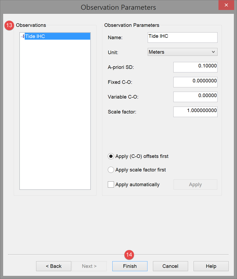
Observation parameters |
|
|---|---|
|
Name |
Enter a descriptive name for the observation. |
|
Unit |
Select the appropriate observation unit. In some cases there will only be one choice. |
|
a-priori SD |
Enter the SD for each observation in turn. |
|
Fixed C-O |
Constant correction to the parameter value. |
|
Variable C-O |
Variable correction to the parameter value. |
|
Scale factor |
Use scale factor to convert the raw output to units in the Acquisition Software.
|
|
Apply C-Os offsets first |
C-Os are added or subtracted before a scale factor is applied. |
|
Apply Scale factor first |
Scale factor is applied before C-Os are applied. |
|
Apply automatically |
The order in which corrections are applied is done in the software. |

Return to top of page.
Return to: Trailing Suction Hopper Dredger (TSHD) - System Definitions