
Miscellaneous System Definition
Various observations are definable under the Miscellaneous Systems category. For example: wind speed and direction, water temperature, TDS, water density, solid density.
On this page:
Using this system type in conjunction with:
-
a Dredging Sensor system decoding mixture density, mixture velocity, weight (displacement), volume, hopper levels, status and a flag (e.g. PMO status)
-
a USBL System to decode drag head positions
-
an Underwater System driver decoding vessel draft (fore and aft),
-
and the Dredging System where the dredger type is selected, density/velocity sensors are enabled, TDS and PMO calculations are enabled, nodes are allocated and observations are assigned.
.....it is possible to compute TDS in the software if it is not available from the dredger's PLC. The computation uses the generally accepted TDS formula used by "Rijkswaterstaat" of the Netherlands. This requires the hopper volume and current displacement from the data string as well as some user-defined fields. The user must define a KP versus water density / solid density table and the empty hopper displacement.
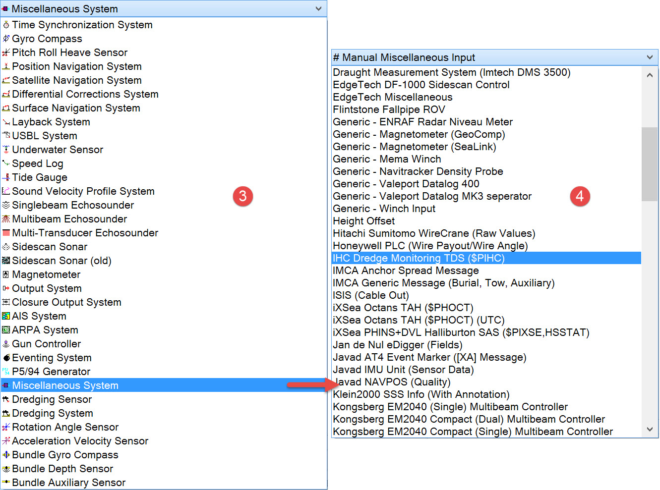
Some predefined drivers are available. For example, the IHC Dredge Montioring TDS ($PIHC) driver can compute the Tons Dry Solid (TDS) figure representing the load of the dredger. The following fields are decoded: USBL type X,Y,Z of the suction head, dredging status (8,9,10,3), displacement (11) and hopper volume (20) for TDS calculation.
Otherwise it is possible to use the IO Editor to write a user-defined driver to decode a data format not currently supported.
System Definition

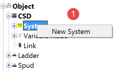
The following dialog opens. It is the first page of a wizard that steps you through the system definition process.
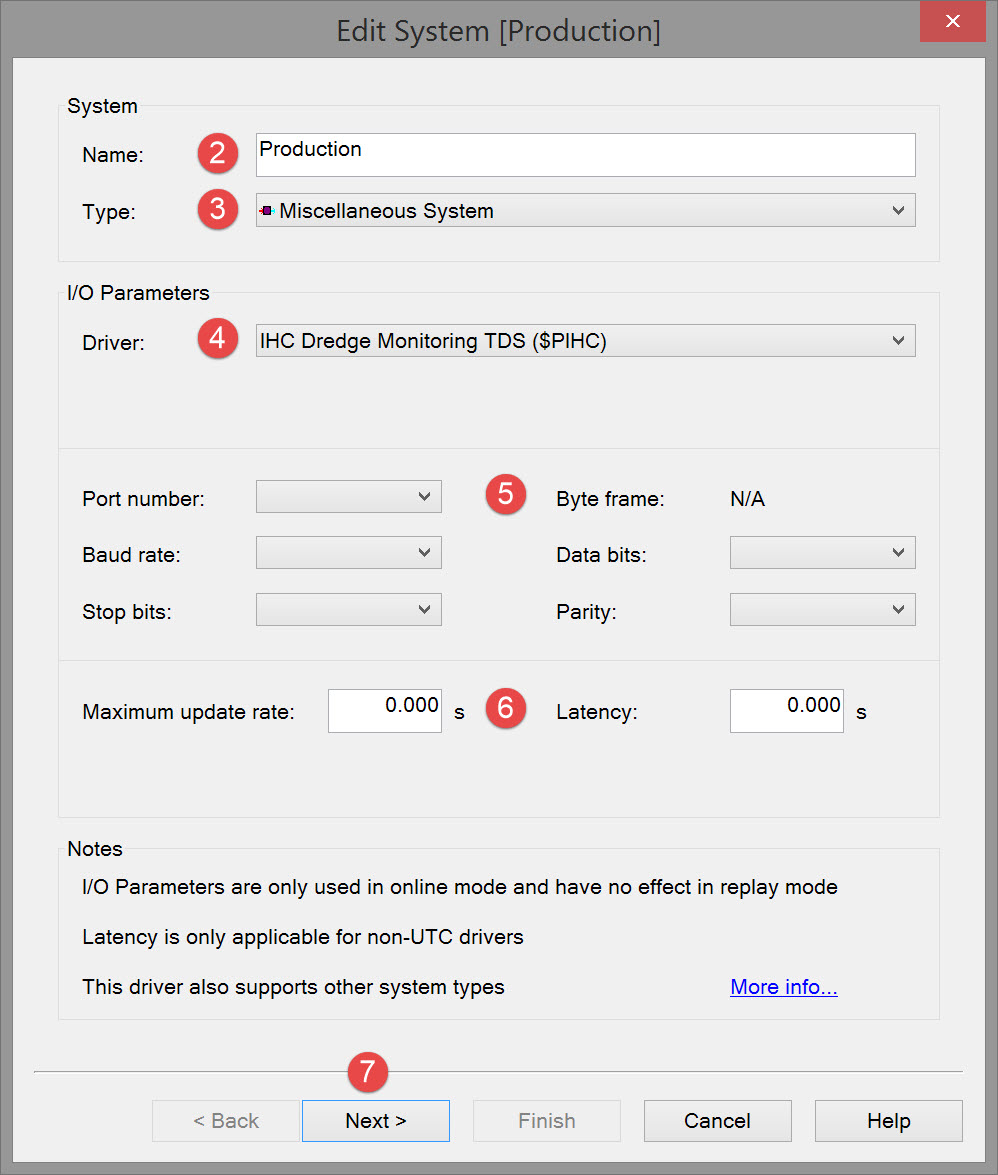


Note that the interfacing can be either serial or network so make sure to select the correct type.

Please refer to A Note on Interfacing Parameters.

|
Updates |
|
|---|---|
|
Maximum update rate |
Enter a value to determine how often data will be decoded by the interface driver. Some equipment is capable of outputting data at high output rates, but it may not be necessary to use each update. A sensor system may for example output values hundreds of times per second, where five times per second is sufficient. In this case, enter a value of 0.20s. Any data not decoded by the driver is lost and cannot be recovered later. |
|
Latency |
Latency is the time between the actual measurement made in the sensor system and the time the data message arrives at the port. The time in QINSy will thus be the arrival time corrected with the latency.
|


This is in order that the software can 'marry' the right data value to the observation.
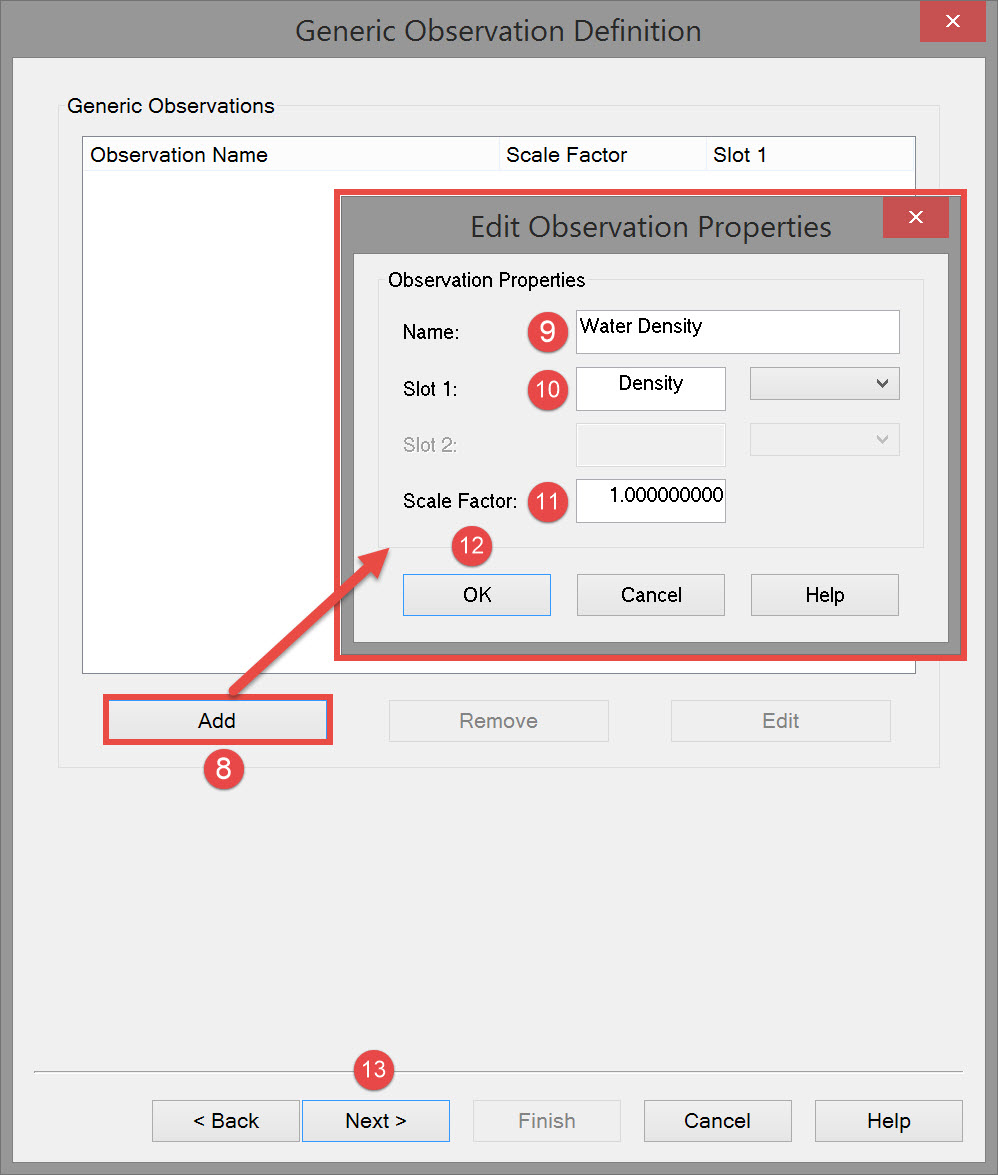
Enter the identifier in the Slot field. Note that the Drivers and Interfacing Manual has identifier listings for many of the Miscellaneous System drivers.


If additional observations must be defined, click on the Add button again and repeat the process. A final definition might look like this:
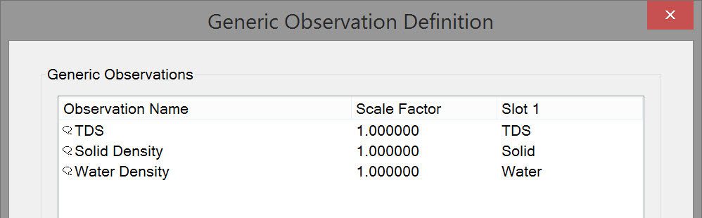
To change observation names and/or slots use the Edit button to reopen the Edit Observation Properties dialog.


|
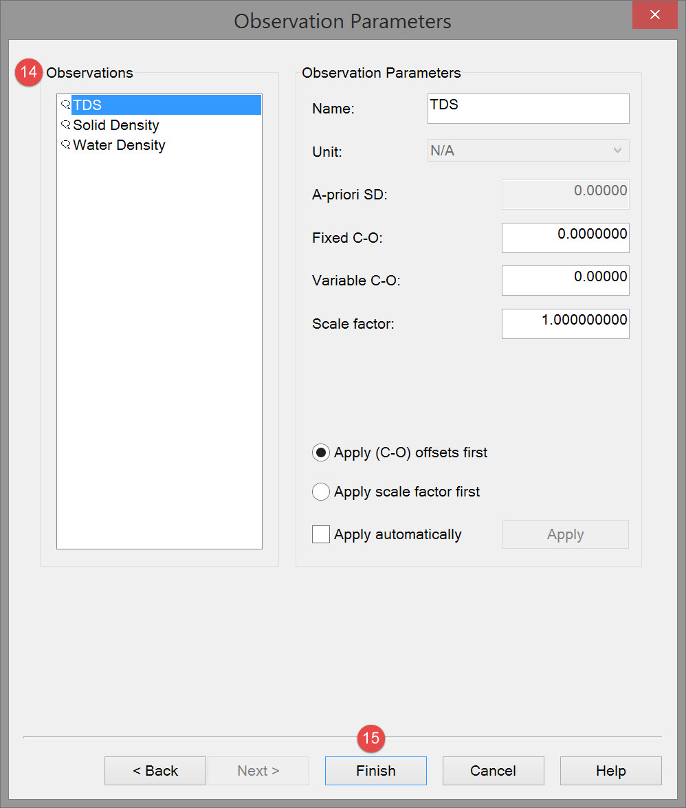
Observation parameters |
|
|---|---|
|
Name |
Enter a descriptive name for the observation. |
|
Unit |
Select the appropriate observation unit. In some cases there will only be one choice. |
|
a-priori SD |
Enter the SD for each observation in turn. |
|
Fixed C-O |
Constant correction to the parameter value. |
|
Variable C-O |
Variable correction to the parameter value. |
|
Scale factor |
Use scale factor to convert the raw output to units in the Acquisition Software.
|
|
Apply C-Os offsets first |
C-Os are added or subtracted before a scale factor is applied. |
|
Apply Scale factor first |
Scale factor is applied before C-Os are applied. |
|
Apply automatically |
The order in which corrections are applied is done in the software. |

Online Driver
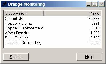
When a Miscellaneous System is defined with one or more of the observations (Current KP, Hopper Volume, Hopper Displacement (weight), Water Density, Solid Density, and TDS), a Dredge Monitoring driver window (see below) is displayed when going Online.
You must enter a KP versus Water and Solid Density table and the Empty Hopper Displacement value in Tons. Press the "Setup" button on the driver's window. This will show the Setup dialog as shown below:
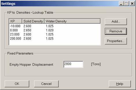
The driver selects/interpolates the appropriate densities from this table. It uses the KP value of the steered node with respect to the currently selected mainline as the input value.
If the table is empty then the TDS calculation is not performed. The Table is stored in the registry of the PC. These values will be automatically retrieved on start-up of the driver.
Main window Explanation:
If driver is properly set up and the positioning is valid then the figures as shown in the picture above will be refreshed whenever a new string arrives from the IHC dredging computer.
Explanation of fields in main window:
|
Current KP |
Shows calculated KP of steered node with respect to mainline |
|
Hopper volume |
Current volume of load in hopper (from IHC) |
|
Hopper displacement |
Current hopper displacement (from IHC) |
|
Water density |
Density used for TDS calculation, derived from current KP and user-defined table |
|
Solid density |
Density used for TDS calculation, derived from current KP and user-defined table |
|
Tons dry solid (TDS) |
Calculated TDS. |
Return to top of page.
Return to: Trailing Suction Hopper Dredger (TSHD) - System Definitions