
Dredging System
Define the Dredging Sensor System before defining this system.
Use the Generic Dredging System to select the type of dredger, activate production calculations, and determine origin of the status, i.e. from the Eventing driver or the onboard dredging computer.
Prior to defining a dredging system the observations that support the dredging system should be defined (usually part of a dredging sensor system type). For example the dredging status (e.g. dumping/dredging/sailing loaded), current measurement, open/close bay door observation etc. Note that this is optional, all the values can also be entered/overruled online.
This driver listens mainly to other drivers that do the actual interfacing. It generates Dredge Observations (triggers) that drive the dredging process; for example when either an update interval is reached (suction input/output) or when it detects an event from the Eventing system.
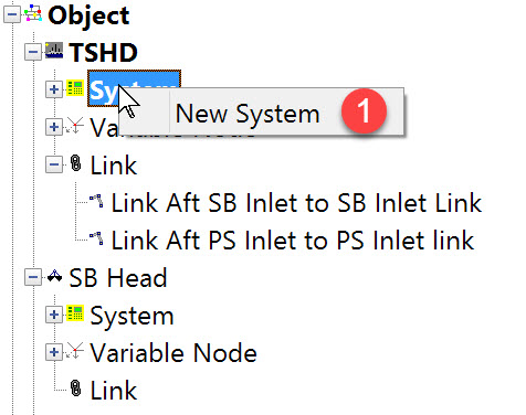

The following dialog opens. It is the first page of a wizard that steps you through the system definition process.
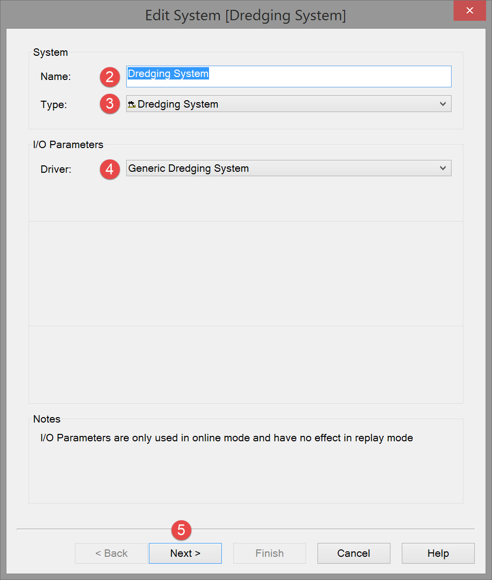


Check the TDS box to enable this calculation. TDS measures the volume and weight of the hopper load to determine the quantity of dry solids that the load contains.
By applying the values for the dry solid specific density and in situ water density in a formula with the hopper load weight and volume (which indirectly measures the average density of the hopper load), the total quantity of the dry solids can be calculated.
The data requirements for computing TDS are:
-
Density of in situ water
-
Specific density of dry particles
-
Hopper volume
-
Vessel (hopper) weight.
The draft of the vessel is the most important signal for the TDS system. This is determined by measuring the pressure at a point forward and another point aft of the ship.
The signal (mA) which comes from the pressure sensor is transformed into a 2-10 Volt or a 1-5 volt signal. This signal is measured and converted to the draft of the vessel in survey units.

Select if the status from the dredge computer is to be used or not. If it is set to “Status” Qinsy will use the status observation in order to update the grid. For instance if the drag head enters the seabed and the status isn’t set to dredging the grid will not be updated.
If Status is used, select “Translation” in order to set the correct status observation for each status. So if 'dredging' has a status of '1' and 'not dredging' a status of '0', enter '1' in the Dredging row.


|
Description |
Value |
|---|---|
|
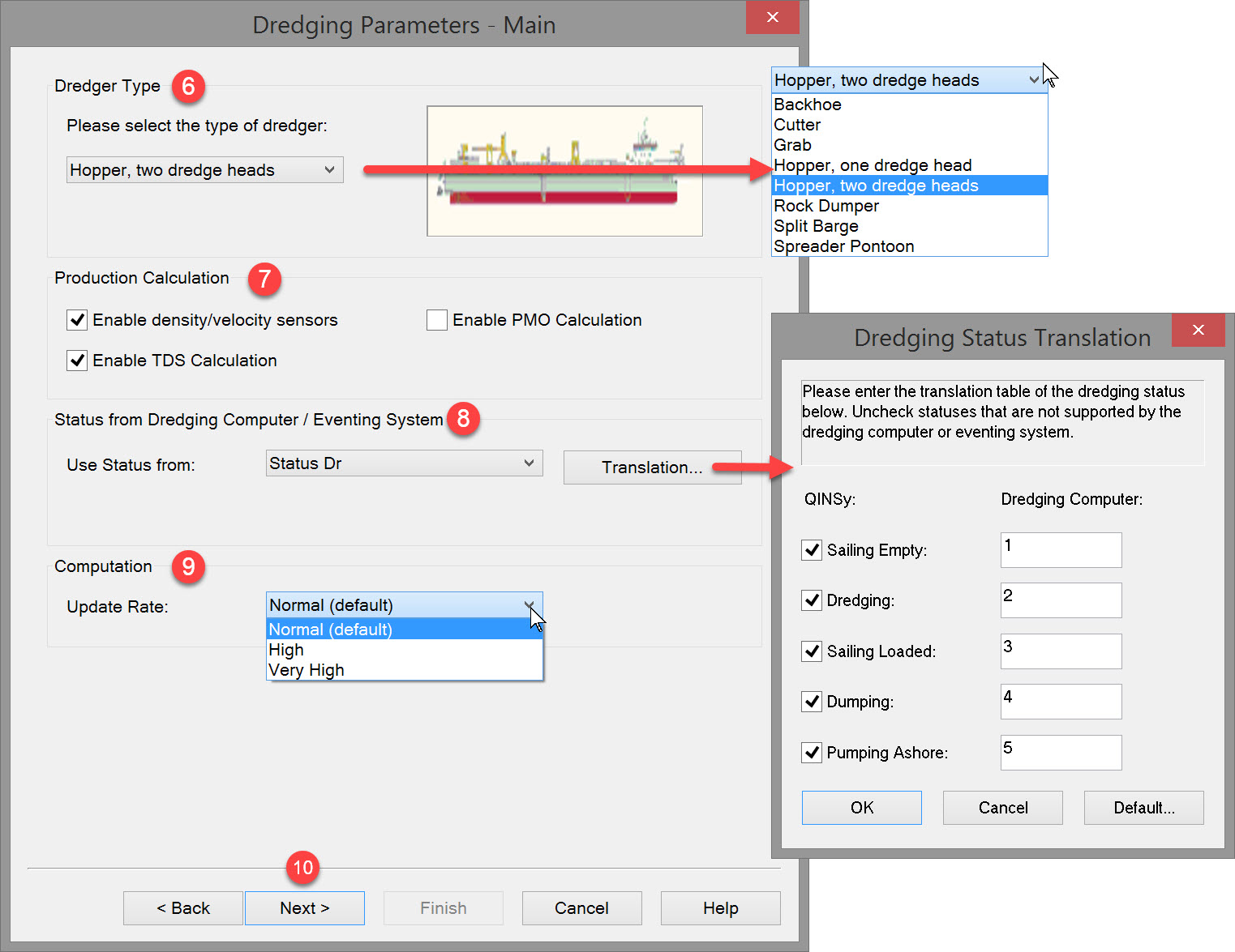
Dredge Head Node (1 & 2) |
Select the “Dredge Head Node” from the pull down menu. This is the node where the dredge head is attached to the suction pipe. |
|
Dredge Head Roll Offset |
The roll offset should be set to 0 degrees. |
|
Dredge Head Pitch Offset |
The pitch offset should be set to 0 degrees. |
|
Dredge Head Heading Offset |
The heading offset should be set to 0 degrees. |
|
Current Velocity (m/s) |
If a sensor is interfaced you can select it here or you can select Manual Input and enter the figures. Note the current direction that is expected is the true direction. Velocity in survey unit/sec.
|
|
Current True Direction |
The current observations can be used to calculate the settling location of the dumped material. The observations can be left at “Not Used” when only manual input of the current is required. |
|
Number of Bays |
Define the number of bays. Every bay is represented by a node position, width and height.
|
|
Bay 1 Center Node |
Every bay is represented by a node position at the center of the bay.
|
|
Bay 1 Volume |
In cubic survey units. |
|
Bay 1 Length |
In survey units. |
|
Bay 1 Width |
In survey units. |
|
Bay 1 Open/Close Switch |
Optionally a closed/open sensor can be defined by adding a new dredging sensor system for open/close sensors.
|
|
Bay 1 Dump Shape |
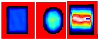
The dump shape represents how the dumped material should be visualized on the seafloor, and therefore how it modifies the sounding grid depths.
|


|
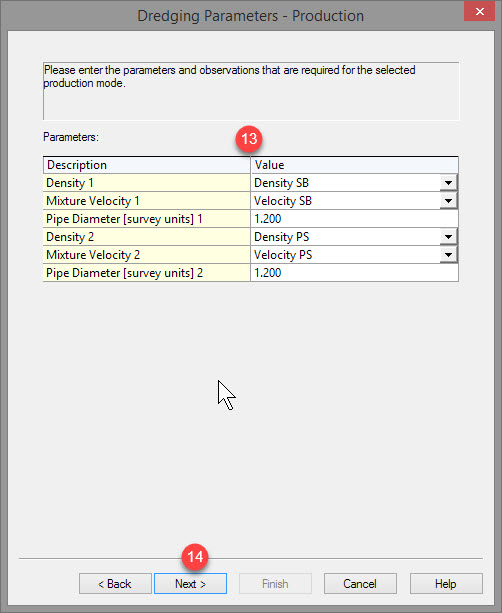
Description |
Value |
|---|---|
|
Density 1 |
Select the observation for Density, drag head #1. This observation must be defined in a Dredging Sensor System before it will appear in the list here. |
|
Mixture Velocity 1 |
Select the observation for Mixture Velocity, drag head #1. This observation must be defined in a Dredging Sensor System before it will appear in the list here. |
|
Pipe Diameter (survey units) 1 |
Enter the pipe diameter for drag head #1 using the units defined for the project. |
|
Density 2 |
Select the observation for Density, drag head #2. This observation must be defined in a Dredging Sensor System before it will appear in the list here. |
|
Mixture Velocity 2 |
Select the observation for Mixture Velocity, drag head #2. This observation must be defined in a Dredging Sensor System before it will appear in the list here. |
|
Pipe Diameter (survey units) 2 |
Enter the pipe diameter for drag head #2 using the units defined for the project. |
These values will be used for the production calculation.

|
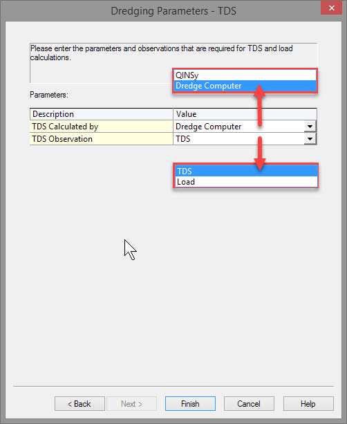
Description |
Value |
|---|---|
|
TDS Calculated by |
Choose either QINSy or the Dredge Computer |
|
TDS Observation |
Choose either TDS or Load (see below). |
Click on Finish to complete the Dredging System definition.
Return to top of page.
Return to Trailing Suction Hopper Dredger (TSHD) - System Definitions.
Load versus TDS
Basically there are two main methods for loading the hopper:
-
The ‘Constant Volume System’ (CVS). This system has a fixed overflow level so the effective volume of the hopper is constant. The TSHD is designed for filling the hopper with sediment with a density of 1.9-2.0 ton/m3.
-
The ‘Constant Tonnage System’ (CTS). The system has an adjustable overflow level. The hopper is designed for a density of 1.3-1.7 ton/m3 in combination with a maximum tonnage.
When the content of the hopper reaches the maximum tonnage, the overflow is lowered in order to keep the tonnage of the hopper content constant.
This system has certain advantages, like reaching the maximum tonnage sooner than with CVS, resulting in the pumps to be as low as possible, giving a higher mixture density.
The total load or gross load consists of the sediment with water in the pores and a layer of water or mixture above the sediment. The TDS consists of the weight of the soil grains only.
The net weight in the hopper consists of the weight of the sediment, including the weight of the pore water. If the porosity of the sediment is considered to be equal to the in-situ porosity, then the volume of the sediment in the hopper equals the removed situ-volume.
Although, in practice, there will be a difference between the in-situ porosity and the sediment porosity, if they are considered equal, the net weight (weight of the sediment Ws) is equal to the weight in the hopper Wh minus the weight of the water above the sediment Ww:
Ws = Wh - Ww
The net volume (volume of the sediment Vs) is equal to the volume of the hopper Vh minus the volume of the water above the sediment Vw.
Vs = Vh - Vw
Multiplying the volumes with the densities gives:
Vs . ρs = Wh - Vw . ρw and Vw = Vh - Vs
Vs . ρs = Wh - (Vh - Vs) . ρw
Vs . (ρs - ρw) = Wh - Vh . ρw
Rearranging the terms of equation gives an expression for the volume of in situ cubic meters
Vs = (Wh - Vh . ρw) / (ρs - ρw)
Multiplying the in situ volume Vs with the in situ density ρs gives for the in situ weight Ws:
Ws = Vs . ρs = ((Wh - Vh . ρw) . ρs) / (ρs - ρw)
To find the weight of the sand grains only (without the pore water), the situ density ρs has to be replaced by the
quarts density (or particle density) ρq:
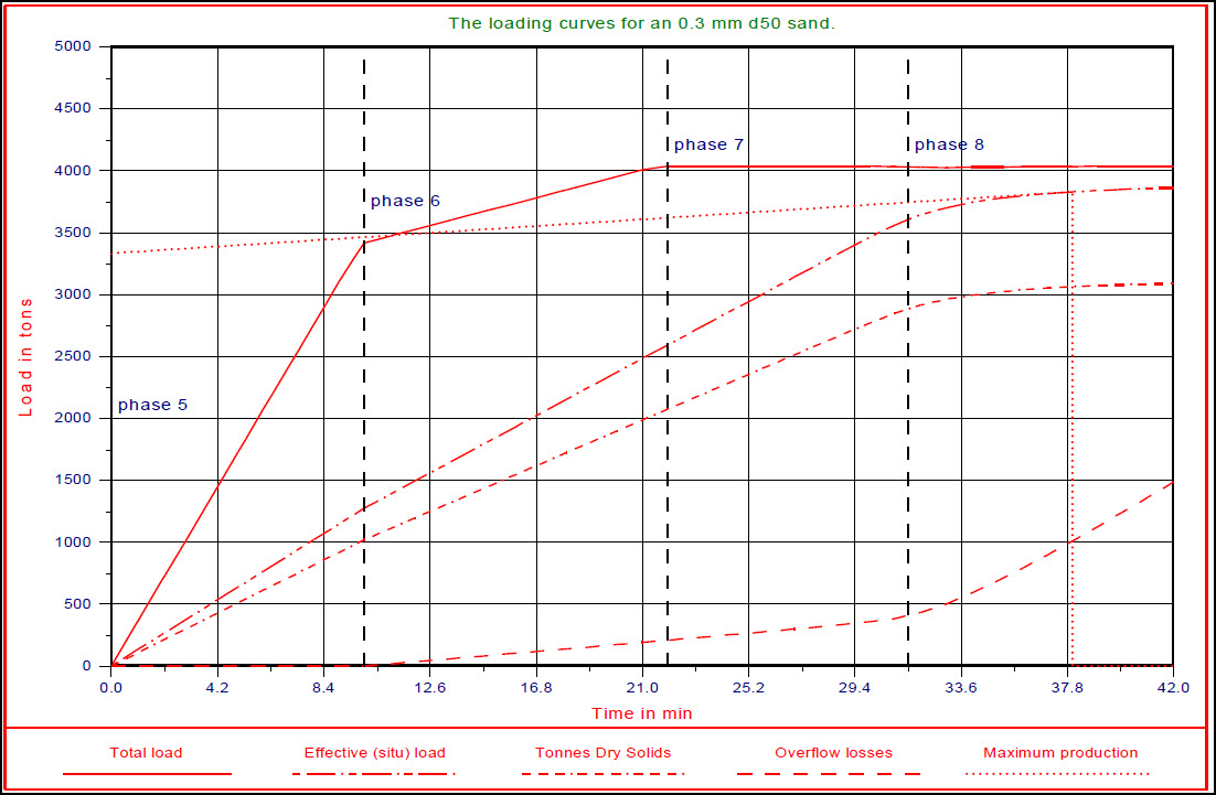
TDS = Ws . ((ρs - ρw) / (ρq - ρw)) . ρq /ρs = ((Wh - Vh . ρw) . ρq ) / (ρq - ρw)
With these equations the hopper cycle for the net weight and the TDS can be derived, per the figure below. The hopper dredge is optimally loaded, when the effective load (weight) or the TDS divided by the total cycle time dWs/dt reaches its maximum.
Return to top of page.
Return to: Trailing Suction Hopper Dredger (TSHD) - System Definitions