
Several different sensor types are used in computing the 3 dimensional dredge head position relative to the ship's reference point, and the position of the TSHD relative to the water surface. Position is determined by angle measurement, horizontally (X, Y) and vertically (Z).
Sensors include:
-
encoders to measure paid out length of middle gantry and drag head wires
-
electro-mechanical vertical sensors on upper and lower pipes, and gantry cranes
-
electro-mechanical horizontal sensors on the hinge parts of the pipes
-
pressure sensors for depth measurement of inlet and drag head
-
bubblers, the most common used method to measure level values in the dredging industry, although radar is also used for hopper levels
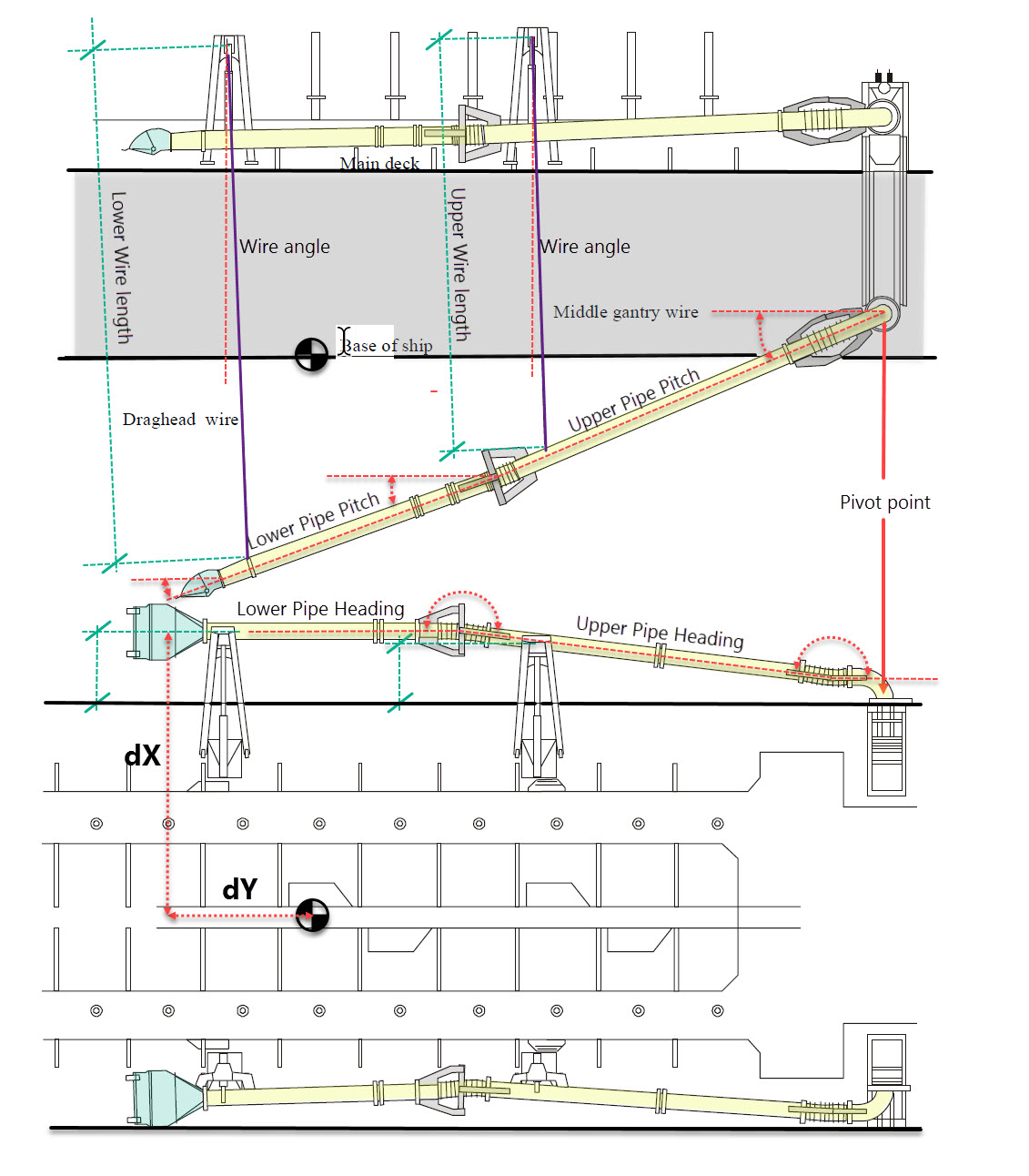
The diagram above indicates the types of distance and angular measurement needed to compute drag head position.
Vertical Position
-
Inclinometers
-
pressure transmitters
-
encoders to measure paid out length of middle gantry wire and draghead wire.
-
Bubblers
The vertical position of the drag head can be checked / calibrated by attaching a pressure sensor to the heel of the drag head. The depth of the drag head is directly proportional to pressure .
Horizontal Position
-
rotation angle sensors, designed for shaft angles or rotations and suction tube position angles, in the horizontal plane.
An angular position sensor (also referred to as a rotary sensor) measures the relation by which any position with respect to any other position is established. It calculates the orientation of an object with respect to a specified reference position as expressed by the amount of rotation necessary to change from one orientation to the other about a specified axis.
In most cases the sensors needed to compute drag head horizontal and vertical position are interfaced directly to the dredger's PLC, rather than to QINSy. Typically the drag head position is output from the PLC to QINSy as pseudo-USBL measurements (dX, dY, dZ) relative to the vessel's reference point.
If preferred the digital values for all these sensors can be output from the PLC and the position computation performed in QINSy. Decoding the values may require creating one or more XML drivers using the IO Editor.
Return to: Trailing Suction Hopper Dredger (THSD) - System Definitions