
Dredging Sensor Definition
Prior to defining a dredging system the observations that support the dredging system should be defined (usually part of a dredging sensor system type). For example the dredging status (e.g. dumping/dredging/sailing loaded), current measurement, open/close bay door observation etc.
Note that this is optional, all the values can also be entered/overruled online.
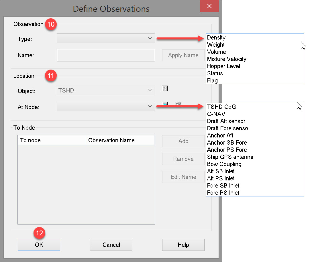
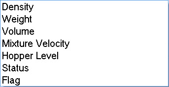
Observations associated with a Dredging Sensor are:
-
Density (of mixture)
-
Velocity (of mixture)
-
Weight (displacement)
-
Volume
-
Hopper Level
-
Dredging Status
-
Flag (e.g. PMO valve)
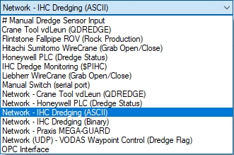
In addition to the various predefined drivers provided, the IO Editor may be used to write a driver to decode a currently unsupported data string.
The Dredging Sensor system works in conjunction with
-
a USBL System to decode drag head positions
-
an Underwater System driver decoding vessel draft (fore and aft),
-
a Miscellaneous System to define such observations as Solid Density, Water Density, Trim tank total. This driver also computes TDS
-
and the Dredging System where the dredger type is selected, density/velocity sensors are enabled, TDS and PMO calculations are enabled, nodes are allocated and observations are assigned.
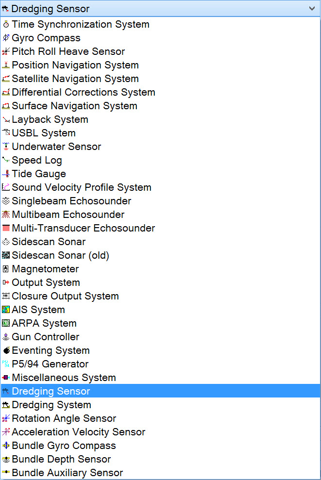
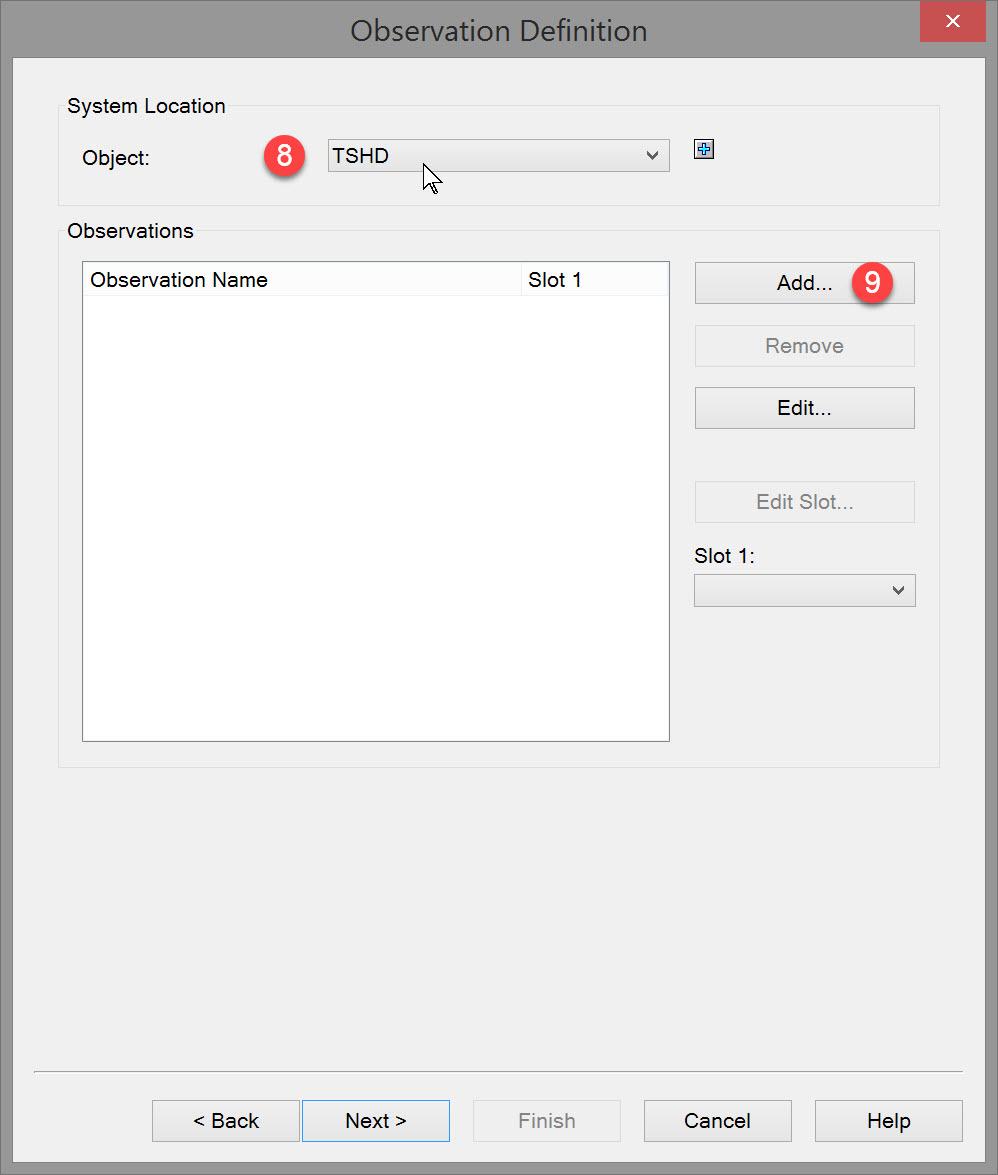
To define a Dredging Sensor:

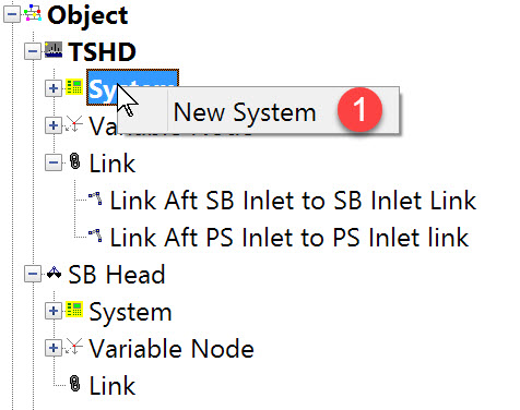
The following dialog opens. It is the first page of a wizard that steps you through the system definition process.
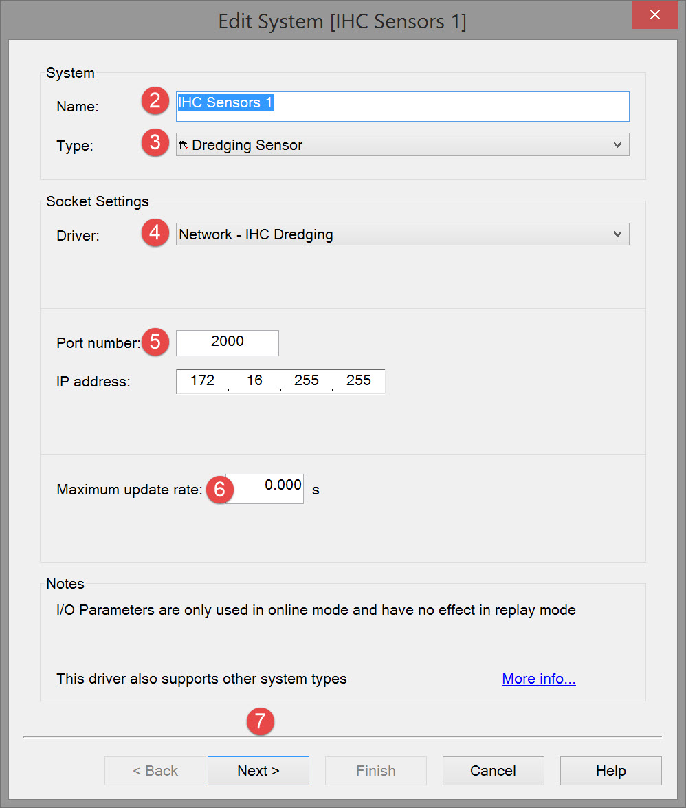


If there is no existing driver, this could also be a driver created with the IO Editor
Note that the interfacing can be either serial or network so make sure to select the correct type.

Please refer to A Note on Interfacing Parameters.

|
Updates |
|
|---|---|
|
Maximum update rate |
Enter a value to determine how often data will be decoded by the interface driver. Some equipment is capable of outputting data at high output rates, but it may not be necessary to use each update.
|
|
Latency |
Latency is the time between the actual measurement made in the sensor system and the time the data message arrives at the port. The time in Qinsy will thus be the arrival time corrected with the latency.
|


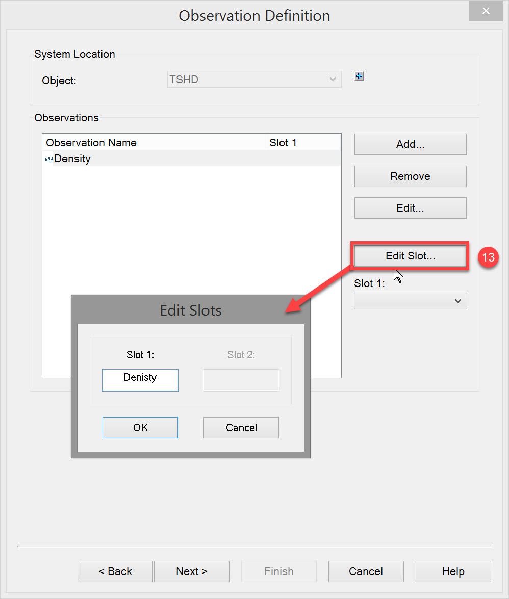

This slot ID must match the identification associated with the parameter in the data message received from the sensor. In this case 'Density' is the identification used in the data message that differentiates the density data field from all other data fields in the message.
Refer to the Drivers & Interfacing Manual for information on fields decoded and slot identifiers to use.
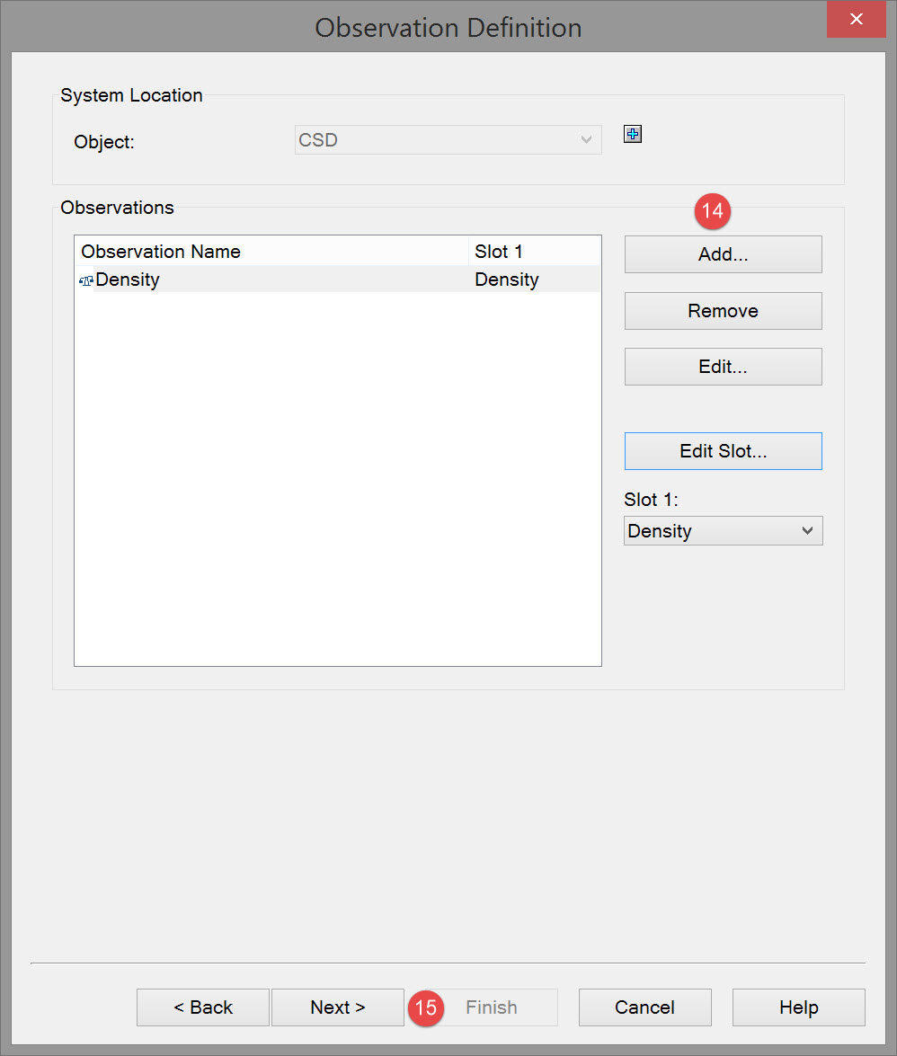

In many cases the data message will not include all of these observations.


|
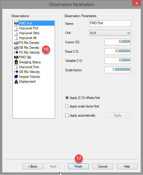
Observation parameters |
|
|---|---|
|
Name |
Enter a descriptive name for the observation. |
|
Unit |
Select the appropriate observation unit. In some cases there will only be one choice. |
|
a-priori SD |
Enter the SD for each observation in turn. |
|
Fixed C-O |
Constant correction to the parameter value. |
|
Variable C-O |
Variable correction to the parameter value. |
|
Scale factor |
Use scale factor to convert the raw output to units in the Acquisition Software.
|

Return to top of page.
Return to: Trailing Suction Hopper Dredger (TSHD) - System Definitions