
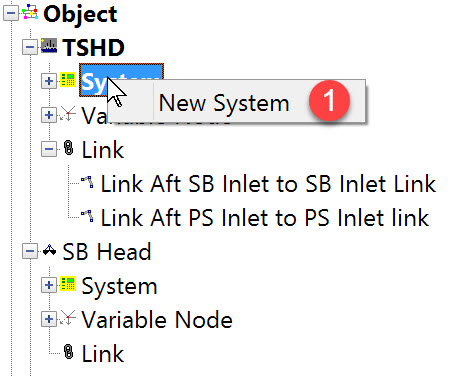
Pseudo-USBL System Definition
Often a dredger's PLC will output the local coordinates of a particular location as dX/dY/dZ 'offsets' from the object reference point. For example the offsets from the vessel's reference point to the center of each drag head.
In QINSy these offsets are interpreted as USBL observations. Hence the name 'pseudo USBL'.

The following dialog opens. It is the first page of a wizard that steps you through the system definition process.
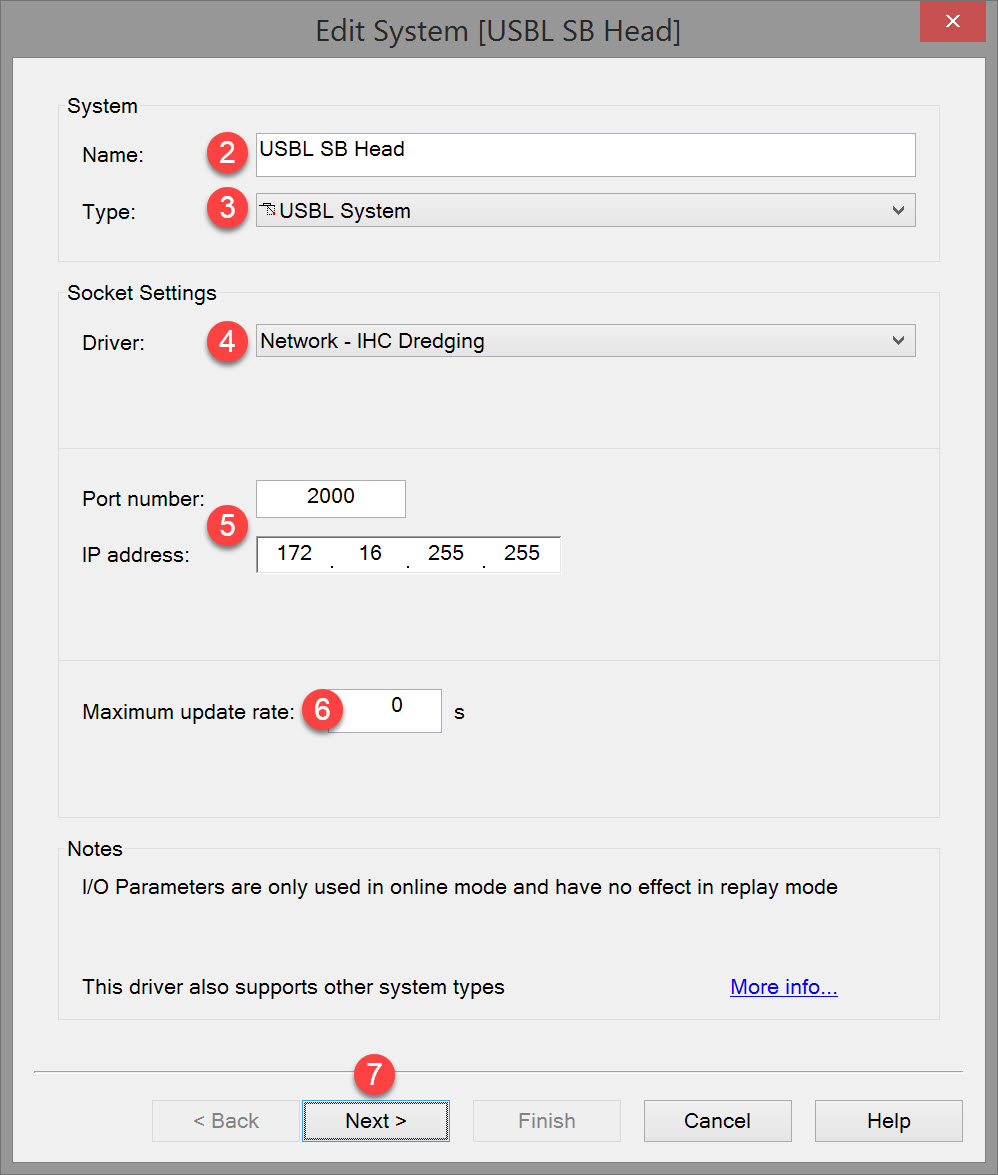


Please refer to A Note on Interfacing Parameters.

Some equipment is capable of outputting data at high output rates, but it may not be necessary to use each update. A position navigation system may for example output values tens of times per second, where five times per second is sufficient. In this case, enter a value of 0.20s. Any data not decoded by the driver is lost and cannot be recovered later.

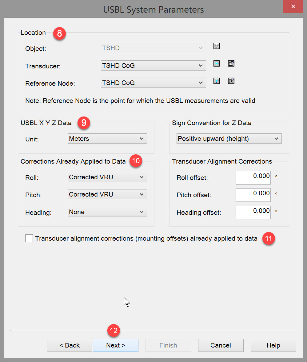

In the case of this pseudo-USBL system it is the reference point from which the dX/dY/dZ values are measured.
|
Location |
|
|---|---|
|
Object |
Select the object on which the pseudo-USBL reference point is located. |
|
Transducer |
Select the position on the object designated as the reference point for the pseudo-USBL measurements.
|
|
Reference Node |
Select the position on the object for which the values output by the pseudo-USBL systems are valid. The Reference Node of an actual USBL system is not necessarily located at the USBL transponder which is why there are two nodes to define.
|


|
USBL X Y Z Data |
|
|---|---|
|
Unit |
Select Survey unit, Meters or International feet as unit for measurements. |
|
Sign convention for Z data |
|
|
Sign convention for Z data |
From the drop down list select either positive downward (depth) or positive upward (height).
|

Also to enter the offset from the transducer to the reference point so that USBL dX/dY/dZ values as output are fully corrected for the attitude of the object and valid for a common point.
Raw corrections from either gyro or MRU are the actual readings made by the gyro and/or MRU.
The corrected readings include any fixed or variable C-O's.
Like an actual USBL system the output from this pseudo-USBL system may or may not have been corrected - check the PLC system.
Here in the system definition you do not choose which gyro or MRU observation to use. With these selections you are only determining whether such observations are to be used in Online computations.
If corrections are not applied in the system itself, it is in the Online Controller under Computation Settings that you select which gyro/MRU observations to use in correcting the pseudo-USBL dX/dY/dZ values for vessel motion.
|
Corrections Already Applied to Data |
|
|---|---|
|
Roll |
Select None if no roll is applied to the USBL data, select Raw VRU when roll is already applied to the data and select Corrected VRU when roll and (fixed or variable) C-O are already applied to the data. |
|
Pitch |
Select None if no pitch is applied to the USBL data, select Raw VRU when pitch is already applied to the data and select Corrected VRU when pitch and (fixed or variable) C-O are already applied to the data. |
|
Heading |
Select None if no heading is applied to the USBL data, select Raw VRU when heading is already applied to the data and select Corrected VRU when heading and (fixed or variable) C-O are already applied to the data. |

An actual USBL system is normally calibrated at sea and Rx (Pitch), Ry (Roll), Rz (Horizontal Alignment) alignment corrections computed. These can be entered in the USBL system itself or in the software.
These corrections are not normally applicable to a pseudo-USBL system.


|
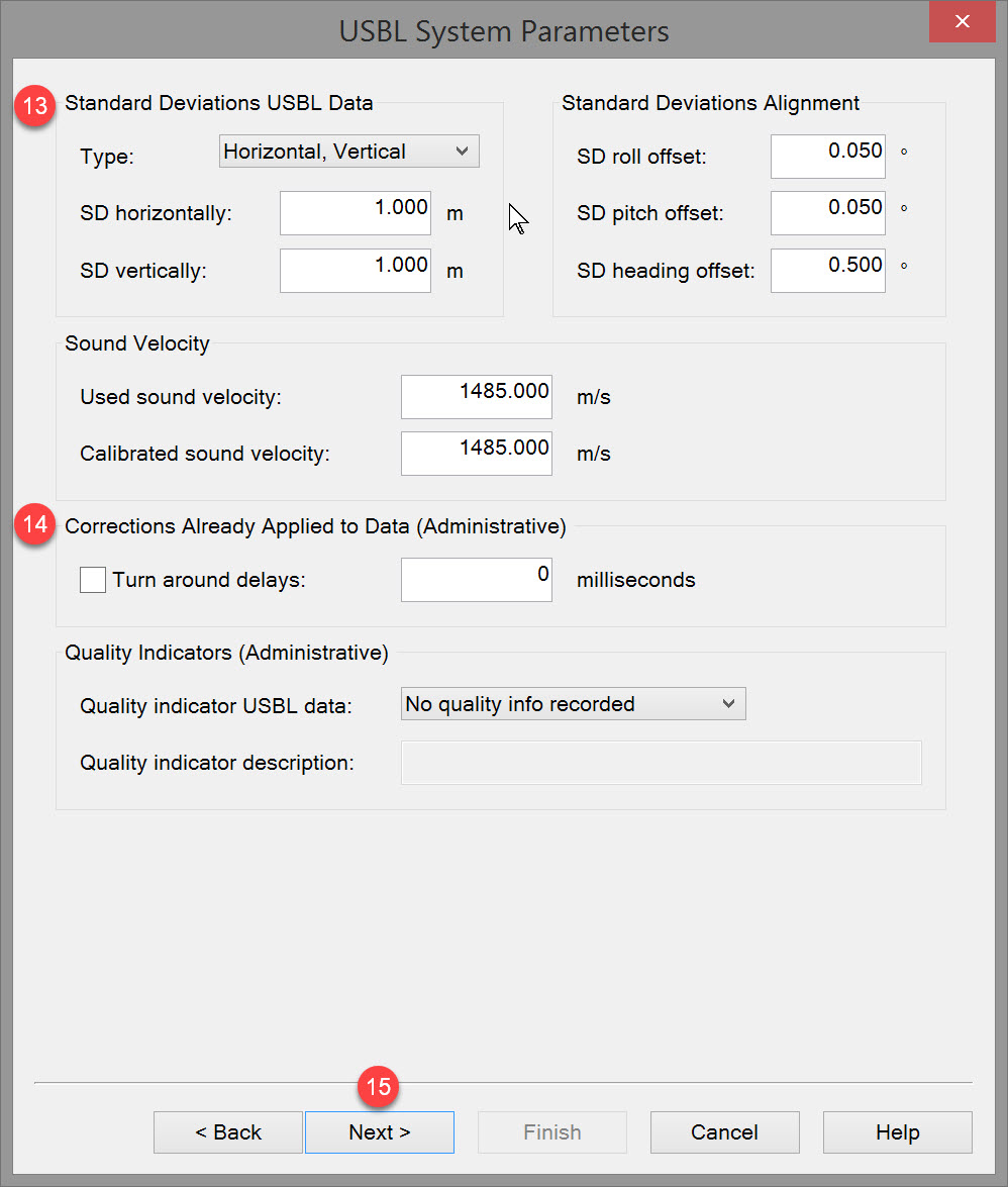
Standard Deviations USBL Data |
|
|---|---|
|
Type |
Type of measurements from USBL: Select "Horizontal, Vertical" (rectangular) or "Angle, Range" (polar).
|
|
SD horizontally / SD angle |
a-priori SD is an indication of the expected variation in a measurement.
|
|
SD vertically / SD range |
Using the same theory as for the horizontal components, estimate the SD of dY. |
|
Standard Deviations Alignment |
A-priori SD values for the installation of the USBL transponder |
|
SD roll offset |
SD value for roll angle relative to ship's coordinate system. Usually not applicable to pseudo-USBL systems. |
|
SD pitch offset |
SD value for pitch angle relative to ship's coordinate system. Usually not applicable to pseudo-USBL systems. |
|
SD heading offset |
SD value for heading angle relative to ship's coordinate system. Usually not applicable to pseudo-USBL systems. |
|
Sound velocity |
|
|
Used sound velocity |
Enter sound velocity that was set as used in the USBL device. Usually not applicable to pseudo-USBL systems. |
|
Calibrated sound velocity |
Enter sound velocity value that was derived from the USBL calibration routine. Usually not applicable to pseudo-USBL systems. |

|
Corrections Already Applied to Data (Administrative) |
These fields have no effect on the data |
|---|---|
|
Turn around delays |
When selected enter a delay in milliseconds. Not applicable to pseudo-USBL systems. |
|
Quality Indicators (Administrative) |
|
|
Quality indicator USBL data |
Select: "No quality info recorded", "Standard deviation", "Signal noise ratio", "System specific" or "Subjective scale".
|
|
Quality indicator descriptions |
Enter the remarks for these parameters. Only possible when one of the Quality Indicators was selected. |


For example the reference point of the primary vessel is also the reference point for the pseudo-USBL system. A dX/dY/dZ measurement is made FROM this reference point TO the reference point on the drag head(s).
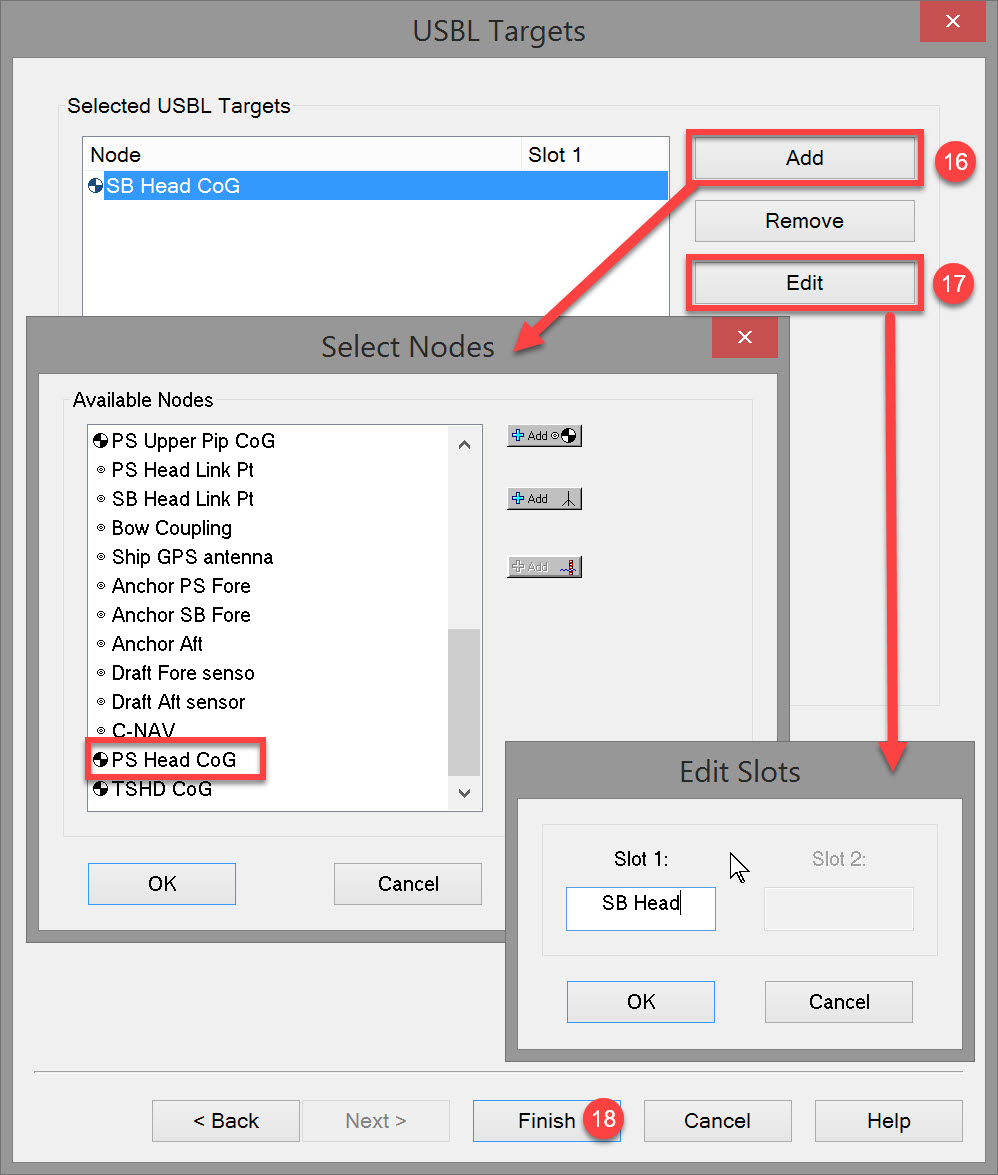
Once targets have been added, this window shows a list of Targets (located on nodes) and Slot identification numbers:
Begin by using the Add button to display a list of available nodes on which the 'target' might be located. The image shows that one node has already been selected as a target so it is not shown in the list. If a second target is required its associated node would be one of those shown listed (e.g PS Head CoG), or, if not listed, a new node can be created.
|
Selected USBL Targets |
|
|---|---|
|
Add |
Opens the Select Node dialog window used to add new nodes.
|
|
Remove |
Select a node in the list and remove this from the USBL system. |


This ID is written into the data message so that when decoding message strings the software can differentiate target 'A' data from target 'B' data.
A pseudo-USBL employs the same concept. If the PLC outputs dX/dY/dZ data from multiple 'targets', each will have a unique identifier. That identifier must be associated with the correct node.
|
Selected USBL Targets |
|
|---|---|
|
Edit |
Once the node has been added click on Edit to open the Edit Slots window.
Not really pertinent to psudo-USBL but something to be aware of: some drivers expect either a "B" or "n", where n is the slot id.
|

Return to top of page.
Return to: Trailing Suction Hopper Dredger (TSHD) - System Definitions