
Pitch Roll Heave Sensor System Definition
Also known as a Motion Reference Unit (MRU), Vertical Reference Unit (VRU) and Motion Sensor.
Make sure you understand exactly what data is being output by the Motion Sensor with regard to the angular measurement and rotation convention.
Check whether lever arms are applied in the sensor itself or need to be applied in the software.
A traditional motion sensor outputs pitch roll and heave values valid only for its location on the object. True values are obtained directly only if the motion sensor is mounted at the center of gravity (rotation point of the vessel). When not located at the vessel's true center of gravity (CoG), the unit does not output true values unless compensation has been made for 'lever arms', i.e. the X/Y/Z offsets of the unit from the CoG.
The choice of vessel reference point (offsets of X=0, Y=0, Z=0) should be as close as possible to the theoretical CoG/turning point of the object. That way lever arm corrections reduce motion sensor raw values to what they would have been if the motion sensor was physically located at the CoG.
If lever arm correction cannot / has not been done in the unit, then it must be done in the acquisition software.
In dredging, motion sensors sometimes measure only pitch, or pitch and roll with no heave.

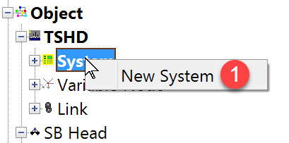
The following dialog opens. It is the first page of a wizard that steps you through the system definition process.
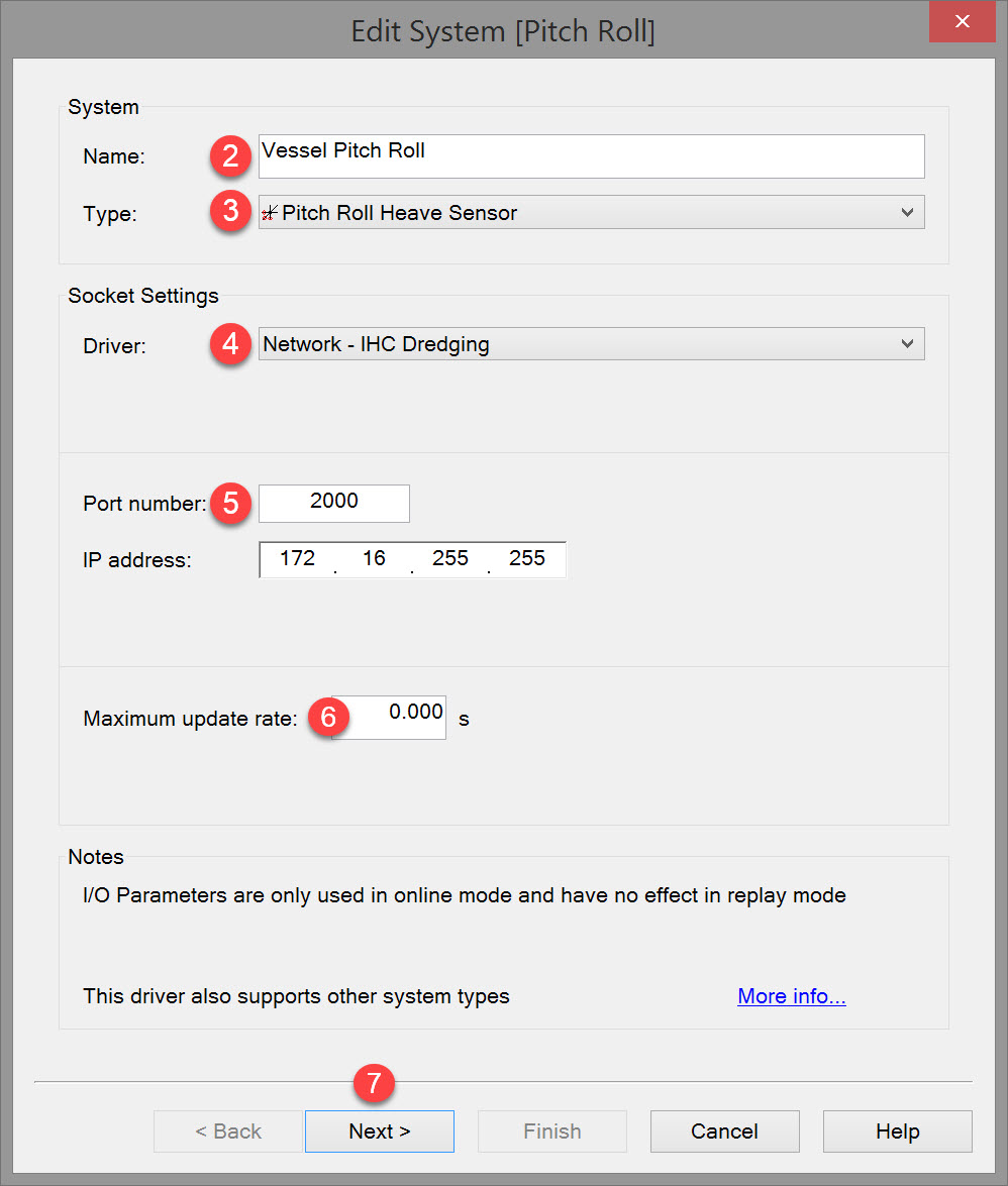


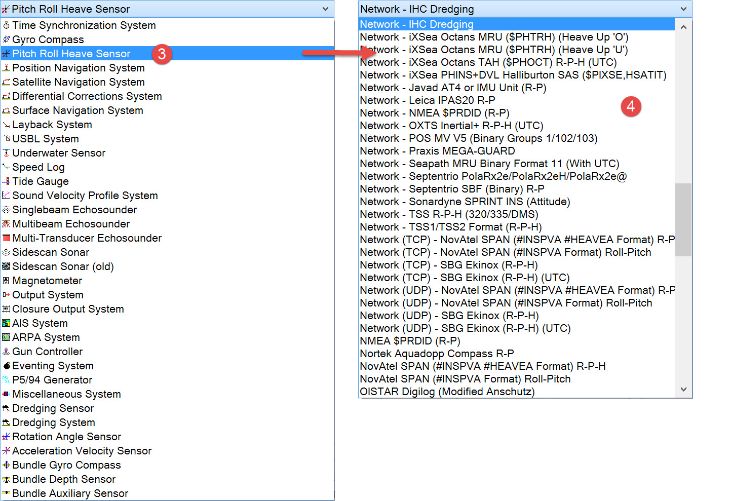

The driver list includes both serial and network drivers. If you have already defined other systems and some of the data messages are sent by the dredger's PLC, it is likely that motion sensor data will also be issued by the PLC.
Note that some drivers only decode pitch, and others only pitch and roll.

Please refer to A Note on Interfacing Parameters.

|
Updates |
|
|---|---|
|
Maximum update rate |
Enter a value to determine how often data will be decoded by the interface driver. Some equipment is capable of outputting data at high output rates, but it may not be necessary to use each update. A motion sensor system may for example output values hundreds of times per second, where twenty times per second is sufficient. In this case, enter a value of 0.05s. Any data not decoded by the driver is lost and cannot be recovered later. |
|
Latency |
Latency is the time between the actual measurement made in the motion sensor system and the time the data message arrives at the port. The time in QINSy will thus be the arrival time corrected with the latency.
|

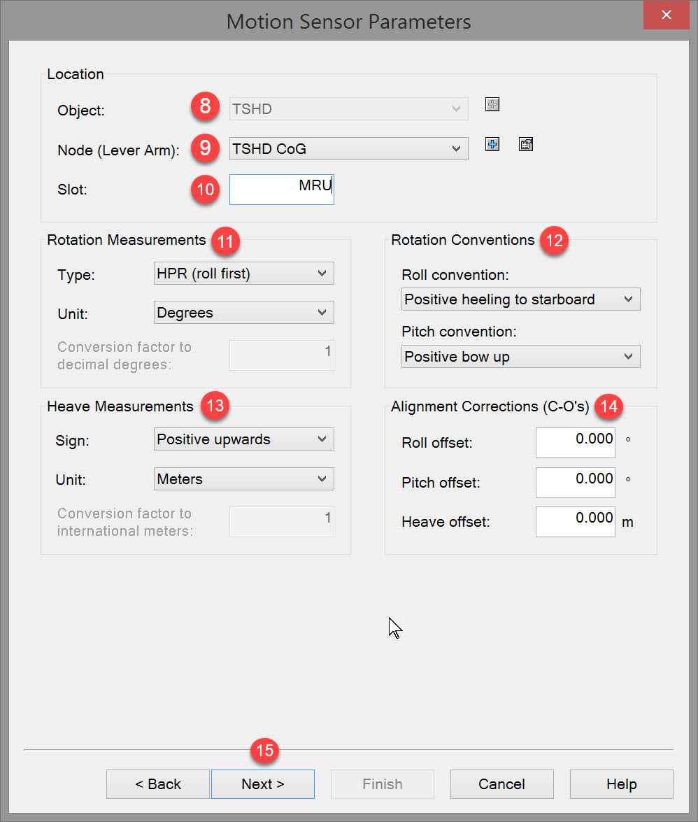


If the current drop down list does not include the motion sensor location click the "New Node" 
We advise to always define this node, as it may come in handy when Replaying data at a later stage.

The slot number is used by the driver to decode the correct data field. Hence the value entered here must correspond exactly to the identifier contained in the data message. In the example, the identifier in the data message is MRU and so becomes the slot number entered here.

The settings refer to the order in which roll and pitch are measured inside the motion sensor itself (see Note below). Most of the commonly used sensors measure heave, pitch and roll in that order but double check by referring to the sensor documentation.
The capital letters in each option refer to the order in which the parameters are measured in the sensor itself.
If roll is measured last in the sensor (HPR), QINSy will apply it first in the rotation matrix it uses in computations, otherwise you will get errors.
Hence the reference in the brackets – HPR (roll first).
So the capital letters in each of the 4 options refer to the order in which the parameters are measured in the sensor itself, and the words following in brackets refer to the order in which QINSy will apply the parameters.
For almost all motion sensors you would select “HPR (roll first)”. Please check your motion sensor manual if in doubt.
Measured parameters vs Output parameters
The order in which the parameters are output by the sensor in the data string is not necessarily the order in which the parameters are measured in the sensor itself.
That is why this is also a setting in QINSy. The QINSy driver decodes the motion parameters in the order they are parsed in the data string. But the same data string may be output by another motion sensor which measures the motion parameters in a different order.
The good news is that in QINSy, if you select the wrong option here, you can replay the raw data DB file with a different option and generate new results.
|
Rotation Measurements |
|
|---|---|
|
Type |
Select whether to apply roll first or pitch first in the rotation matrix QINSy uses in computations. |
|
Unit |
Select Degrees, Grads or Other. If Other is selected, then enter a value for conversion factor to decimal degrees. |

Better still: perform a small check by tilting the unit in the roll and pitch directions, or wait for the object to move and check the sign of the observation that is output (using the Generics Display or Timeplot Display).
|
Rotation Conventions |
|
|---|---|
|
Roll convention |
Select positive heeling to starboard or positive heeling to port. |
|
Pitch convention |
Select positive bow up or positive bow down. |

Check the sensor manual and/or check the sign of the observation that is output as the moves up and down (using the Generics Display or Timeplot Display).
|
Heave Measurements |
|
|---|---|
|
Sign |
Select positive upwards or positive downwards. |
|
Unit |
Select Meters, International Feet or Other. If Other is selected, then enter a value for conversion factor to International Meters. |

In a perfect world the two reference frames are exactly parallel in all three planes. In practice, these reference frames are rarely absolutely aligned. Misalignment affects motion measurements and must be corrected for. The well-known patch-test does not yield the angular offsets between the motion sensor and the Object’s reference frame (ORF). In addition to this, any misalignment between the vertical rotation axis of the motion sensor and the ORF (yaw-angle) introduces cross-talk between pitch and roll. How these angular offsets are calibrated is beyond the scope of these help pages. A good explanation is provided in the November 2008, Volume 12, No.9 issue of the Hydro International magazine
As with lever arms, the motion sensor alignment corrections can be entered either in the sensor unit itself or in QINSy. If the Motion Sensor unit has NOT been set up to reduce for heave, pitch and roll corrections (C-O) these corrections should be entered here.
C-O corrections are always added to the raw observation, hence if your motion sensor reads +3 degrees (typically bow up) and you want it to read zero, enter a correction value of -3 degrees.
Pitch and Roll correction values must be in angular measurement units, whilst a Heave correction is expected to be in meters.
|
Alignment Corrections (C-O's) |
|
|---|---|
|
Roll offset |
Enter roll C-O in degrees or selected unit. |
|
Pitch offset |
Enter pitch C-O in degrees or selected unit. |
|
Heave offset |
Enter heave C-O in meters or selected unit. |

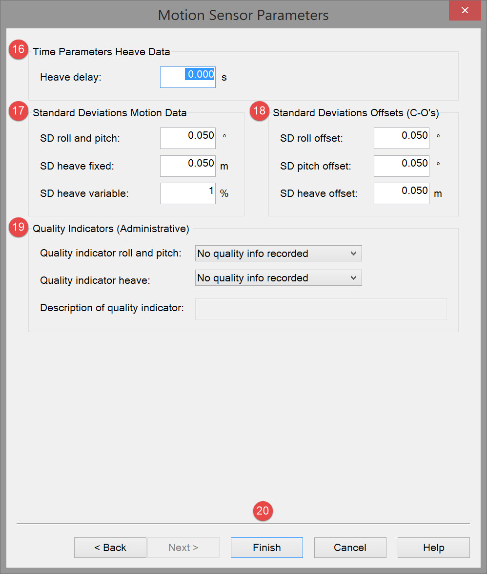

|
Time Parameters Heave Data |
|
|---|---|
|
Heave delay |
Any time delays of the motion sensor data from their time of validity to the time when the data is available at the interface port must be determined.
|

|
Standard Deviations Motion Data |
|
|---|---|
|
SD roll and pitch |
A-priori SD for pitch and roll. See manufacturer's manual for these values. |
|
SD heave fixed |
A-priori SD for heave. See manufacturer's manual for these values. |
|
SD heave variable |
Variable component of heave SD. See manufacturer's manual for these values. |

|
Standard Deviations Offsets (C-O's) |
|
|---|---|
|
SD roll offset |
A-priori SD for roll offset. See installation report for these values. |
|
SD pitch offset |
A-priori SD for pitch offset. See installation report for these values. |
|
SD heave offset |
A-priori SD for heave offset. See installation report for these values. |

|
Quality Indicators (Administrative) |
These fields have no effect on the data |
|---|---|
|
QI indicator roll and pitch |
Select: "No quality info recorded", "Standard deviation", "Signal/noise ratio", "System specific" or "Subjective scale". |
|
QI indicator heave |
Select: "No quality info recorded", "Standard deviation", "Signal/noise ratio", "System specific" or "Subjective scale". |
|
Description of quality indicator |
Enter remarks for these parameters. Only possible when one of the Quality Indicators was selected. |

Return to top of page.
Return to: Trailing Suction Hopper Dredger (TSHD) - System Definitions