
It assumes you have already created a template database and defined the survey geodetics.
On this page:
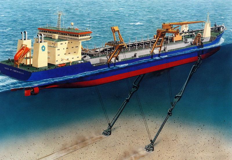
TSHD Object Definitions
Vessel (dredger) definition

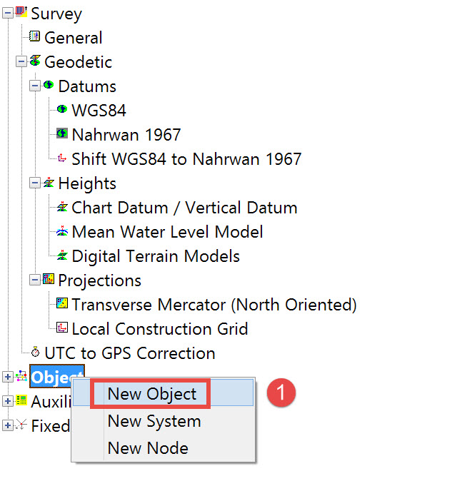
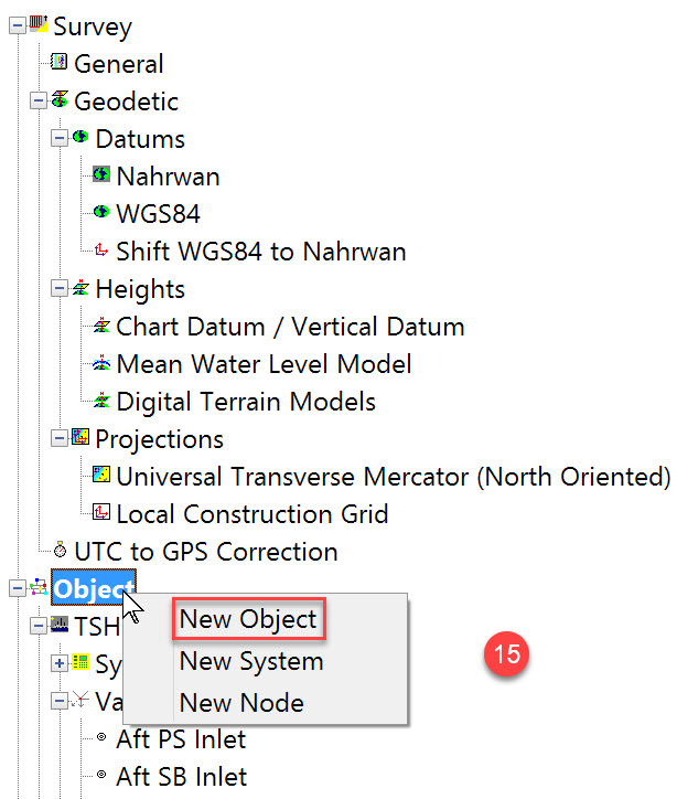
or by right clicking on the tree item 'Object' and selecting 'New Object'.
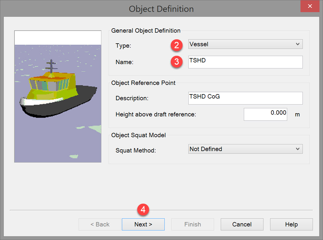
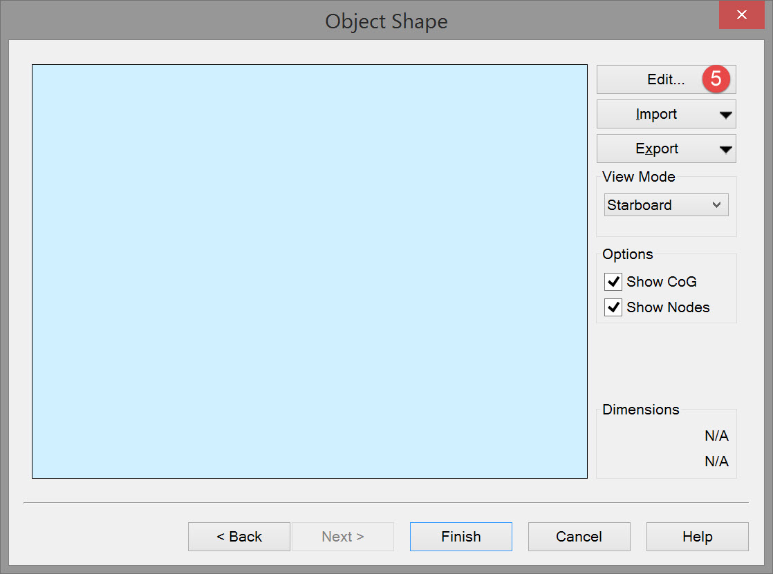
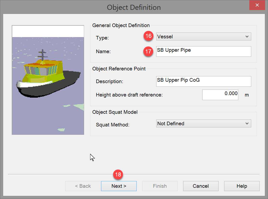
The following dialog appears:


The following dialog pops up:
Use the 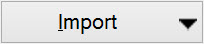
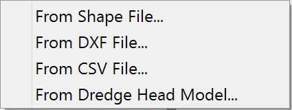
Note that 'Shape' file refers to the file that is made in QINSy when a vessel shape is exported.
Clicking on 'Generate' creates a simple vessel shape, not normally suitable for dredging purposes.
Please refer to Database Setup Help pages for assistance in importing existing vessel shapes.


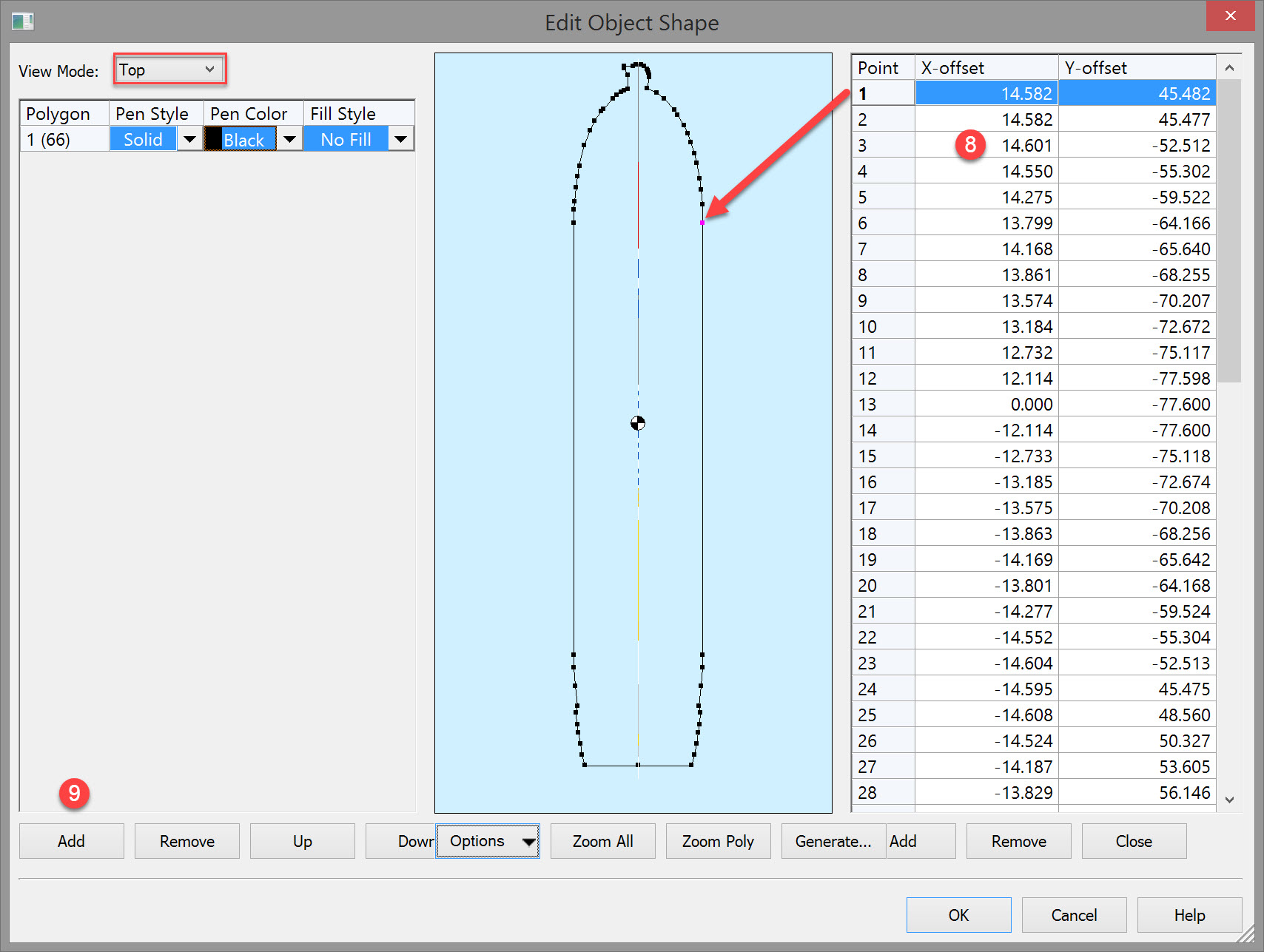

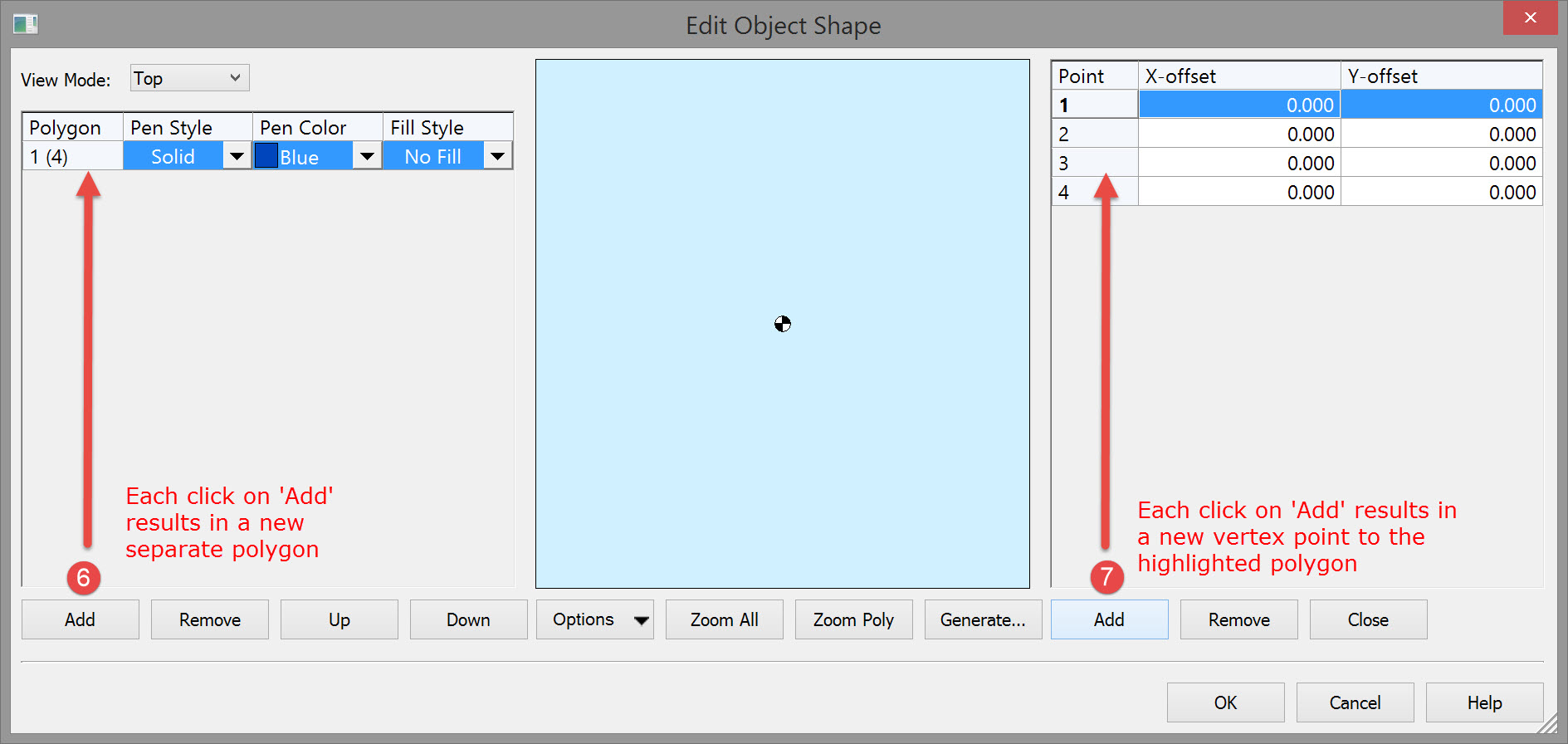
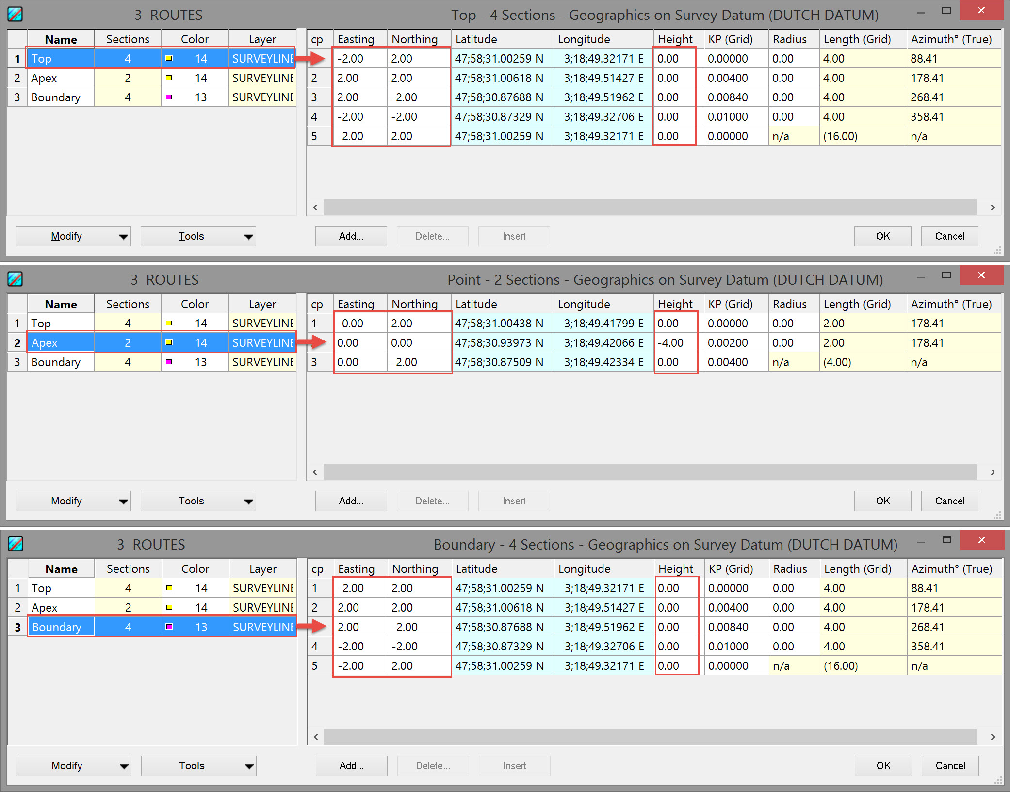
A local XYZ coordinate system is used based on the vessel reference point. Define shape, color and fill.
When creating polygons start with one point and then add points in a sequence proceeding around the perimeter in one direction only, i.e. clockwise or anti-clockwise.
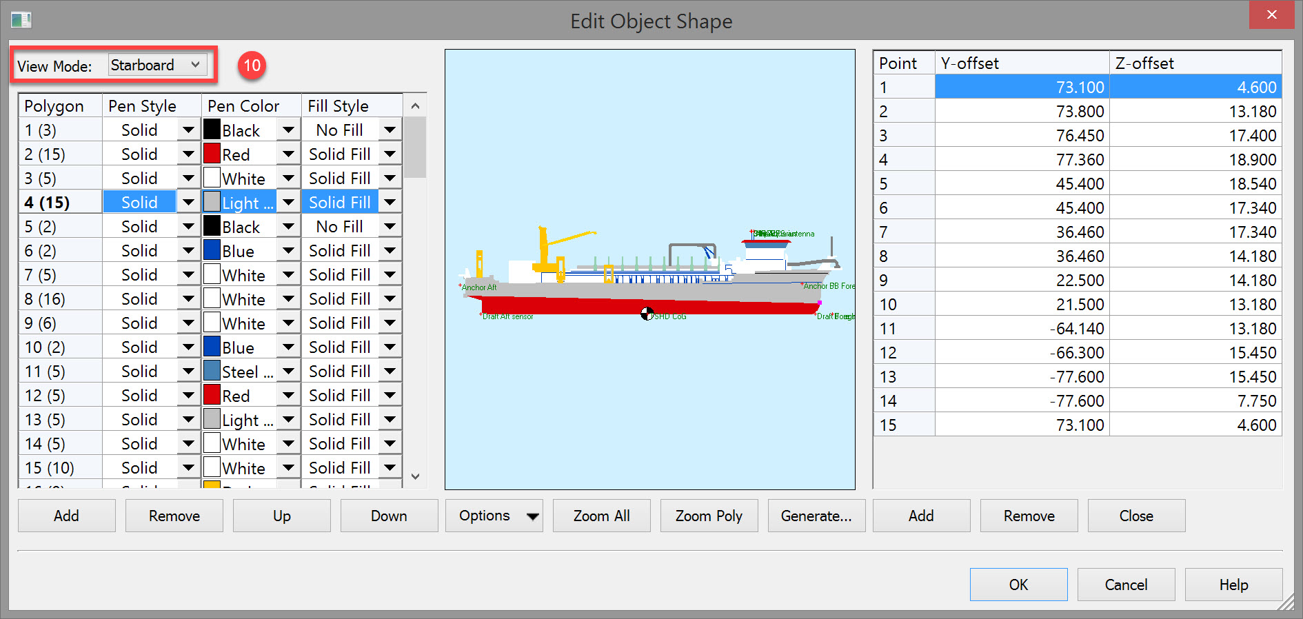
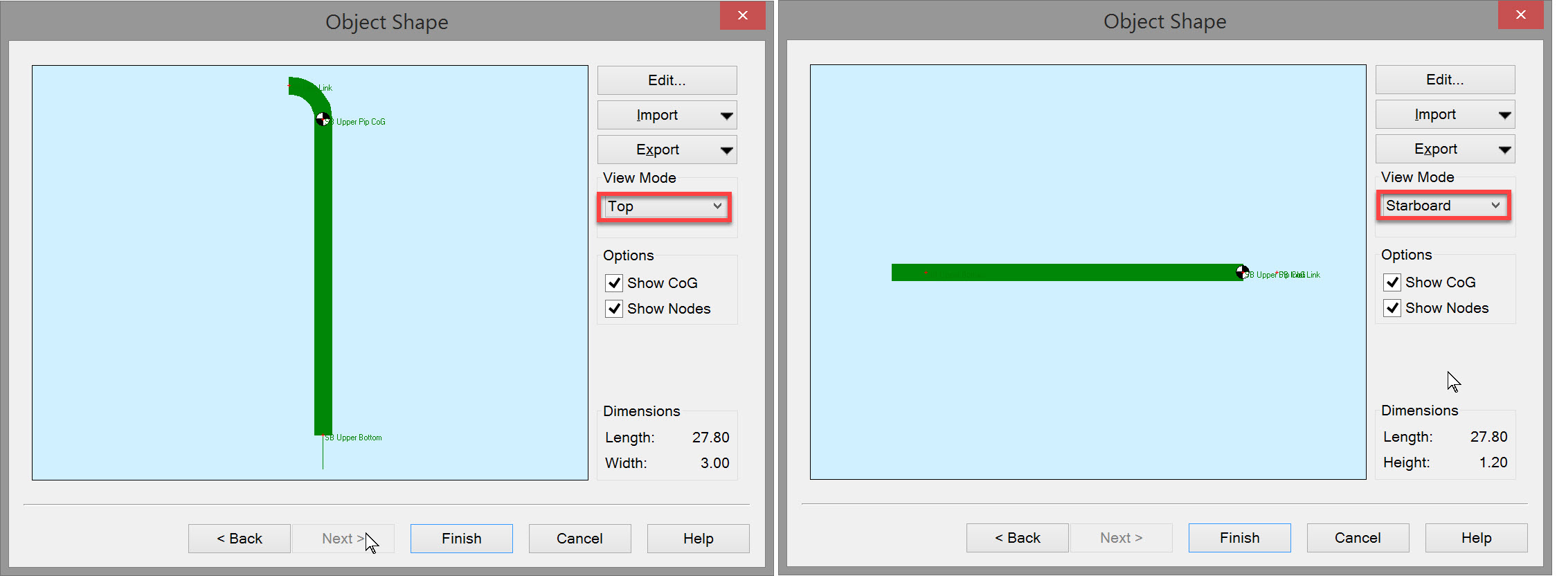
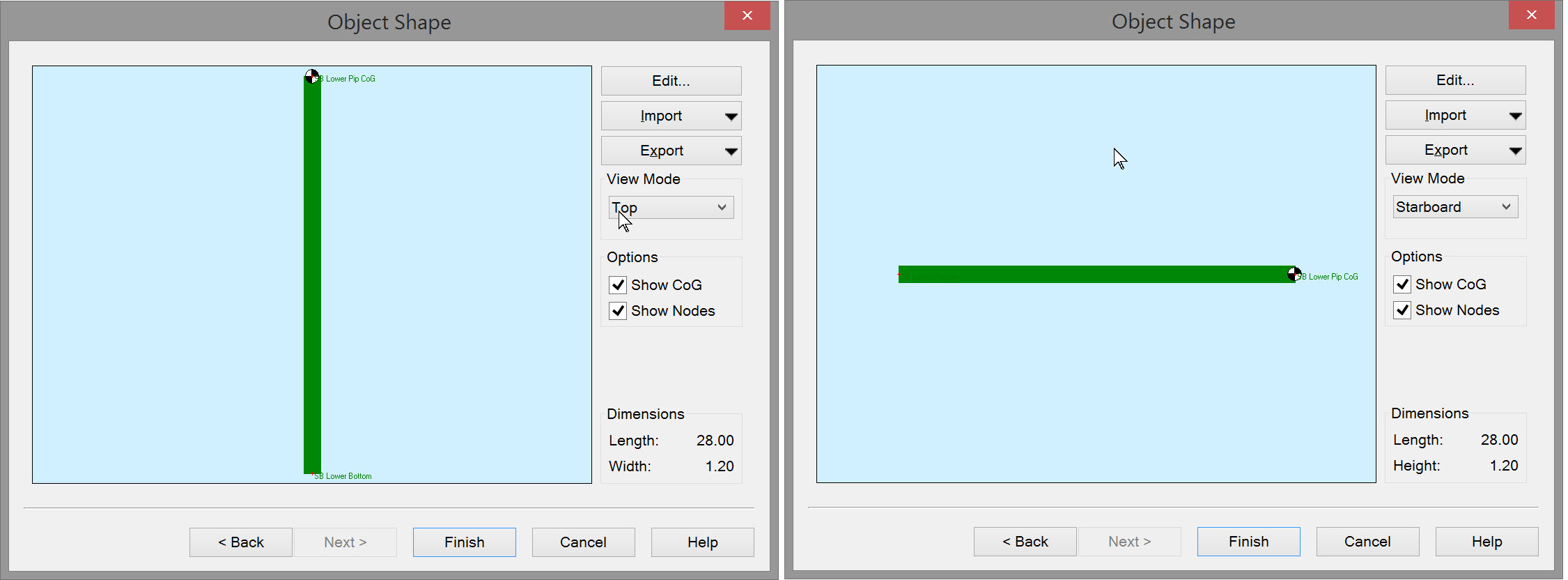
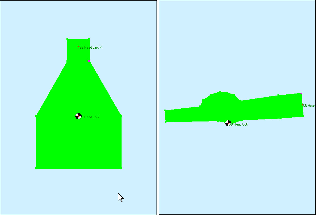
Note that a 'Top View' is being created. You can also add profile views from starboard and aft.

The following dialog shows a complete top view.
-
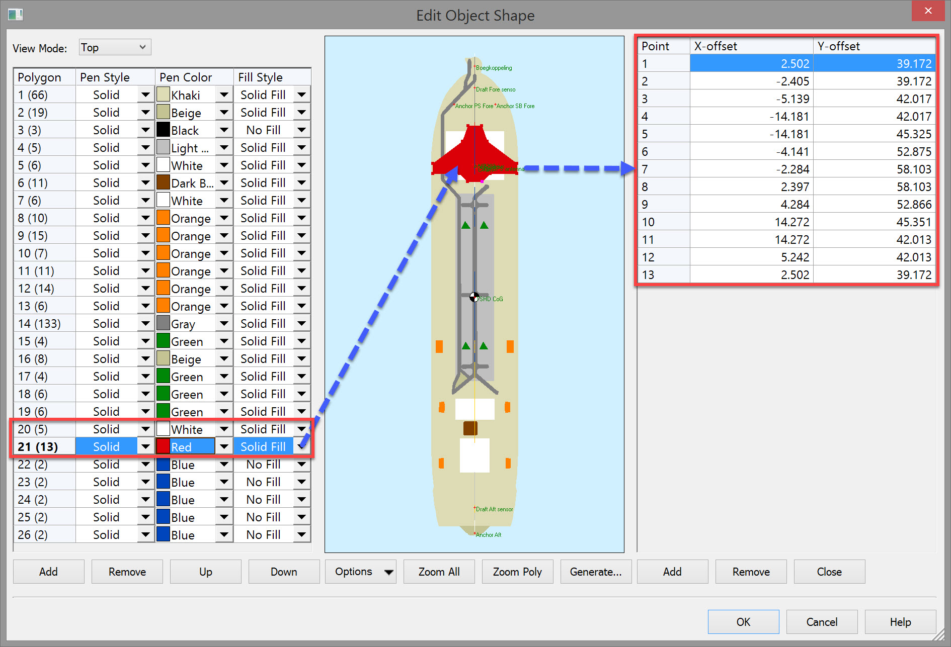
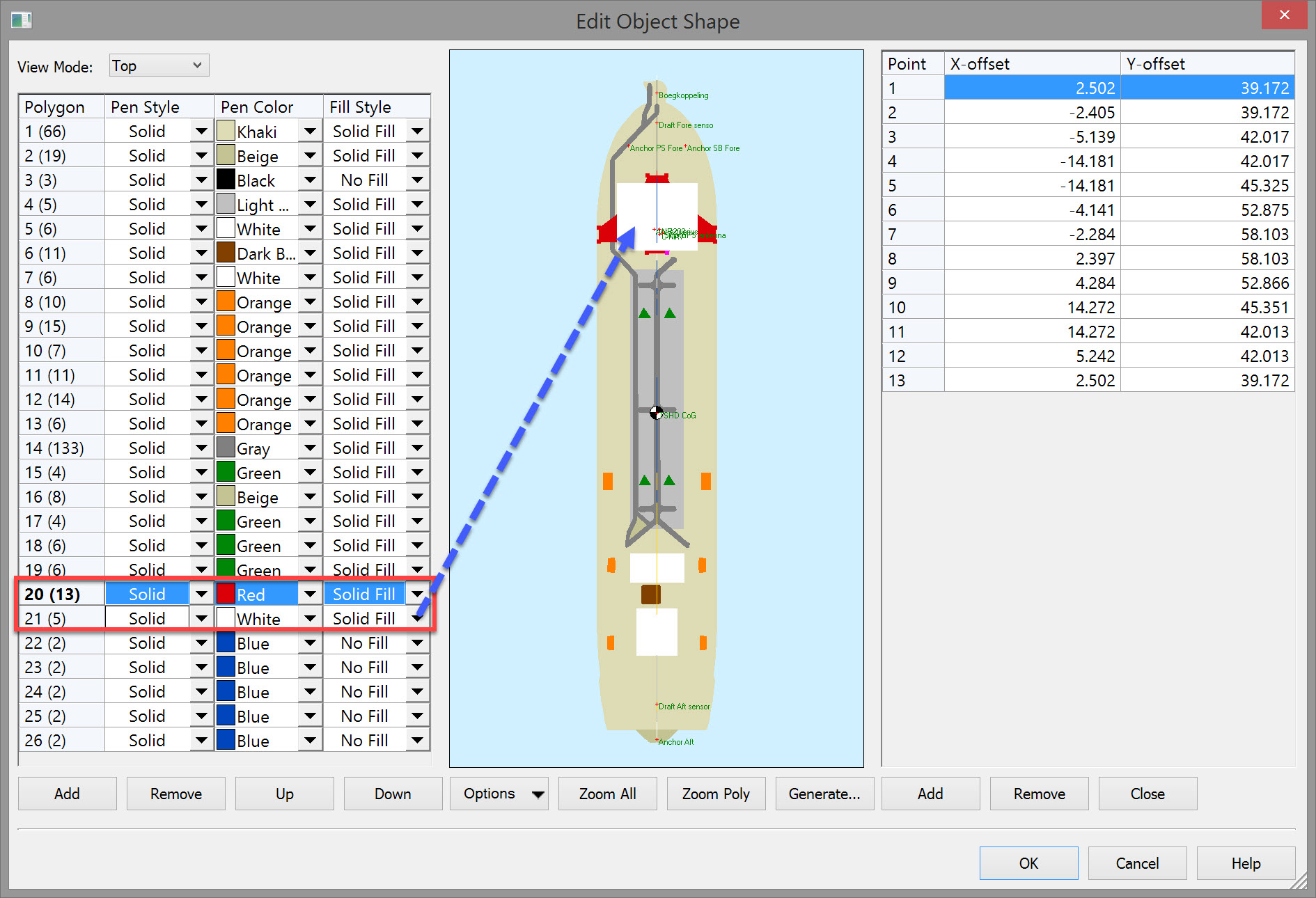
If one shape lies inside the perimeter of a second shape, alter the order of the polygons listed on the left. For example, in the picture above, polygon #21 (red fill) lies partially within polygon #20 (white fill). If the order were reversed all of the red filled polygon would not be visible (see below). Polygon #1 is the base; any additional polygons fall on top of polygon #1.
-
Highlighting a polygon on the left results in its vertices being shown on the right.
-
The vertex highlighted on the right is colored magenta in the graphic pane.


-
1000 vertices are available, shared between top, starboard and aft views.
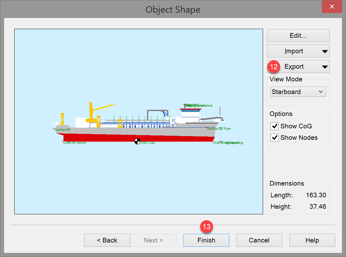
Click OK to finish and return to the Object Shape dialog.


-
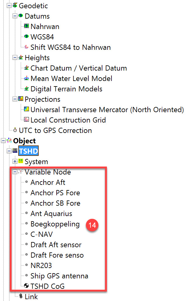
the position of each system sensor (e.g. GNSS antennas), position of winches and/or fairleads, and inlets.
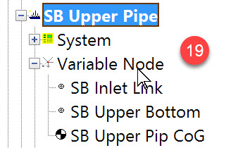
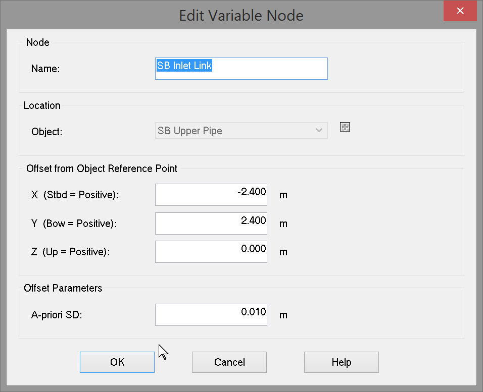
To add nodes right click on the tree item 'Variable Node' and select New Node to create another node, e.g.
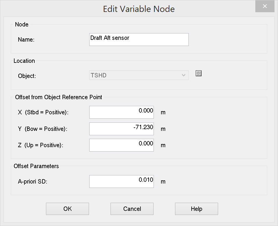
Enter a node name, the object on which the node is located and the offset values FROM the object reference point TO the new node location.
Return to top of page.
Trailing Suction Arm Definition
Upper Pipe
In order to visualize the suction pipes moving relative to the dredger, define a 'pipe' object.

This opens the Object Definition wizard again. Since this is a second independent object, the initial dialog is empty.


Follow the directions from Step
Your results should look something like this, or be more elaborate:

Right click on the tree item 'Variable Node' and select 'New Node'.
Type in a name, select the object on which the node is located and enter the offsets FROM the object reference point TO the new node location.
Add any other variable nodes that are useful. At a minimum add nodes for:
-
-
the center of the pipe elbow where it connects to the inlet.
-
The center of the other end of the pipe where it connects to the lower suction pipe.
-
When there are two trailing arms, export the shape just defined for the starboard side.
Create a new object for the port side and import the starboard shape.
The elbow points in the opposite direction so change the signs for all the X offset values.
Lower Pipe
Repeat the process to define a shape for the starboard and port lower pipes:
Add a variable node at the lower end of the pipe to use as a connection link to the starboard dredge head.
Return to top of page.
Dredge Head - Wizard Page 1
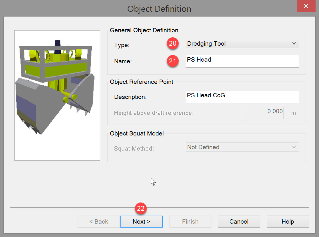
Right click on the tree item 'Object' and select 'New Object'. This opens the Object Definition wizard again. Since this is another independent object, the initial dialog is empty.
Unlike the previous objects all defined as 'vessels', a dredge head is of type 'Dredging Tool'.


Dredge Head - Wizard Page 2
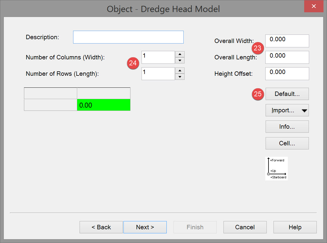
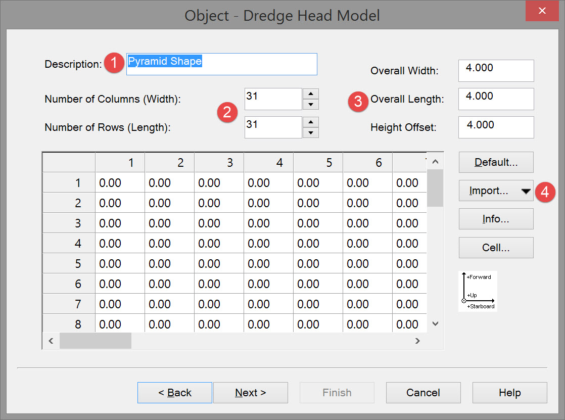
On this page a model of the dredge head can be created. The model is based on a spreadsheet. Overall width and length define the size of the dredgehead, and every cell represents a dredge head height from the base of the head, typically zero.
The number of rows and columns (M, N), cell height and width are user-selectable, M and N must be odd. Cells can also be excluded from the model when footprint is not a square but, for example, oval shaped.
A rectangular grid is defined by:


This results in the creation of an empty spreadsheet. The more columns and rows the more detailed the model will be.
When determining the number of rows and columns of the matrix, take into consideration the required accuracy, sounding grid cell size and available PC power. Every matrix cell will represent a sounding so the more cells, the more CPU load it will take to process the soundings and the higher the accuracy.
However the most important factor is the cell size of the sounding grid you wish to update. If the size is 0.5 by 0.5 units then choose a dredge head model cell size of at least 2 times smaller. This will guarantee that every grid cell is hit by the model’s sounding with every possible dredger heading.
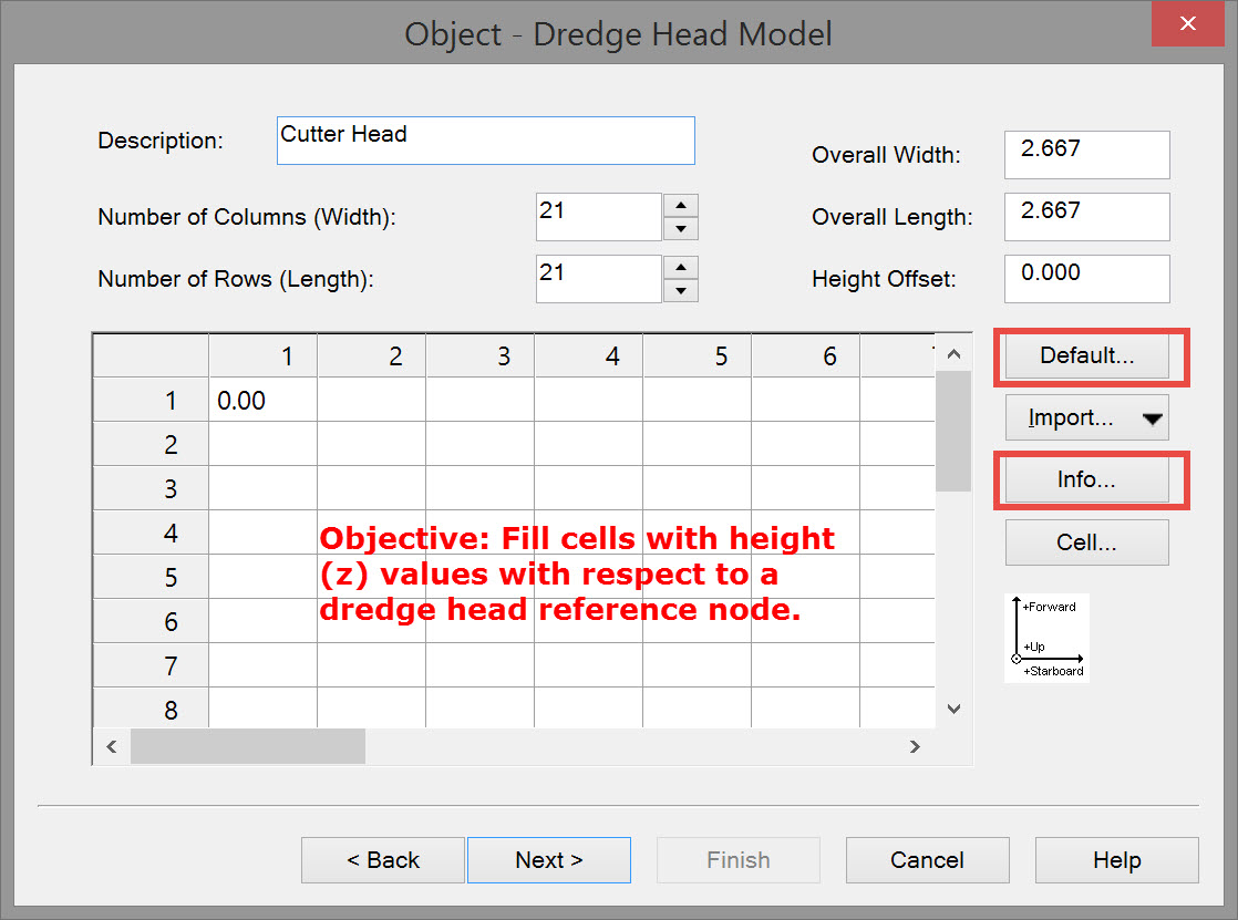
The center cell of the grid becomes the reference point that is linked elsewhere to a defined variable node.
The objective is to enter a height into each cell that represents the distance above (+ve) or below (-ve) the reference point.

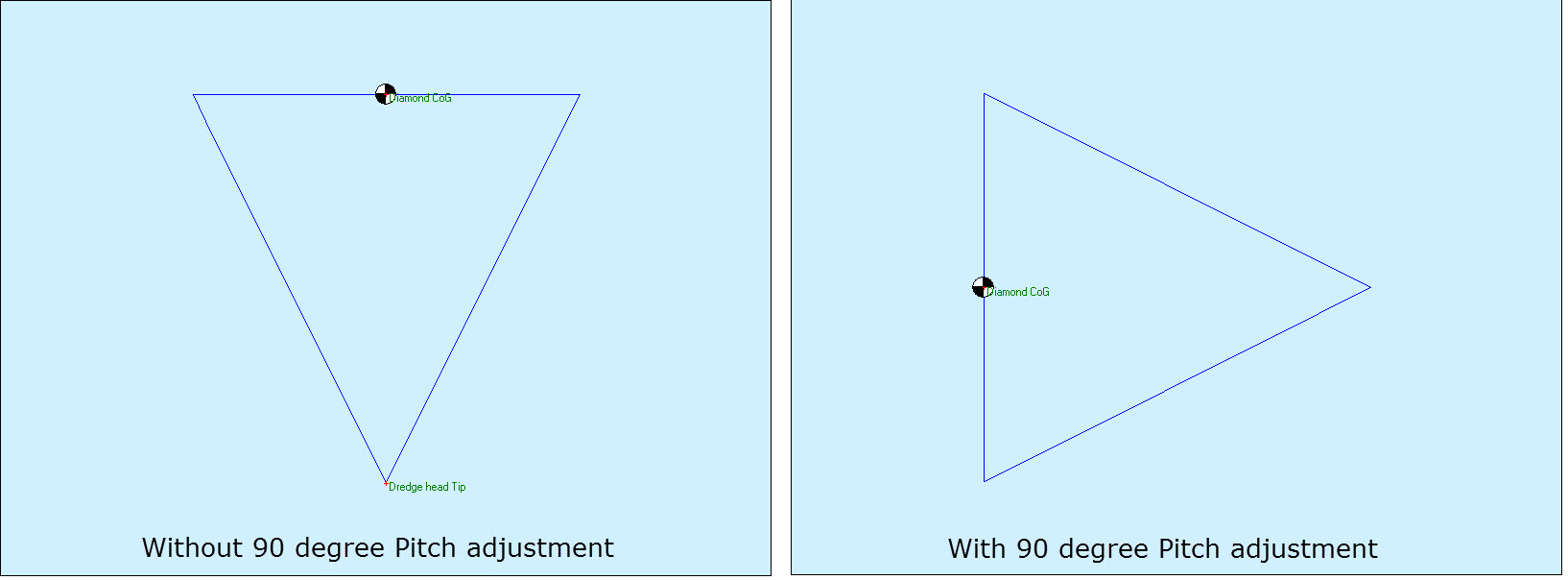
The following dialog pops up:
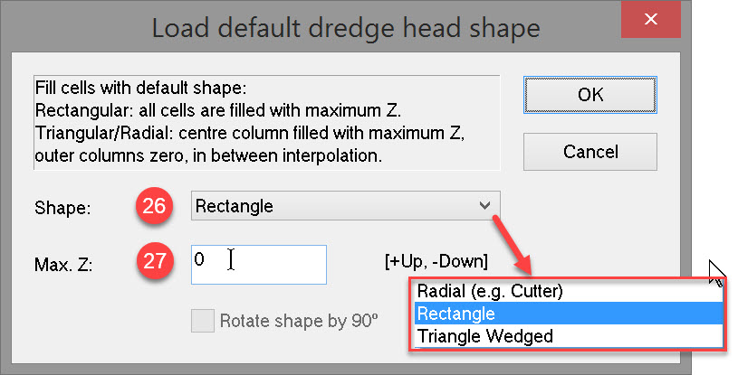


Rotate Shape by 90 degrees is only available for the Triangle Wedged shape to let it face the right direction.
After pressing OK the Object-Dredge Head Model dialog is updated:
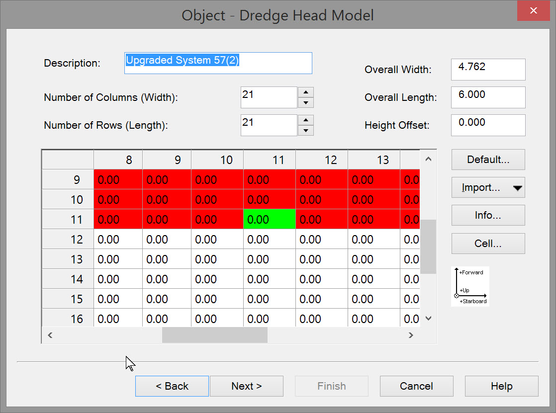
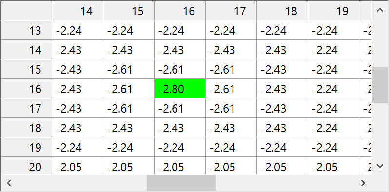
Cells shown in red are disabled, do not have a height value and are not used in the excavated volume computation.
Cells shown in white are enabled. Each has a height value referenced to the reference node of the cutter head. All enabled cells are actively used in the excavated volume computation.
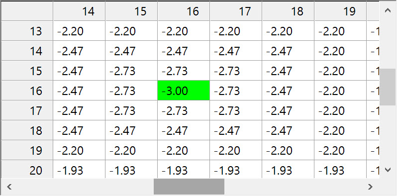
The cell shown in green represents the center of the model.
The following options are available:


Return to top of page.
Dredge Head - Wizard Page 3
Initially the Object Shape dialog is empty.
Click on
to open the Edit Object Shape dialog.
Follow the same procedure described above to define the dredge head shape in top, starboard and aft views.
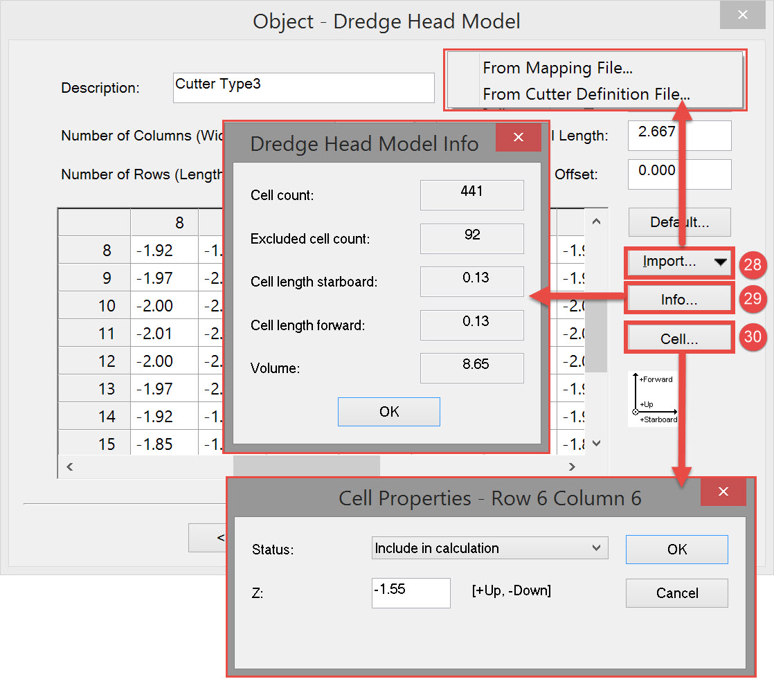
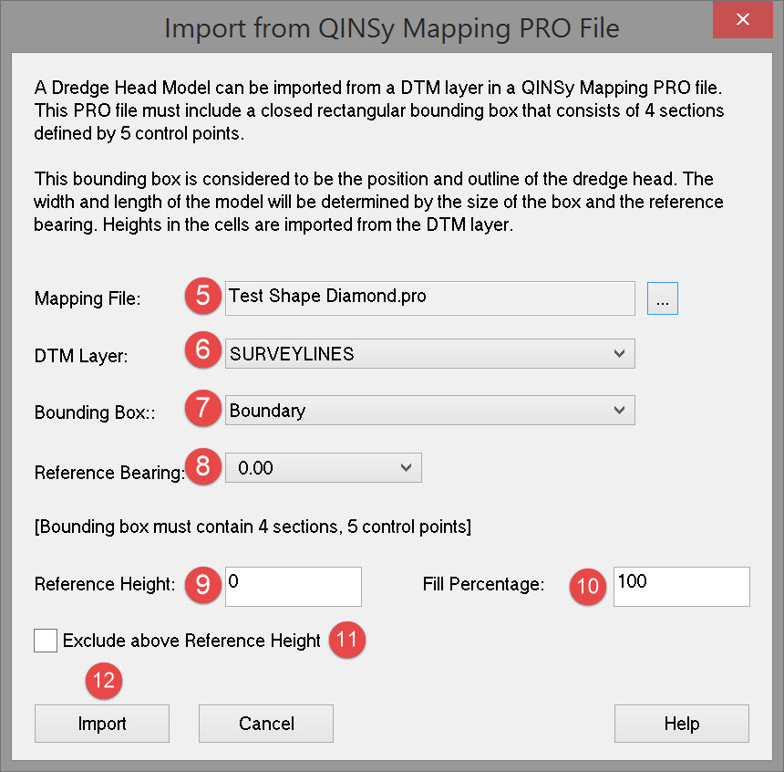
Importing Dredge Head Model
From Mapping File
Using the Line Database Manager ![]()
These numbers create a shape like this:
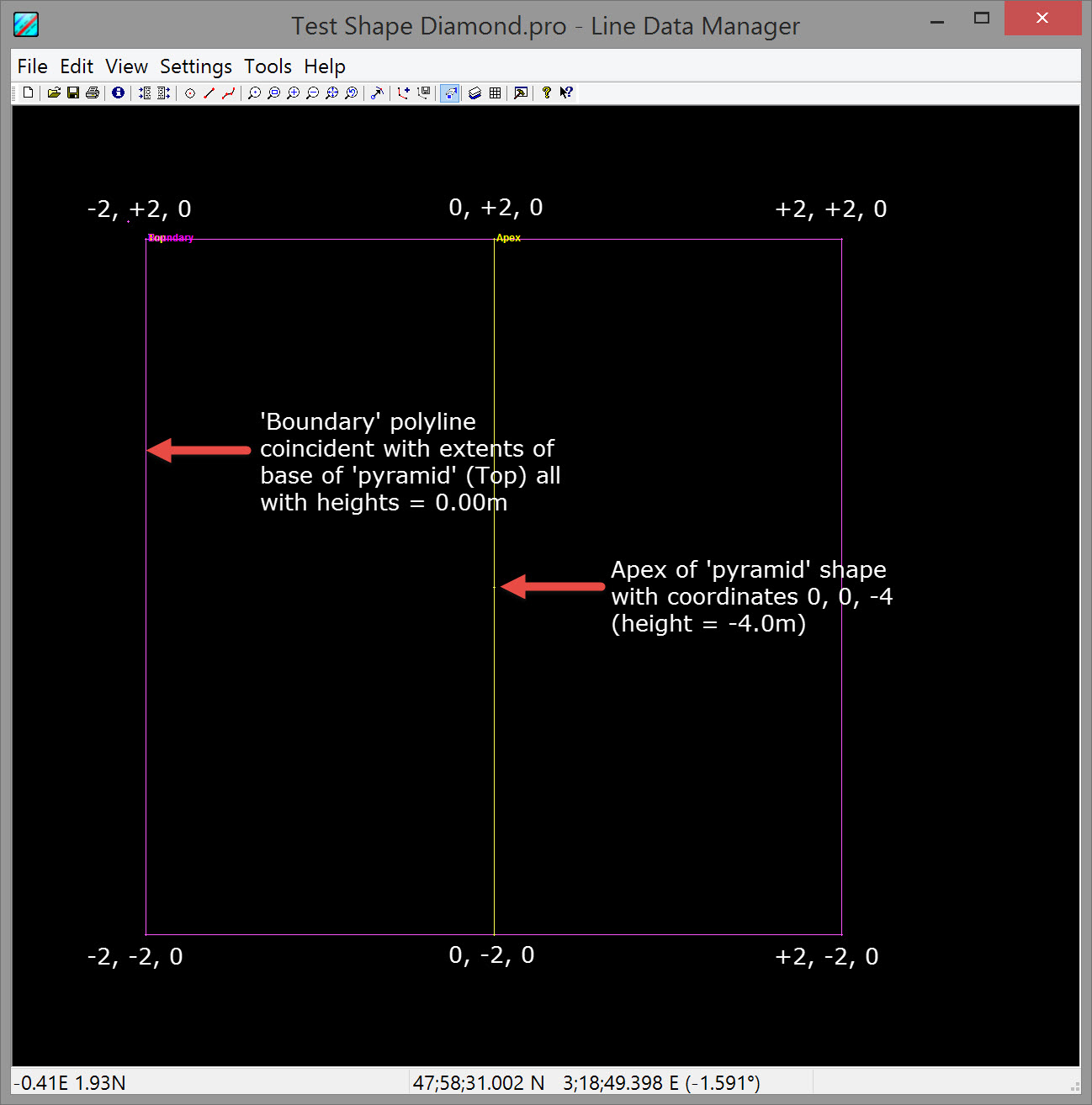
When defining the Dredging Tool object, import this PRO file as follows:


Remember the more cells defined the more accurate is the updating of the sounding grid but at the expense of CPU power.

These numbers divided by the number of rows and columns determines the cell size.


This line can share the same extents as the design model or can be a little larger.


In our example the height is -4.00m. Setting the Reference Height to -1.00m yields this result for the height at the reference point of the model:

For example, entering 70% yields the following result for the height at the model reference point:

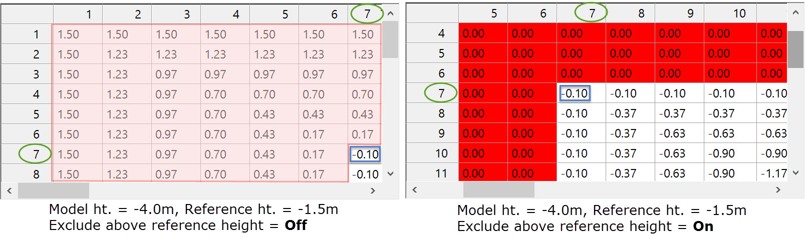
On the left all the values enclosed in the pink area have positive heights and will be used in the computation of volume, which is probably not wanted.
On the right all cells with positive values are disabled.

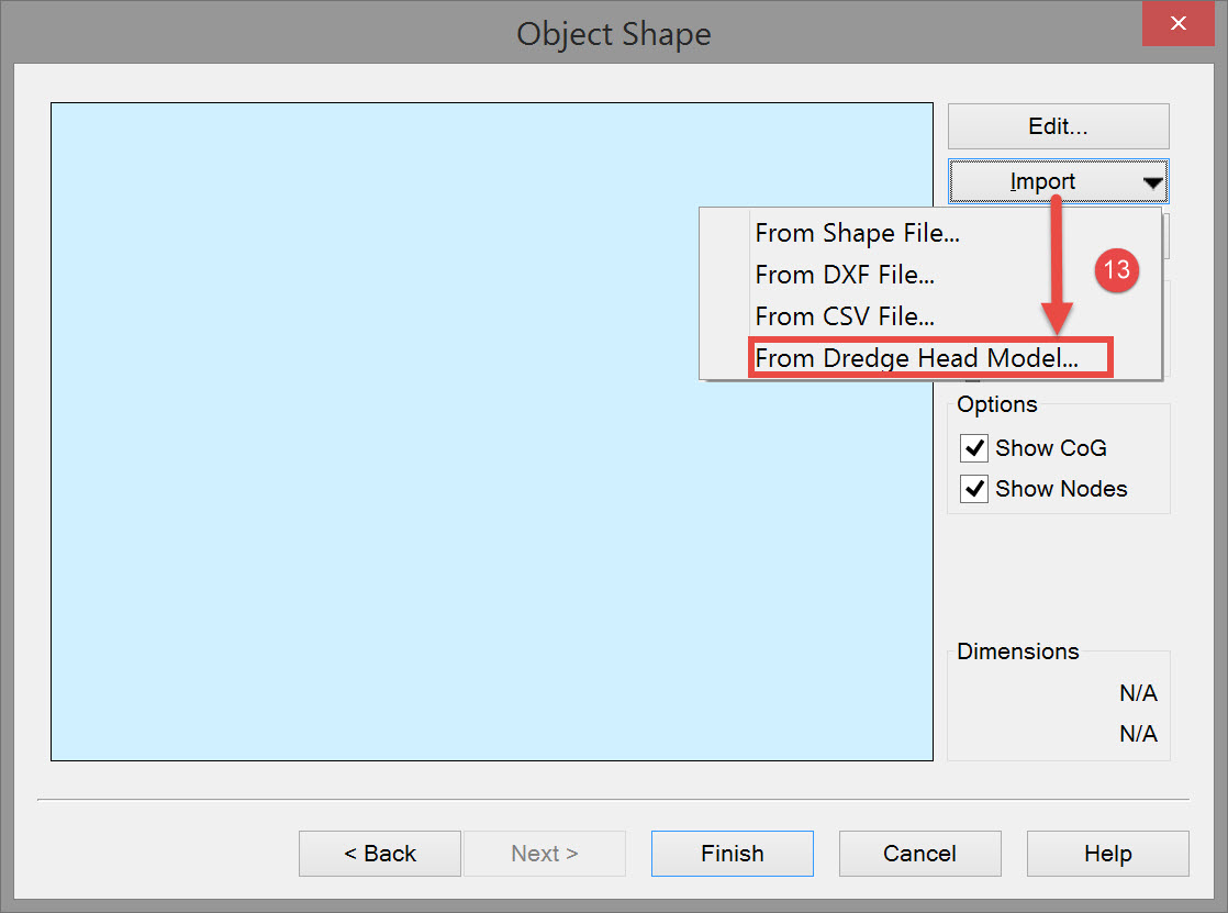

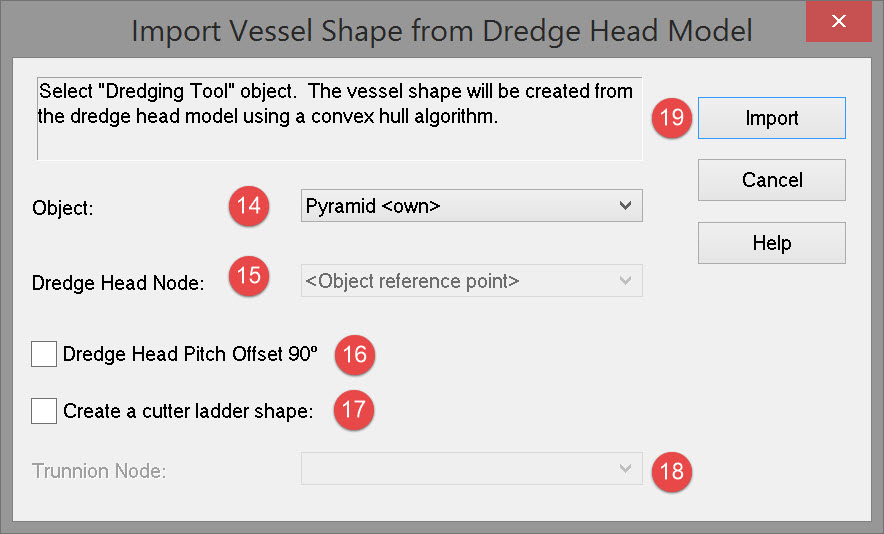
This opens the Import Vessel Shape from Dredge Head Model dialog:


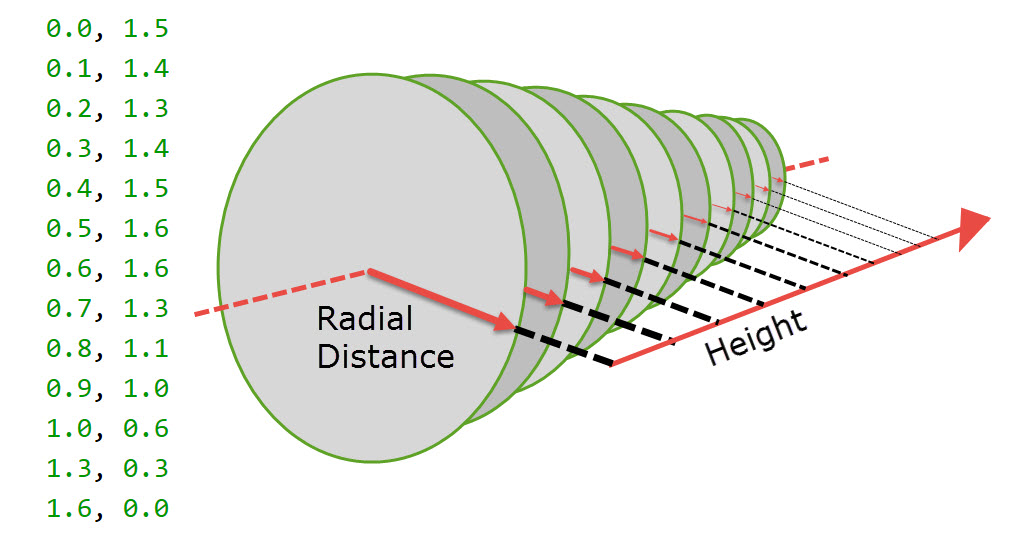
From Cutter Definition File
The cutter definition file is a text file containing radial distance vs. height.
For example:
Return to top of page.
Return to Trailing Suction Hopper Dredger - Setup