CSD Generic - Raw Data Items

Selecting Raw Data Items

These are the items under Raw Data.

Observation Systems

Refer to for more information on Observation System parameters.

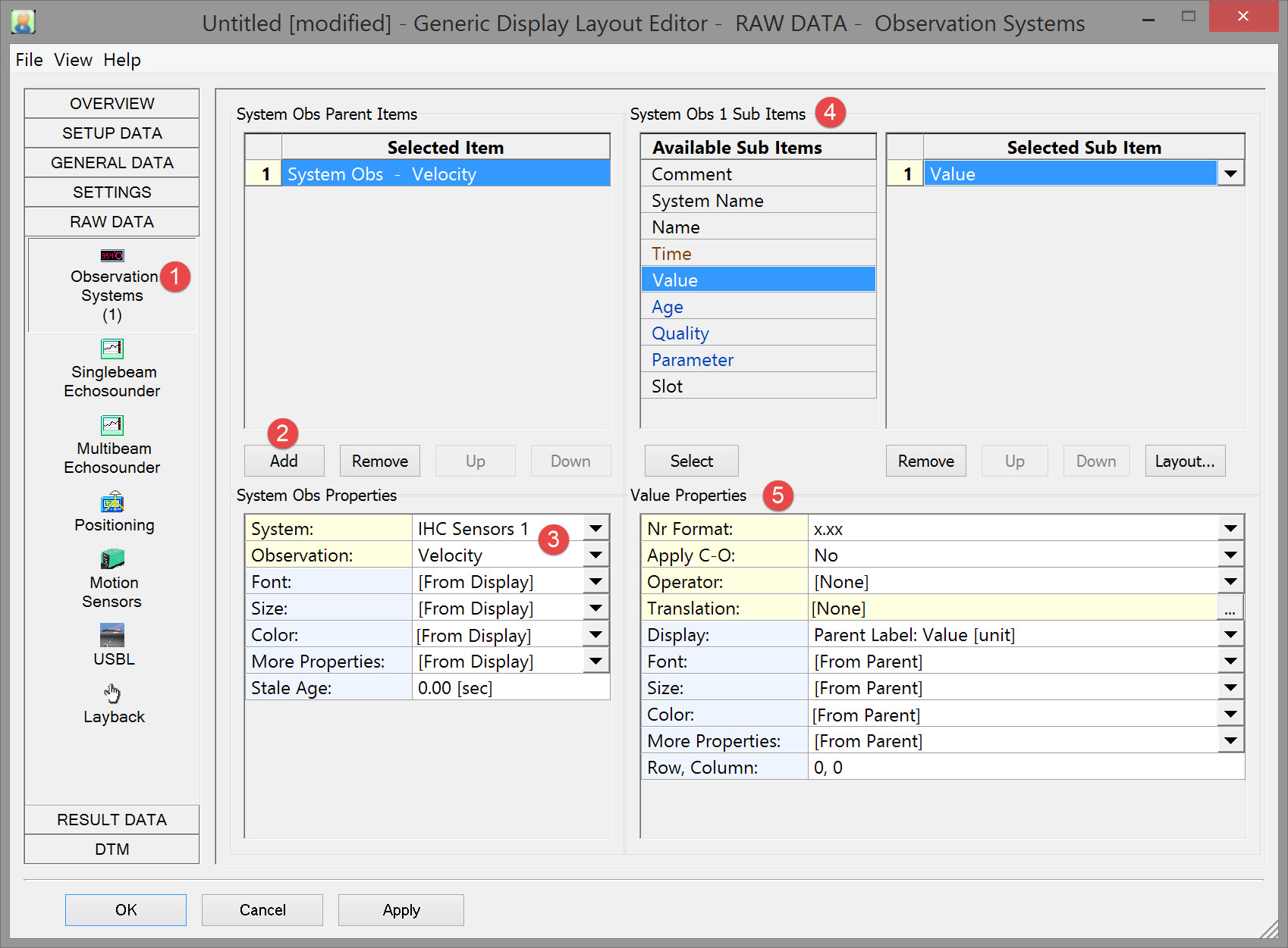
image2016-3-9 10:9:12.png Click on Raw Data and the Observations Systems.

Dredging_GenericDsp_RawData_ObsSys.jpg

image2016-3-8 11:17:51.png Click on AddButton.jpg .

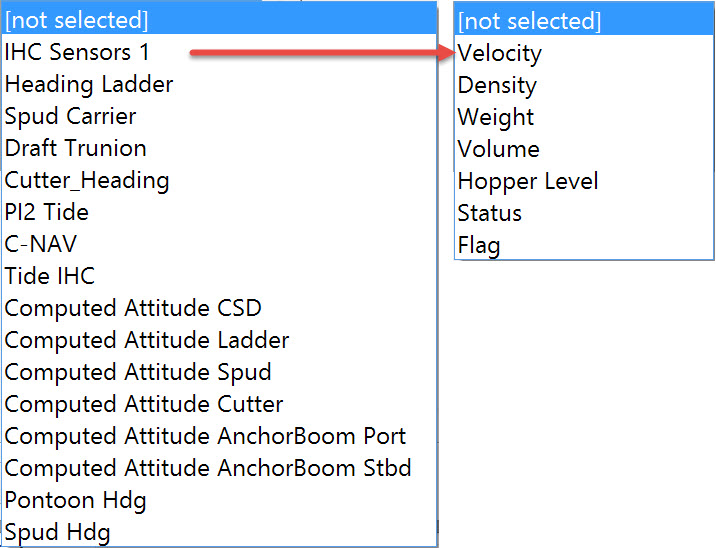
image2016-3-9 10:14:57.png Select a system and an associated observation.These are the observation systems supported:

    • Gyro Compass

    • Underwater Sensor

    • Speed Log

    • Tide Gauge

    • Surface Navigation Systems

    • Magnetometer

    • Miscellaneous Systems

    • Dredging Sensor

    • Rotation Angle Sensor

    • Acceleration Velocity Sensor

Add Velocity and Density from these choices in our example:
Dredging_GenericDsp_ObsSys_DredgeObs.jpg

image2016-3-14 17:26:22.png Select which sub-items to show for each observation. In our example only the value is added.

image2016-3-14 17:40:52.png Set the Properties for each sub-item.

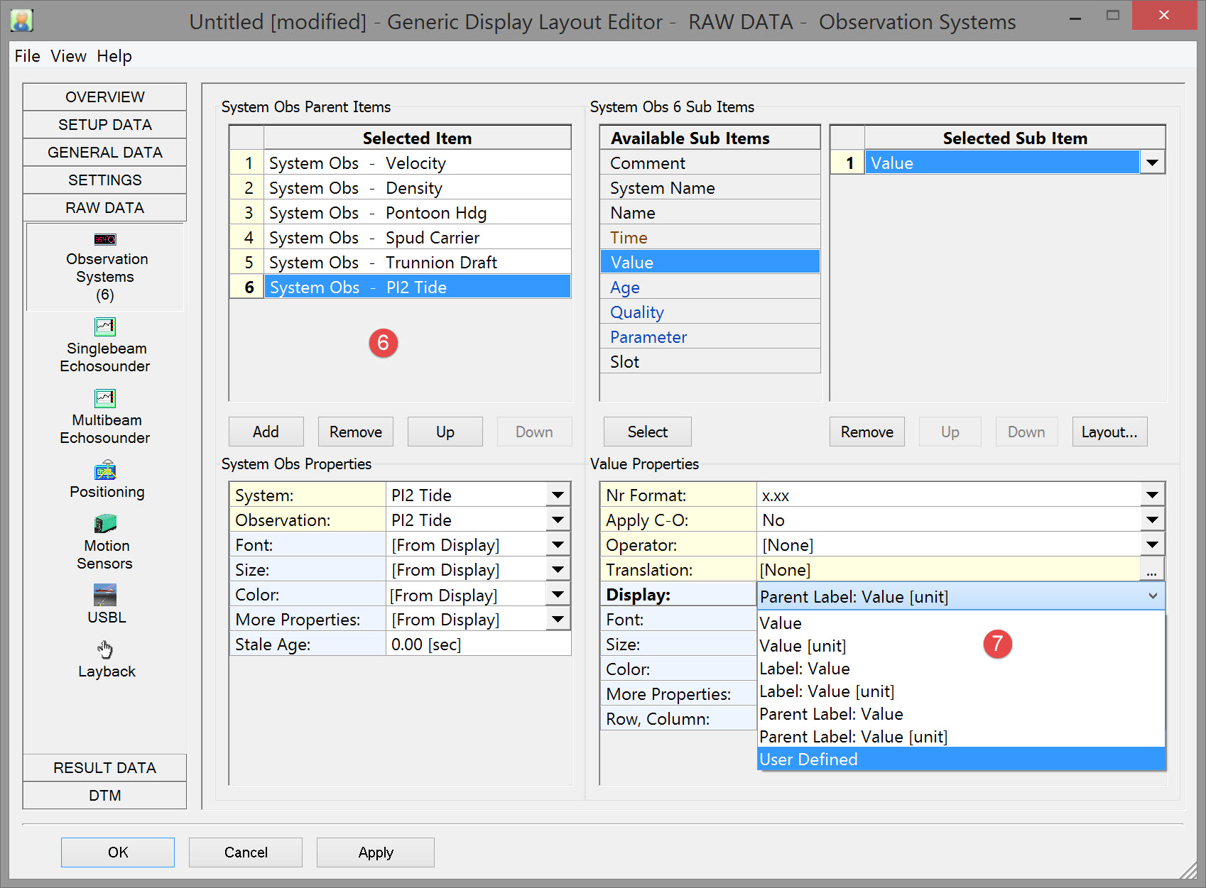
image2016-3-14 17:41:3.png Click on  AddButton.jpg multiple times to add the observation systems and observations shown below. For each add the sub-item 'Value'.

Dredging_GenericDsp_ObsSys_TideLabel.jpg

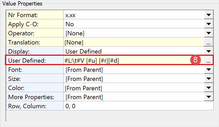
image2016-3-14 17:41:15.png For the Tide System, sub-item 'Value' click on the Display drop down arrow and select User Defined. This changes the options under Properties by adding a line.

Dredging_GenericDsp_PropertiesUserDefinedLine.jpg

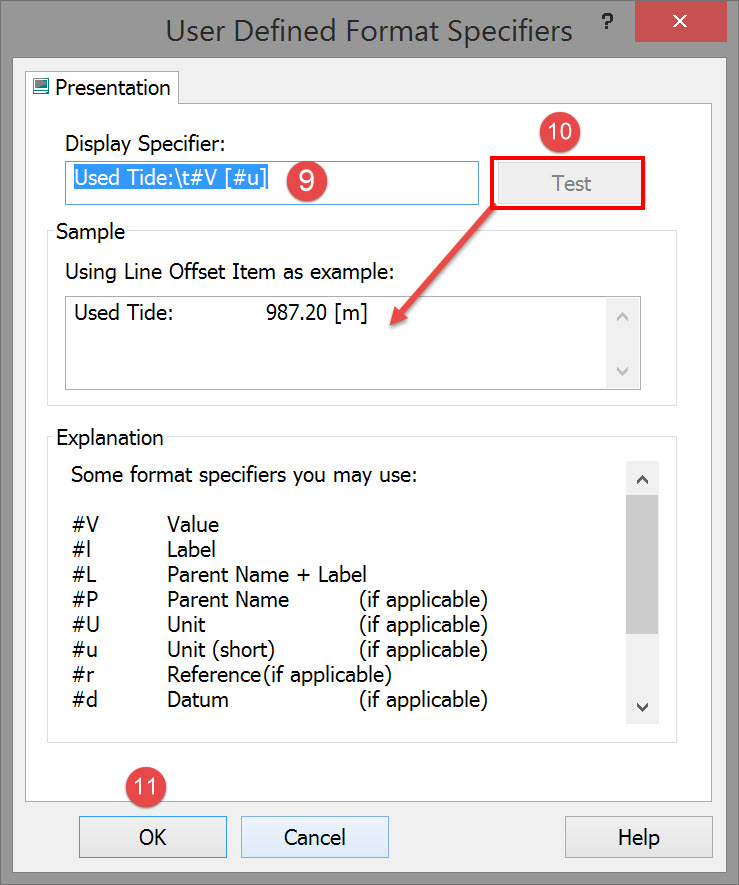
image2016-3-14 17:41:26.png Click on the browse button to open the User Defined Format Specifier dialog.

Dredging_GenericDsp_UserDefinedFormatDialog.jpg

image2016-3-14 17:41:39.png Modify the Display Specifier as shown above. 

image2016-3-14 17:41:50.png Click on Dredging_GenericDsp_TestButton.jpg to check what will be finally displayed is what you want.

image2016-3-14 18:9:34.png Click OK.

Refer to for more information on format specifiers.
Refer to for an explanation of operators acting on data values.

Return to top of page.

Singlebeam Echosounder

No singlebeam echosounder is defined in our example.
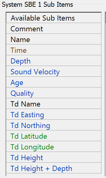
These are the sub-items:
Dredging_GenericDsp_RawSBEsubItems.jpg

Refer to for more information

Return to top of page.

Multibeam Echosounder

List with all available multibeam and multi-transducer echosounder systems that exist in the current selected QINSy database.
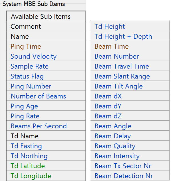
Because different types of multibeam echosounder systems are supported (Ro/Theta, X/Y/Z, Profilers) and multi-transducer systems, some items below may not be applicable for the concerned type.

No multibeam echosounder is defined in our example.
These are the sub-items:
Dredging_GenericDsp_RawMBEsubItems.jpg

Refer to for more information.

Return to top of page.

Positioning

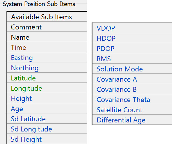
Display of spud pole and dredge head positions are to be added; however, positioning here refers to raw data and results data is preferred.
These are the raw data sub-items:
Dredging_GenericDsp_RawPositionSubItems.jpg

Refer to for more information.

Return to top of page.

Motion Sensors

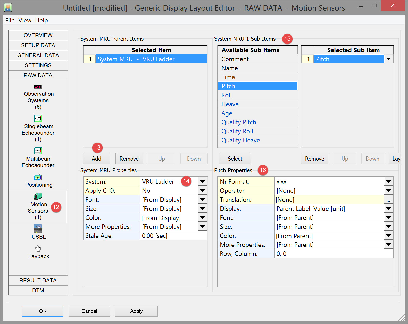
image2016-3-14 18:9:45.png Click on Raw Data and then on Motion Sensors.

Dredging_GenericDsp_RawData_MRU.jpg

image2016-3-14 18:10:1.png Click on AddButton.jpg .

image2016-3-14 18:10:15.png Select the system and decide whether to apply the C-O value.

image2016-3-15 14:23:1.png Double click on the sub-item 'Pitch'.

image2016-3-15 14:23:20.png Modify Pitch Properties if necessary. Refer to for explanations of the various properties.

Refer to for more information.

Return to top of page.

USBL

QINSy may be receiving the positioning of spud and cutter in the form of pseudo USBL measurements, i.e. a dX/dY/dZ measurement from the dredger's CoG point to the spud and/or cutter. Displaying these measurement may be useful.

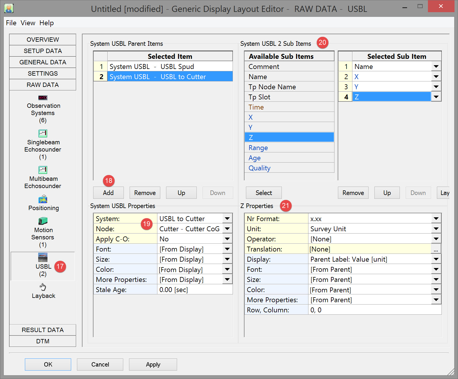
image2016-3-15 14:59:24.png Click on Raw Data and then on USBL (in dredging usually a pseudo-USBL system).

Dredging_GenericDsp_RawData_USBL.jpg

image2016-3-15 14:59:37.png Click on AddButton.jpg .

image2016-3-15 14:59:50.png Select the USBL system and the target node.

image2016-3-15 15:0:1.png Select the associated sub-items, in this case the name, to distinguish it from the other USBL system and the X/Y/Z values.

image2016-3-15 15:0:16.png Modify the Properties if necessary. Refer to for explanations of the various properties.

Refer to for further explanation.

Return to top of page.

Layback

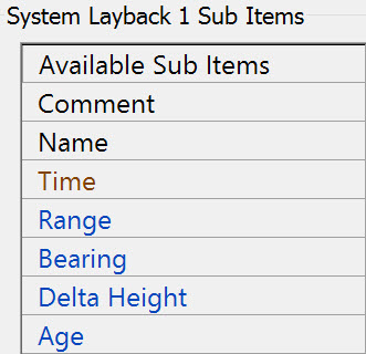
No Layback system is defined in our example.
These are the sub-items:
Dredging_GenericDsp_RawData_LaybackSubItems.jpg

Refer to  for more information.

Return to: top of page

Return to: CSD - Generic Display