
Alphanumeric Display
This Display can be configured to show a great many of the parameter values handled by the acquisition software, including various dredging related information.
The text style layout is fully configurable, as is the font itself and the color used for each item. Background color is also changeable.
Display content and layout can be printed and/or stored to file at intervals based on user-definable criteria.
The Generic Display is used for the same purpose and has many more options. As such it may prove more flexible to use than the Alphanumeric which is being phased out.
Create the Display
Take the following steps in order to create an Alphanumeric display.


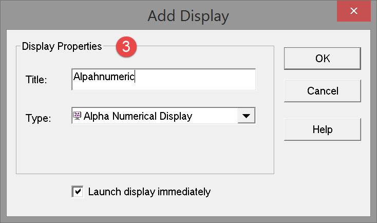

Pressing OK opens an empty dialog and the first of seven pages of a setup wizard.
Return to top of page.
Wizard Pages
When creating this display for the first time a seven page Setup Wizard is employed to select parameters and enter values.
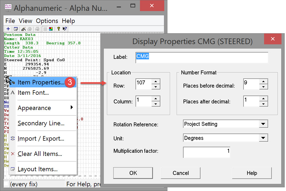
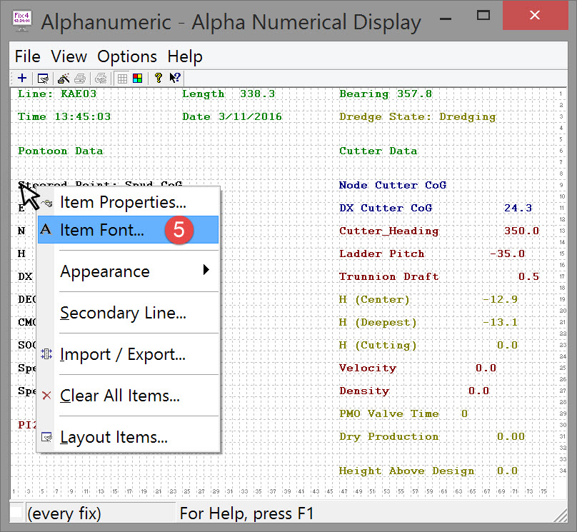
On completion of the wizard, selected items are shown in the Display itself. At that point the properties and font of any item are editable by right clicking on the item and selecting from the context menu.
Alternatively icons in the toolbar can be used to edit the various pages separately.
|
Command |
Description |
|---|---|

|
Opens the wizard on Page 1. All previously selected items are still there. New items can be added to, and original items deleted from the layout. |

|
Opens page 7, the Layout page, directly for layout editing/reformatting. |

|
Open the Fix Printout Settings dialog in which data printing options (what and when) are defined. |

|
Turns printing on and off. |

|
Used to manually initiate a printout using the F12 function key. |

|
Turns the grid on and off. A grid is very useful when manually moving items around using the mouse. |

|
Used to change the background color. |
|
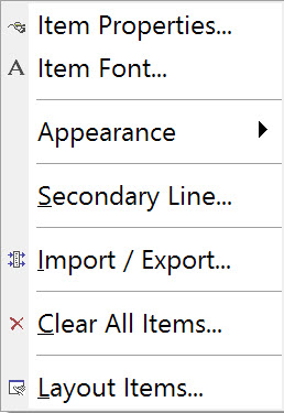
Item Properties - modification of item name, location (by row and column numbers), number format, units and multiplication factor. Item Font - modification of font, font style, size, effect (strikeout/underline) and script. Appearance - turn grid on/off and change background color. Secondary Line - there may be occasions when one object is referenced to the main line, and a second line is need as reference for a second object. Use this option to select the secondary line. Import/Export - once completed a layout may be saved to a configuration file which can later be imported when required, so avoiding a repeated setup procedure. Clear all items - does what it says. Layout Items - opens the layout wizard on Page 1. |
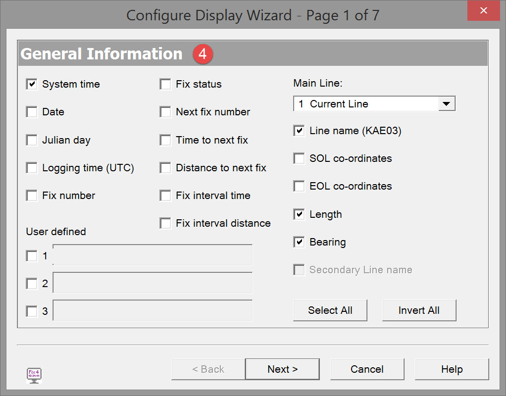
Page 1 - General Information

Displayed parameters for line information could differ from that what you see in the dialog, depending on the selected Current line type (point/line/route) in the Session setup .
Click 
Return to top of page.
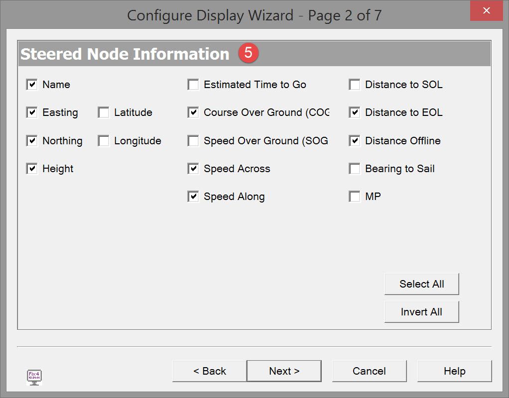
Page 2 - Steered Node Information

The Steered Node is selected in Computation Settings in the Controller.
Displayed parameters could differ from that what you see in the dialog, depending on the selected Current line type in the Session setup .
Important: Computed parameter values depend to a large extent upon the settings in Computation Settings - Position Filter/Position Results.
For example, the default number of position updates that are used to compute SOG/COG is 5; these values are used in turn to compute the other parameters.
To avoid 'jumps' or slowly changing values that do not reflect reality, it may be necessary to change filtering settings to obtain meaningful values
Latitude/Longitude formatting is selected on the last page of the wizard (decimal seconds, decimal minutes or decimal degrees).
In case the selection is a route, the parameter values are calculated to the beginning or the end of the active section of the route.
Click
Return to top of page.
Page 3 - Other Node Information

You can only select nodes under 'Available Nodes' AFTER selecting which computation to use from the 'From' drop down list.
You can only select nodes from ONE adjustment. Selecting node(s) from another adjustment clears the original selection.
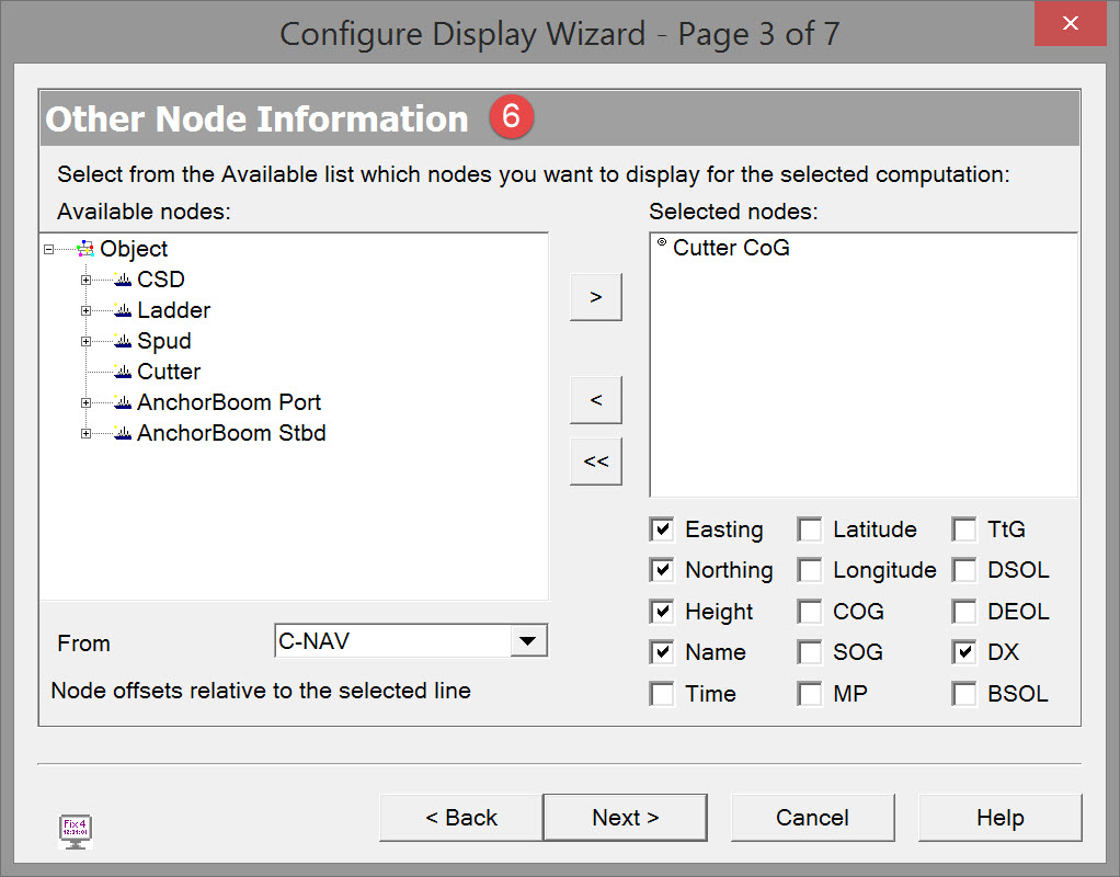
Easting, Northing, Latitude, Longitude and Height parameters are shown for each selected node. Other parameters shown for each node depend upon whether a point / single line / route is selected as the Current Line (Session Setup, Controller) / Secondary Line (Settings menu).
All distances are in survey units and all bearings are grid and in degrees.
Click
Return to top of page.
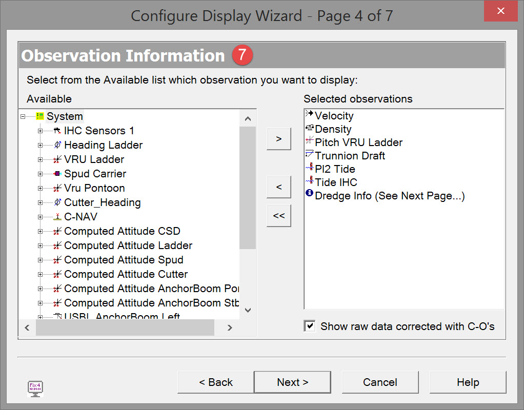
Page 4 - Observation Information

For access to dredging related parameters, make sure to select dredging sensor and dredging system observations on this page.
Click
Return to top of page.
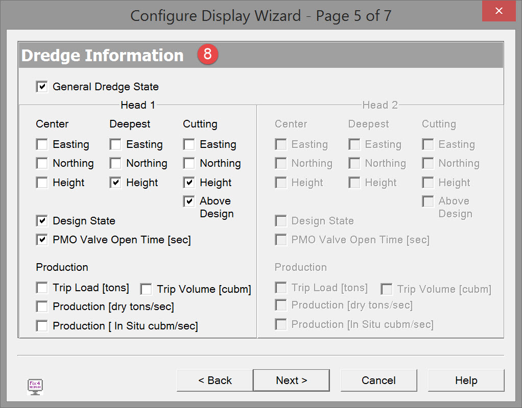
Page 5 - Dredging Information
This page is only available when a dredging system is selected in the Observation Information page above.
If a dredge system with two dredge heads is selected in Database Setup, information for “Head 2” is also be available.

|
General Dredge State |
Display whether the vessel is dredging, dumping, sailing, etc..
|
|
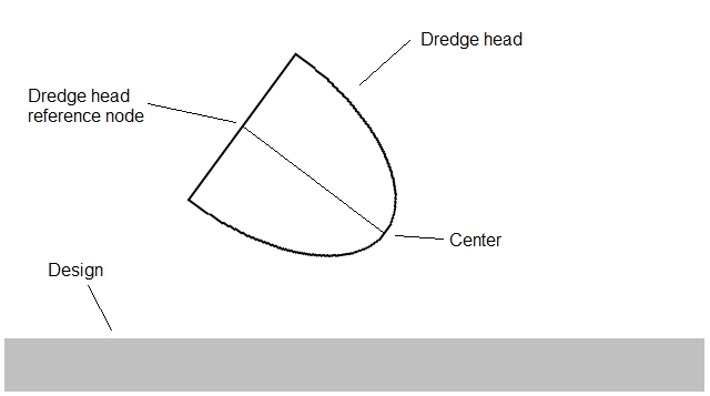
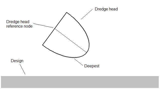
Center E, N, H |
Easting, Northing and Height of the center of the dredge head.
|
|
Deepest E, N, H |
Easting, Northing and Height of the cutting point of the dredge head or the point that is closest to the design.
|
|
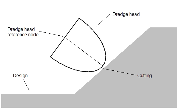
Cutting E, N, H |
Easting, Northing and Height of the cutting point of the dredge head or the point that is closest to the design.
|
|
Above Design |
The height of the cutting point above or beneath the design. |
|
Design State |
Shows:
|
|
PMO Valve Open Time |
This displays the time the Poor Mixture Overboard valve is opened. |
|
Trip Load [tons] |
The total weight that is dredged with this dredge head. |
|
Trip Volume [cubm] |
The total volume that is dredged with this dredge head. |
|
Production
|
The current production that is achieved with this dredge head. |
|
Production
|
The current production that is achieved with this dredge head based on the In Situ Density.
|
Click
Return to top of page.
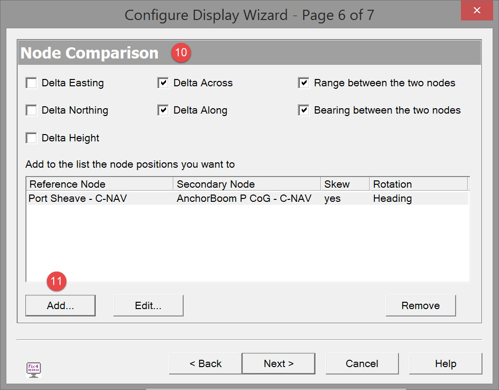
Page 6 - Node Comparison
The calculated differences between two nodes. Values are FROM the Reference Node TO Secondary Node.


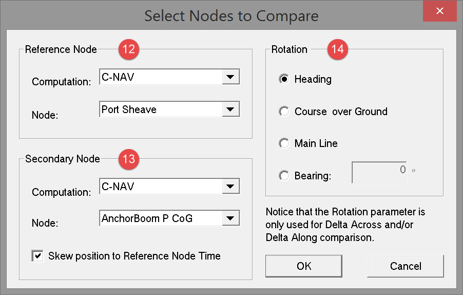


whether this is the heading of the object upon which the reference node is located, the CoG of that object, a main line bearing, or a particular set bearing.
Click OK.
Back on Page 6 of the wizard, click
Otherwise click
Return to top of page.
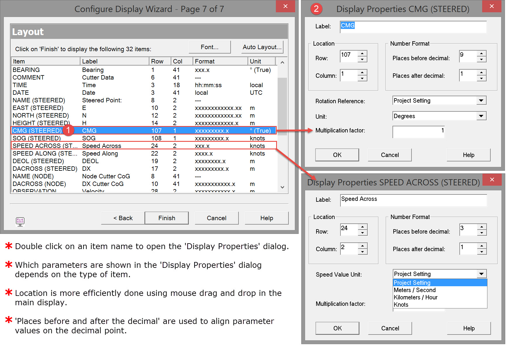
Page 7 - Layout
The items selected in the prior six pages are listed in the order they were selected.
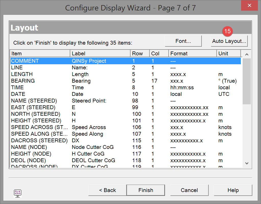

In the Auto Format Dialog just click OK to start with.
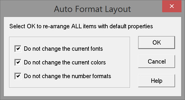
Back on Page 7 of the wizard click 
Return to top of page.
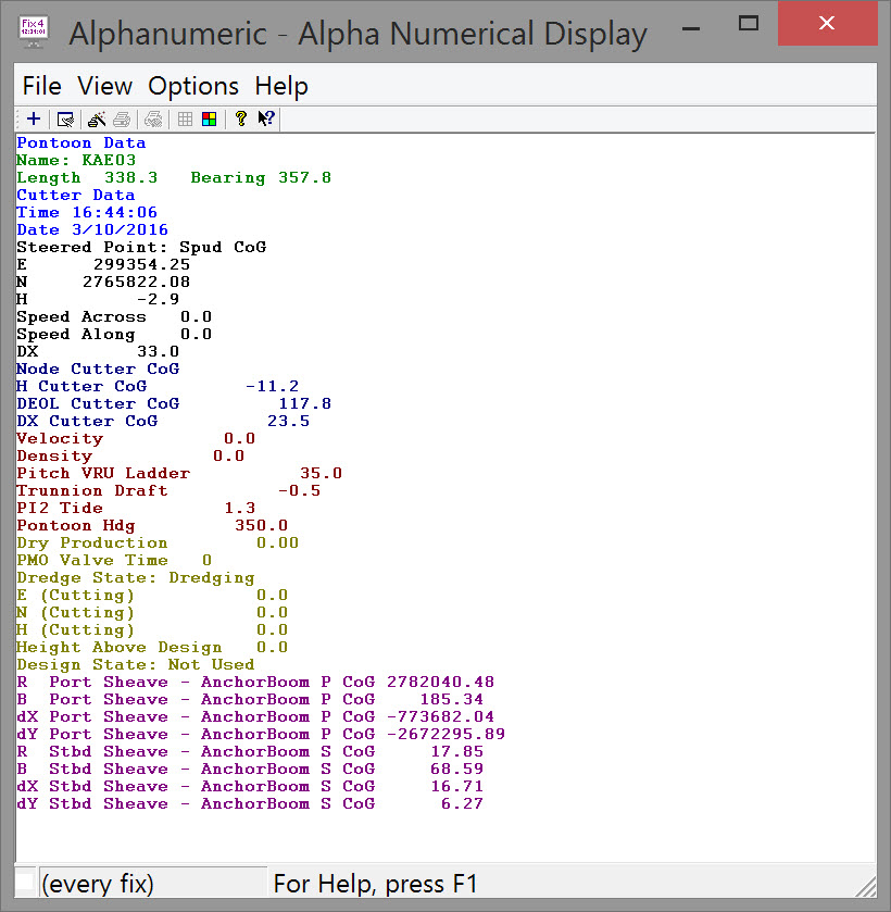
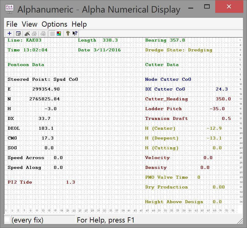
Changing the Layout
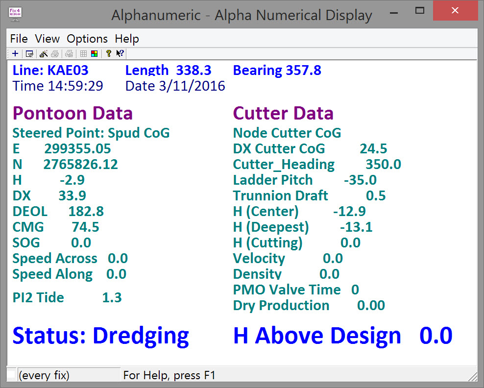
Inevitably the initial layout needs modification. Most of the tools are fairly self explanatory and easy to use. An actual example - the display above - may help to clarify some options.
Since you have a working layout after going through the wizard, save the current layout before changing anything using the Import/Export command in the options menu. That way you can revert if the modifications become messy and you want to start over.
*.LSF files are stored in \Current Project\Support.
As you continue to modify the look of the display re-export periodically to *.lsf files with different names, e.g. Alphanumeric_R1.lsf, Alphanumeric_R2.lsf, Alphanumeric_R3.lsf, etc..
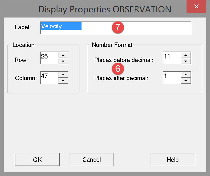
Display Properties

Return to top of page.
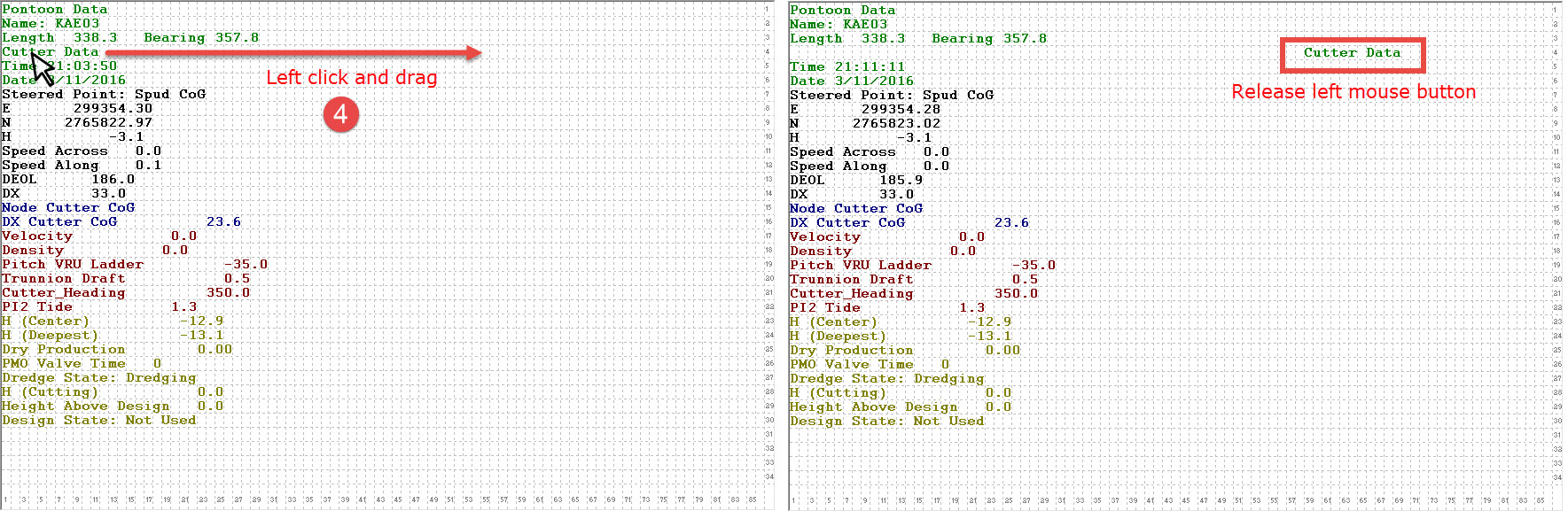
Mouse Drag and Drop
Using the left mouse button to drag and drop an item is perhaps the most important tool for editing the layout.
Activating the grid pattern (
Quite often items must be 'parked' in temporary locations to free up space for moving another item.
Continue moving items around until you are happy with the layout.
You may also want to modify font and text size so bear that in mind when placing items.
A revised layout may look something like this before font size changes:
Return to top of page.
Font Size and Color

To change fonts for multiple items at once use the standard windows SHIFT and CTRL keys to make item selections in the Layout page.
In changing font size it may become necessary to move items around again, e.g.

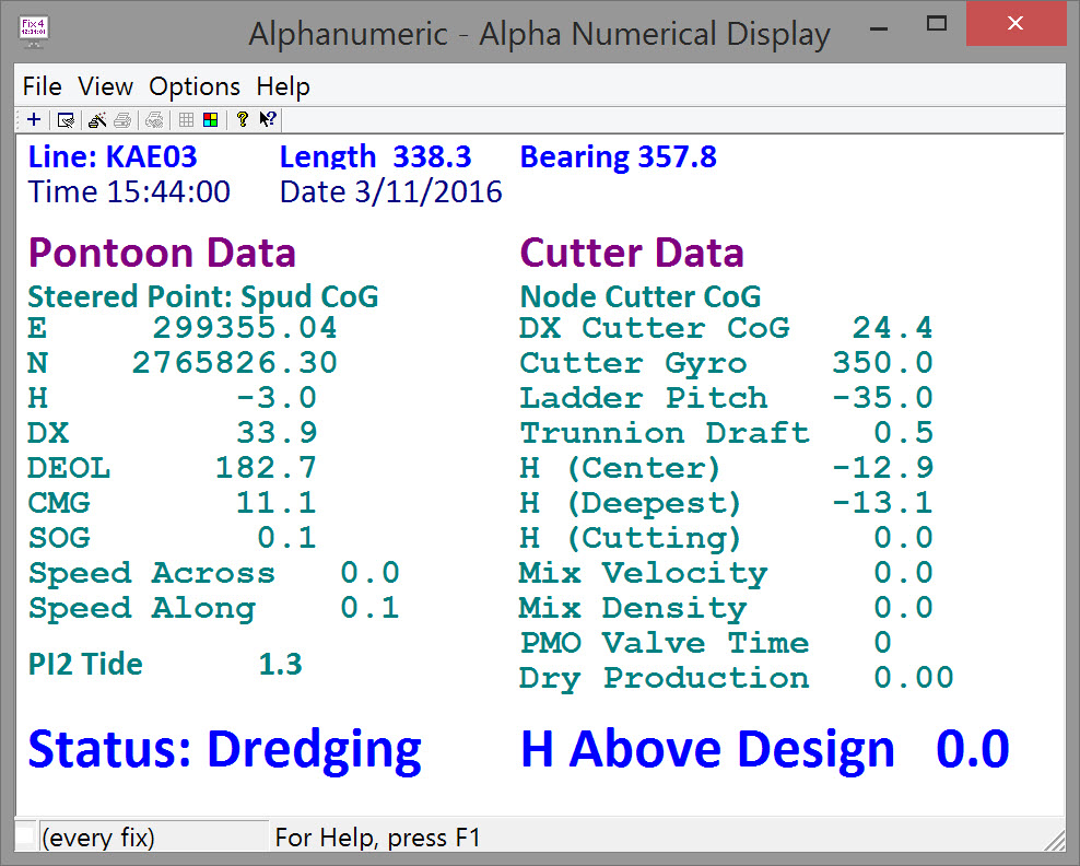
After text size and color modification you might end up with something like this:
Return to top of page.
Aligning Data Values
Aligning the decimal points of the data values in the display above would probably improve the presentation somewhat. Do this by right clicking on each item and selecting Item Properties, or use the task bar icon
Be warned that the task can be a bit painstaking! And, depending on the font used, you may never achieve an exact alignment!
The best bet for aligning is to use New Courier.
Return to top of page.
Data Output & Storage
Options for output of data to printer (hard copy) and/or to file are accessed using the Fix Printout Settings dialog, either from the File menu or by using the task bar icon
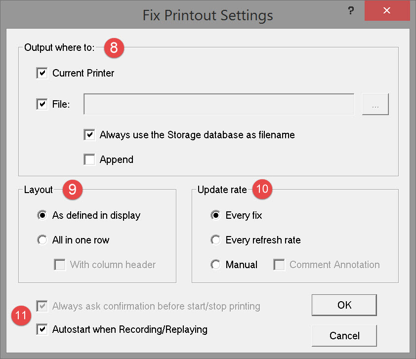


|
Every fix |
Output every time a fix is generated. Fix interval is set in Session Settings - Fixing, and can be based on manual, time, distance or an external trigger. |
|
Every refresh rate |
Output according to the Refresh Rate set in the View menu. |
|
Manual |
Output only when a manual fix is generated by pressing the hotkey F12. |
|
Comment Annotation |
Option to edit the user-defined comments on the Manual fix printout. |


If 'Always ask confirmation before start/stop printing' is checked and the Fix Printout Now 
Do not forget to switch on printing
Return to: top of page
Return to: CSD - Online Displays