
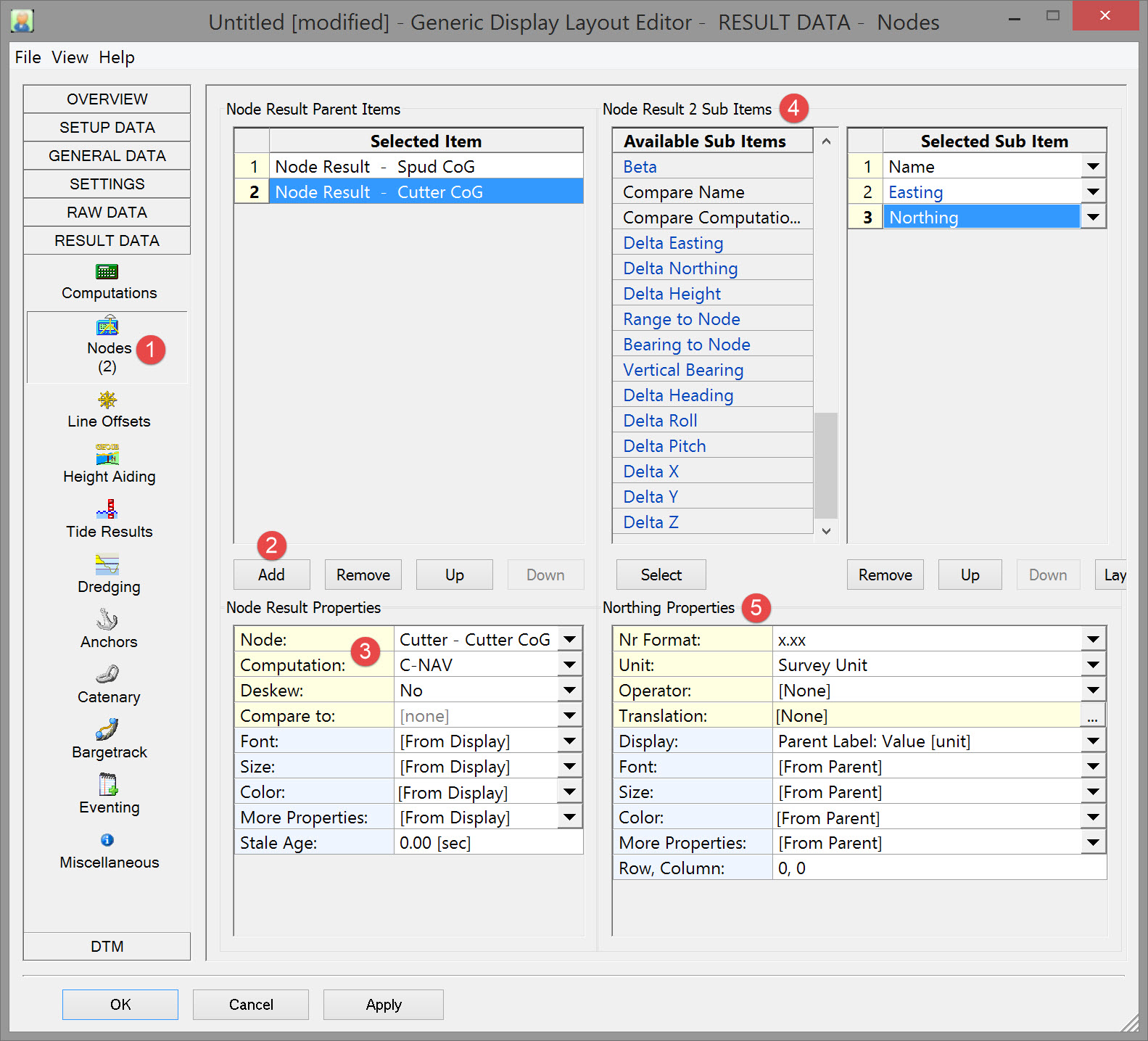
Selecting Result Data Items
Select items from:


Obviously not all these apply to dredging operations. The following are not considered here: Anchors, Catenary, Bargetrack, Eventing, Miscellaneous.
Deskewing means calculating a 'new' position (using SOG and COG) for the time of trigger. This trigger can be On Time, On Fix, On Node Result update or On System update.
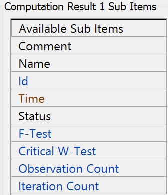
Computations
These are the sub-items associated with a Computation. The need to select any one of them is remote in dredging.
-
The first entry is always [Priority List]. This means that the computation with the highest priority, as defined in the Controller's Computation Setup, will be used.
-
The rest of the list will show all available computations, as defined in the Controller's Computation Setup of the current selected QINSy database
Refer to for further information.
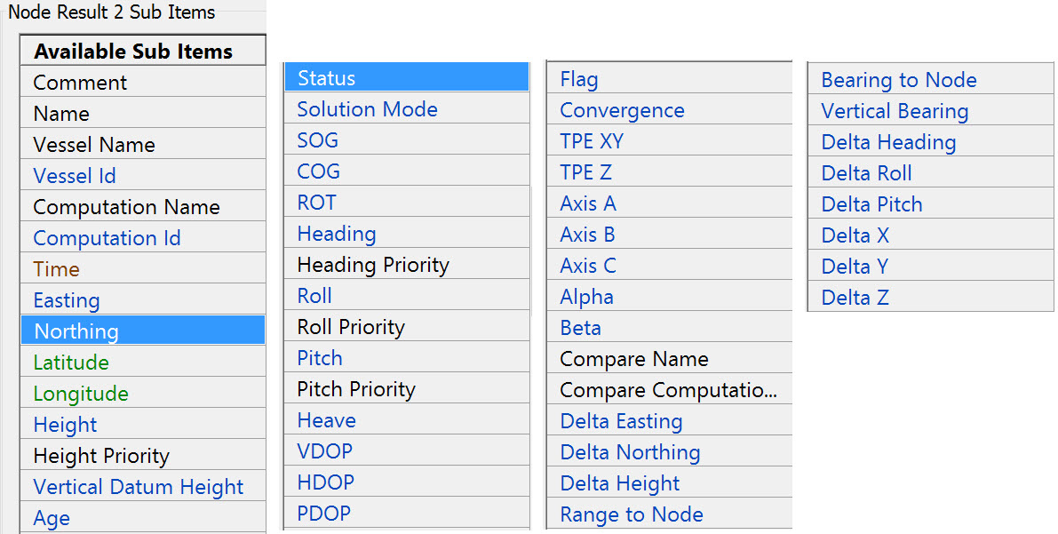
Nodes
The first entry is always [Steered Node]. It can be changed if the position of the steered node is not required.
In our example the Spud CoG is the steered node.


These are all the sub-items available:

Refer to for further information.
Return to top of page.
Return to CSD - Generic Display.
Line Offsets
A list with 10 entries. The first one is always the Controller's mainline.The other 9 are the Additional mainlines.
The actual mainline/additional mainline selection (POINT, LINE, ROUTE) is done in the Controller's Session Setup.

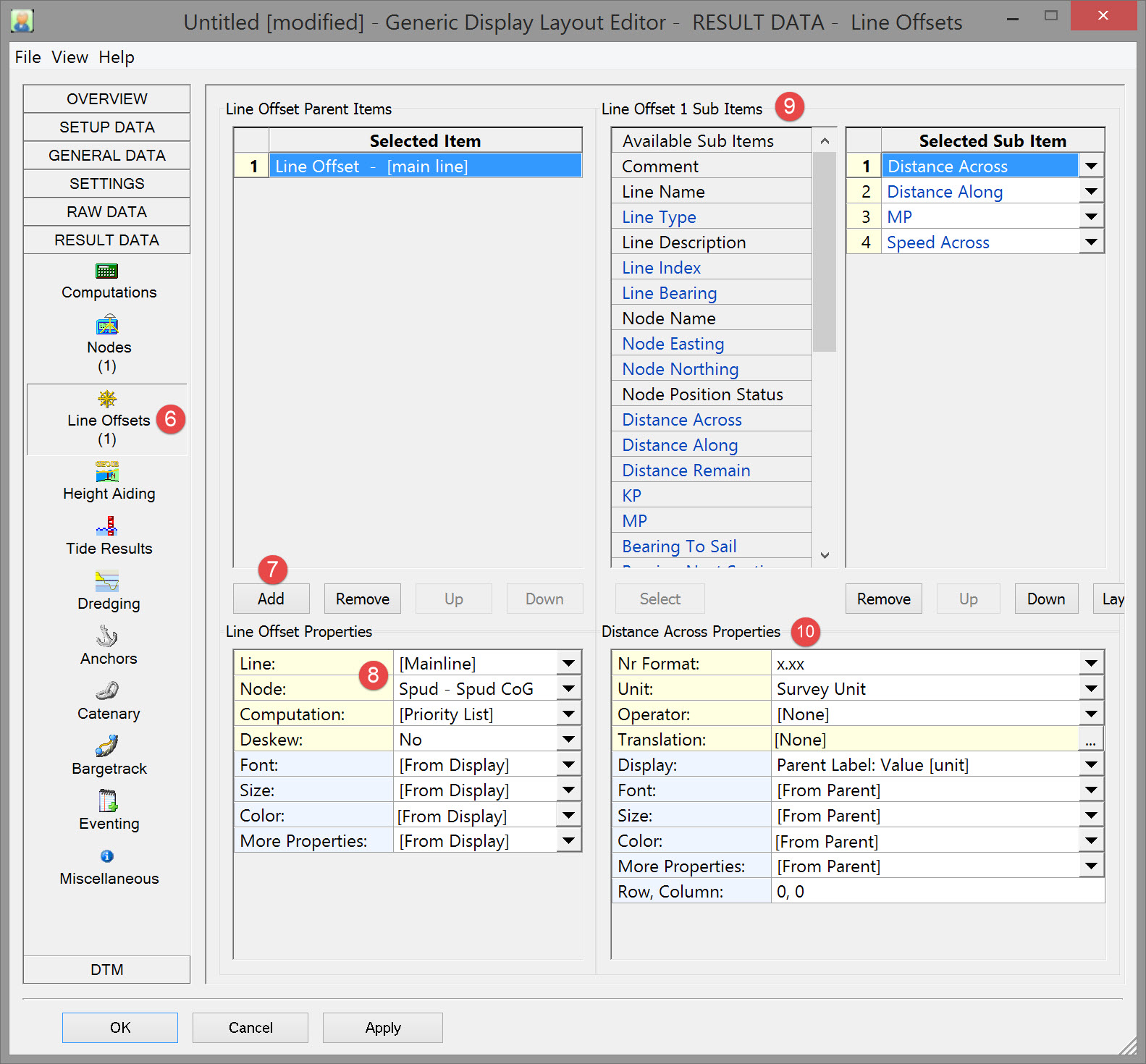


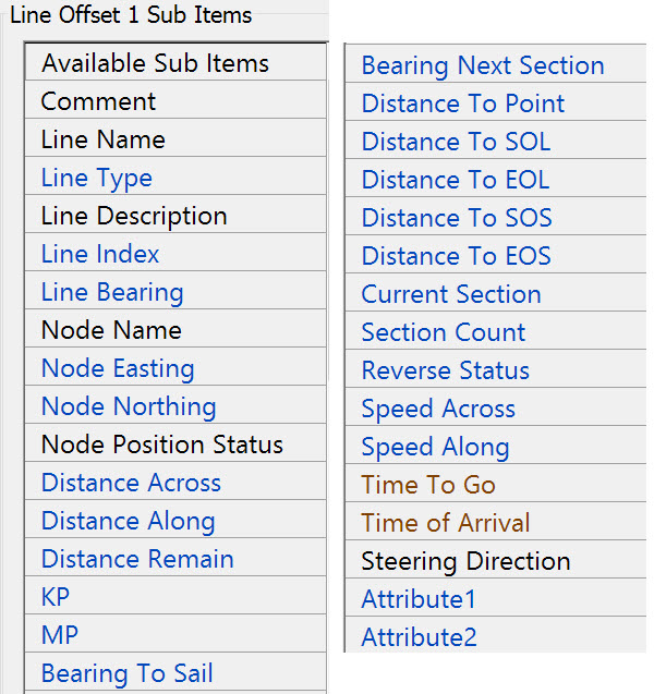
These are the available sub-items:

Refer to for further information.
Return to top of page.
Return to CSD - Generic Display.
Height Aiding

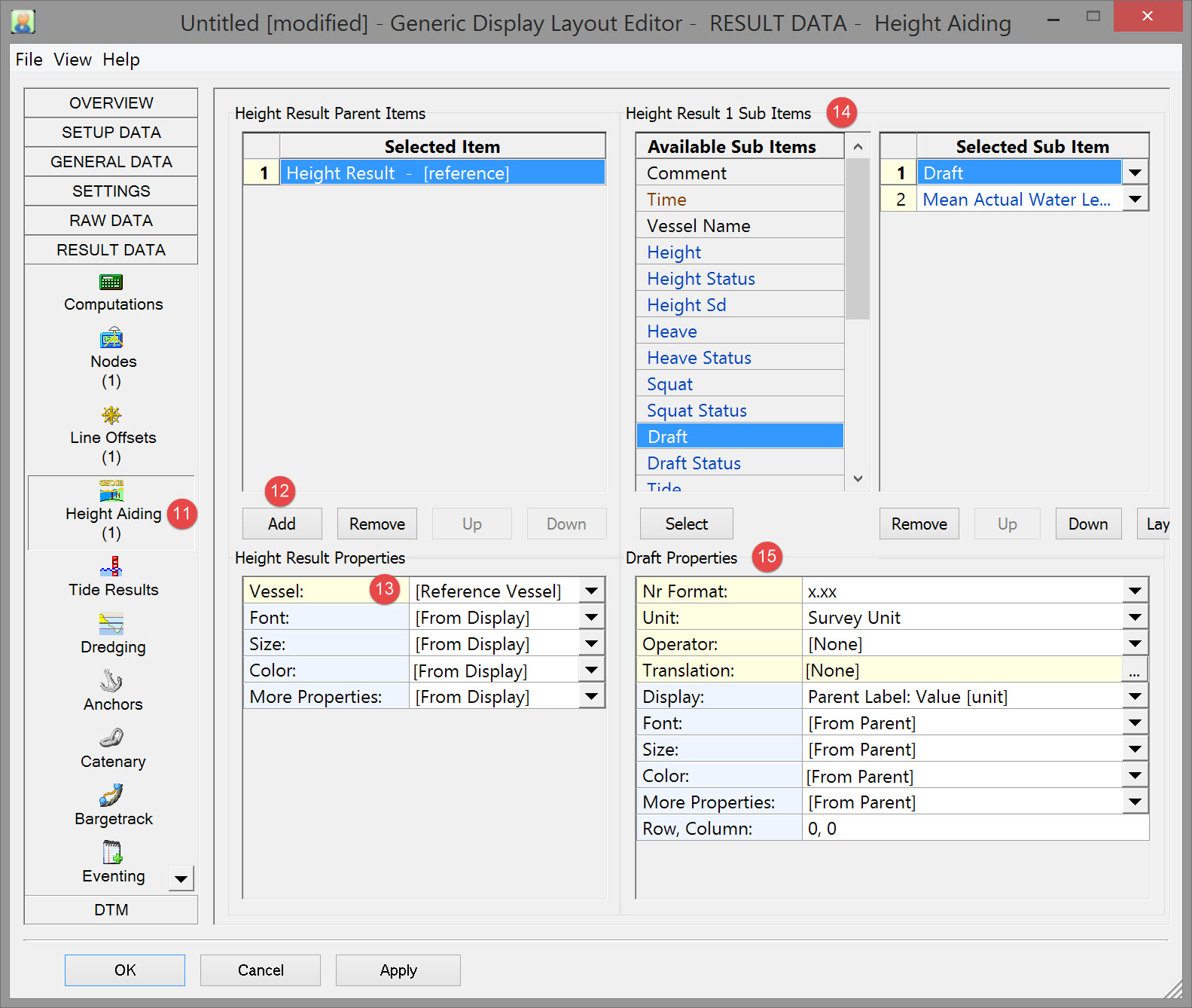


In Database Setup you will see 'square' icon in front of the vessel name.
The rest of the list will show all available objects existing in the current selected QINSy database.

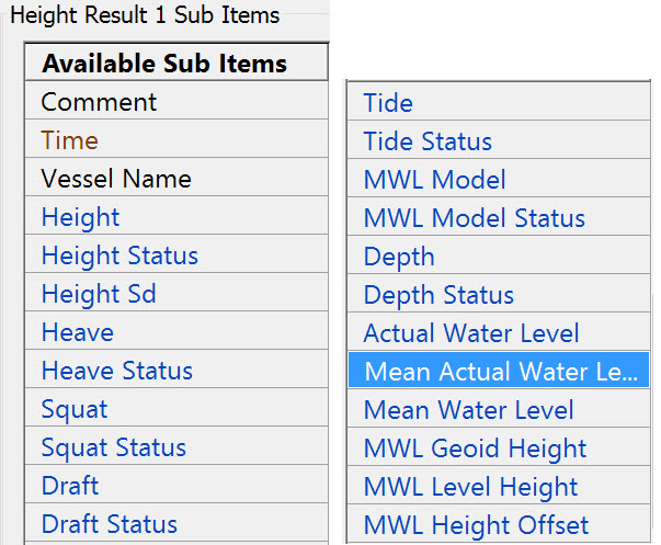
Draft - The instantaneous actual water level above Vertical Datum.
Mean Actual Water Level - The Actual Water Level minus the heave of the object, so i.e. the actual water level without the swell influence.
These are the available sub-items:

Refer to for more information.
Return to top of page.
Return to CSD - Generic Display.
Tide Results
The first entry is always [Reference Vessel]. This means that the first defined object will be used (with Object Id 1).
In Db Setup you will see 'square' icon in front of the vessel name
The rest of the list will show all available objects, existing in the current selected QINSy database.
These are the sub-items:
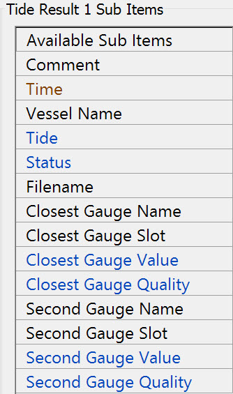
Tide: This is the tide component of the Height Aided Observation, on Survey Datum. This observation is calculated by the Height Aiding driver (which is always present in the Windows taskbar).
Notice that this item is the same as item Tide under Height Aiding.
Refer to for more information.
Return to top of page.
Return to CSD - Generic Display.
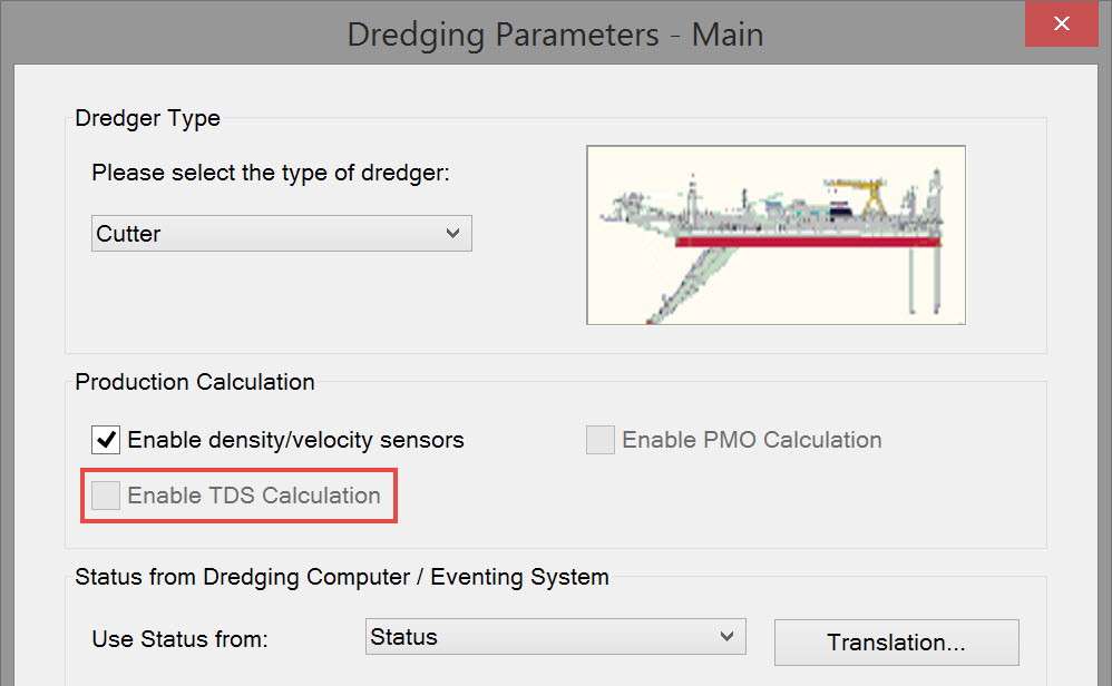
Dredging Results
Lists all available dredging systems that exist in the currently selected QINSy database.

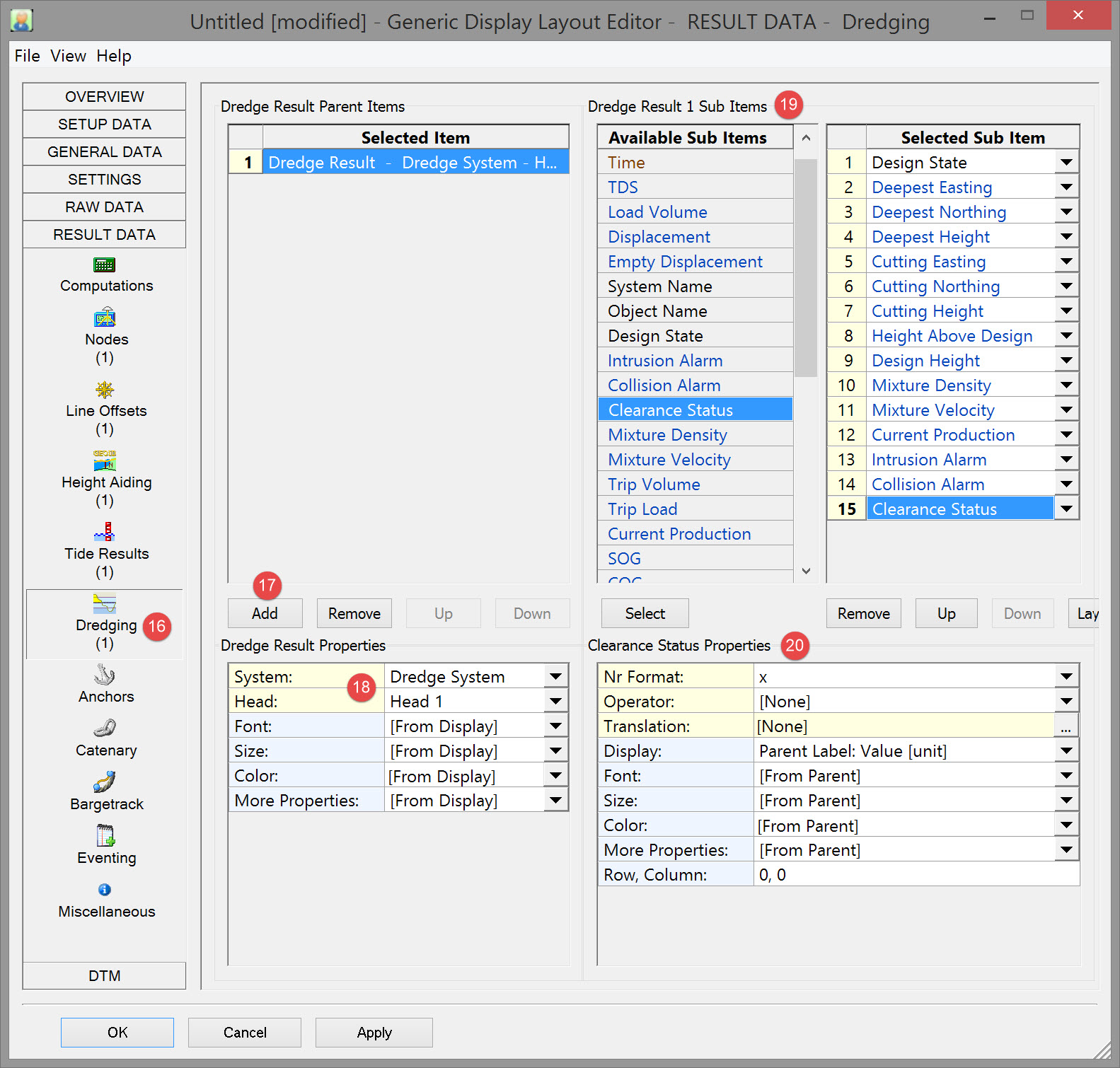


Most sub-items below are 'connected' to a particular head, but some are head independent, i.e. it does not matter whether Head 1 or 2 is selected.
The presence of Head 2 depends on the type of dredger (backhoe, cutter, hopper, etc.), as defined in the Database Setup.

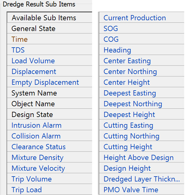
Notes on sub-items:
|
Sub-item |
Description |
|||||||||||||||||||||
|---|---|---|---|---|---|---|---|---|---|---|---|---|---|---|---|---|---|---|---|---|---|---|
|
General State
Item is head independent.
|
|
|||||||||||||||||||||
|
Time
Item is head independent. |
Update time of the dredging driver. |
|||||||||||||||||||||
|
TDS
Item is head independent.
|
Tons Dry Solid in [tons]
|
|||||||||||||||||||||
|
Load Volume
|
Actual Load Volume in [tons]
|
|||||||||||||||||||||
|
Displacement
|
Actual Displacement in [tons]
|
|||||||||||||||||||||
|
Empty Displacement
|
Empty Displacement in [tons]
|
|||||||||||||||||||||
|
System Name |
The name of the selected Dredging System, as defined in the Database Setup program. |
|||||||||||||||||||||
|
Object Name |
The name of the object on which the selected head is located, as defined in the Database Setup program. |
|||||||||||||||||||||
|
Design State |
|
|||||||||||||||||||||
|
Intrusion Alarm
(Used to be known as Emergency Hoist Alarm in previous versions)
|
Value depends on the Horizontal Clearance Error, which is set in the Controller Session Setup, Dredging, Intrusion Detection page.
Same alarm as seen in Alert Display, Category "Dredging Result", Type: "Intrusion Detection: Error (Emergency Hoist)" |
|||||||||||||||||||||
|
Collision Alarm |
Value depends on the Horizontal Clearance Warning, which is set in the Controller Session Setup, Dredging, Intrusion Detection page
Same alarm as seen in Alert Display, Category "Dredging Result", Type: "Intrusion Detection: Warning" |
|||||||||||||||||||||
|
Clearance Status A combination of Intrusion and Collision Alarms |
Value depends on the Horizontal Clearance Warning, Horizontal Clearance Error and/or Vertical Clearance, all set in the Controller Session Setup, Dredging, Intrusion Detection page.
|
|||||||||||||||||||||
|
Mixture Density |
Current mixture Density from production sensor, (C-O) already applied |
|||||||||||||||||||||
|
Mixture Velocity |
Current mixture velocity from production sensor, (C-O) already applied |
|||||||||||||||||||||
|
Trip Volume |
Current volume inside the selected dredging system |
|||||||||||||||||||||
|
Trip Load |
Current load inside the selected dredging system |
|||||||||||||||||||||
|
Current Production |
Current production, derived from production sensors
|
|||||||||||||||||||||
|
SOG |
Speed over ground of the reference node of the selected head object |
|||||||||||||||||||||
|
COG |
Course over ground of the reference node of the selected head |
|||||||||||||||||||||
|
Heading |
Grid heading of the selected head object |
|||||||||||||||||||||
|
Center Easting/Northing/Height |
Coordinates of the dredge head CoG. |
|||||||||||||||||||||
|
Deepest Easting/Northing/Height |
Coordinates of the deepest point of the dredge head. |
|||||||||||||||||||||
|
Cutting Easting/Northing/Height |
Coordinates of the cutting point of the dredge head. |
|||||||||||||||||||||
|
Height Above Design |
Actual height minus the design height at footprint of the selected head.
|
|||||||||||||||||||||
|
Design Height |
Height of design at footprint of the selected head.
|
|||||||||||||||||||||
|
Dredged Layer Thickness |
Amount of removed soil.
|
|||||||||||||||||||||
|
PMO Valve Time |
Total time that PMO (Poor Mixture Overboard) was open (Spilling overboard). |

Return to top of page.
Return to CSD - Generic Display.
Anchors

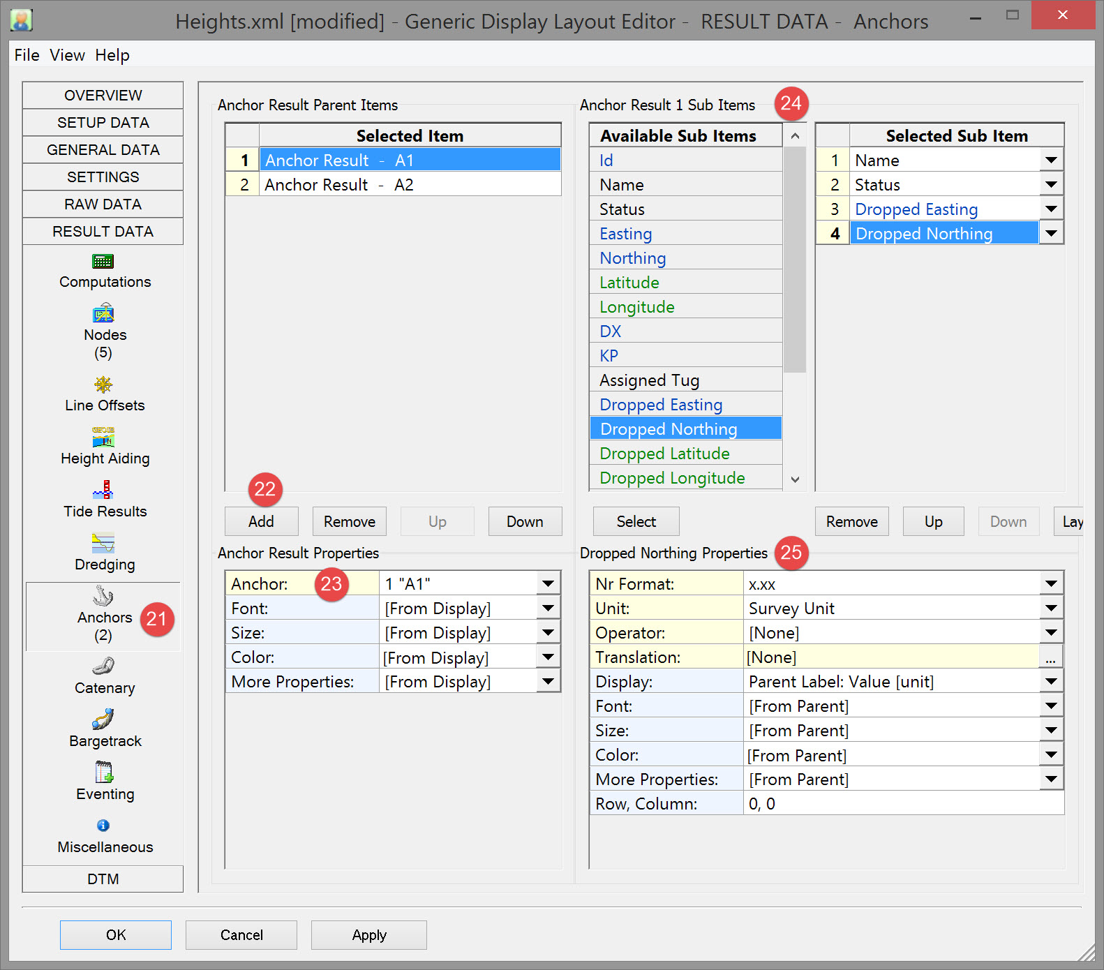


Individual anchors as defined in the Controller's Session Anchor Setup of the currently selected QINSy database are shown in the drop down list.

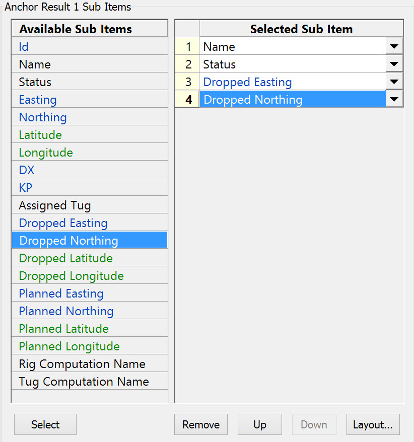
Notes on sub-items:
|
Id |
Id of defined anchor, as given by the Controller's Session Anchor Setup.
|
|
Status |
Current status of the defined anchor. The following labels are possible:
|
|
Easting
|
What these values are depends on the current state of the anchor:
Grid co-ordinates are always on survey datum.
|
|
KP |
Notice the additional Nr Format Property: "Station+Offset (US notation)".
|
Return to top of page.
Return to CSD - Generic Display.
Catenary
Not applicable to dredging.
Return to top of page.
Bargetrack
Not applicable to dredging.
Return to top of page.
Eventing
To be added.
Return to top of page.
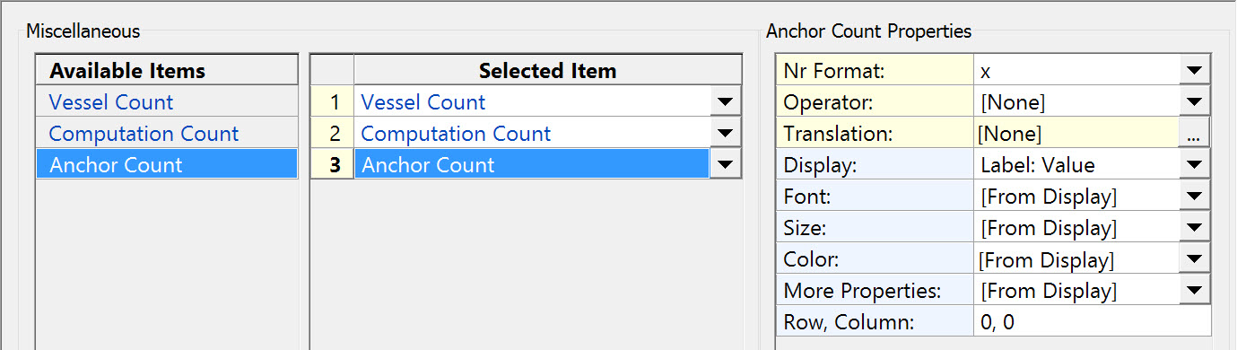
Miscellaneous
Return to: top of page
Return to: CSD - Generic Display