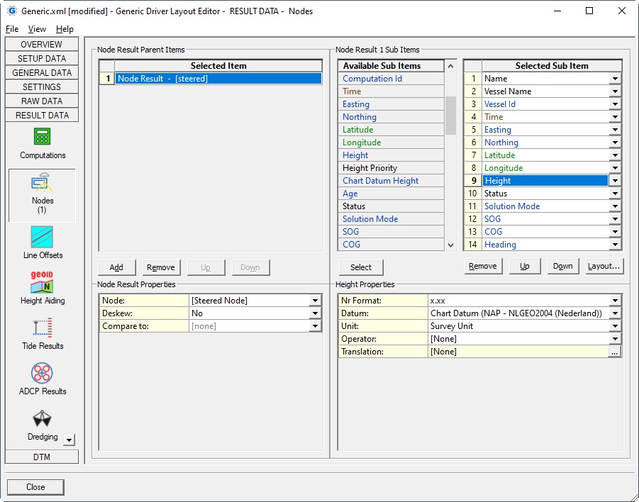
Nodes
| Parent Item | ||
|---|---|---|
Node: |
| |
Computation: | This option to select a computation is only available when a 'real' node is selected in the Node selection above.
| |
Deskew: |
Notes:
Note that terminology 'Deskew' and 'Skew' means the same in Qinsy: they are not opposites of each other. | |
Compare to: | For Node Comparison the following sub items are available: Compare Name, Compare Computation Name, The results of the first selected node (reference node) will be compared with the results of this 'Compare to' node. Note that for node comparison also a fixed node can be selected. For ALL comparison items the following formula is used: 'Compare to' - 'Node'. With other words: the value of the the selected 'Compare to' node MINUS the value of the reference node (the first one).
| |
Orientation: | The orientation property will be visible when a 'Compare to' Node is selected and only applicable for sub item Delta X, Delta Y, Delta Z and Angle.
See the relevant sub item below for more information about this property's behavior. |
| Sub Item | Description | Value Type | ||||||||||||||||||||||||||||||||||
|---|---|---|---|---|---|---|---|---|---|---|---|---|---|---|---|---|---|---|---|---|---|---|---|---|---|---|---|---|---|---|---|---|---|---|---|---|
Comment | User defined text
| text | ||||||||||||||||||||||||||||||||||
Name | Name of the node, as entered in Database Setup | text | ||||||||||||||||||||||||||||||||||
X Offset | The cross-line offset of the selected node from the object reference point as defined in the Database Setup. A positive value means that the node is starboard (right-side) and a negative value means that the node is port (left-side) of the object reference point. | double | ||||||||||||||||||||||||||||||||||
Y Offset | The inline offset of the selected node from the object reference point as defined in the Database Setup. A positive value means that the node is in front of and a negative value means that the node is behind the object reference point. | double | ||||||||||||||||||||||||||||||||||
Z Offset | The vertical offset of the selected node from the object reference point as defined in the Database Setup. A positive value means that the node is above and a negative value means that the node is below the object reference point. | double | ||||||||||||||||||||||||||||||||||
Vessel Name | Name of the vessel, as entered in Database Setup, on which the node is located. | text | ||||||||||||||||||||||||||||||||||
Vessel Id | Unique identifier, automatically set by Qinsy when adding an object in Database Setup.
| integer | ||||||||||||||||||||||||||||||||||
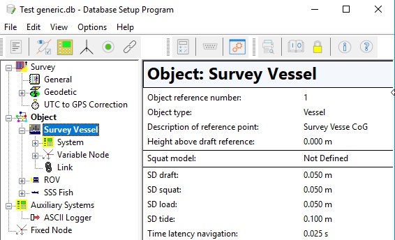
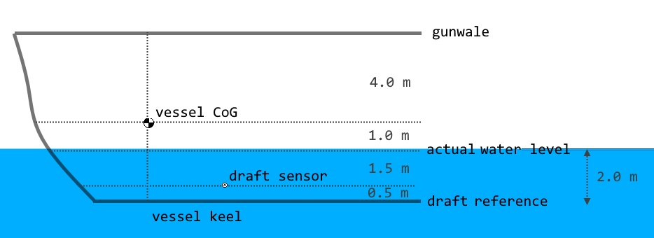
Vessel Draft | Within the latest version of Qinsy the value will be the actual water level above draft reference. Notes:
Note that this value is not available when layout is for Export. | double | ||||||||||||||||||||||||||||||||||
Computation Name | Name of the selected computation, as defined by the user in the Controller's Computation Setup. | text | ||||||||||||||||||||||||||||||||||
Computation Id | Id of the selected computation, as given by the Controller's Computation Setup. | int | ||||||||||||||||||||||||||||||||||
Time | Time of the node result. | time | ||||||||||||||||||||||||||||||||||
Easting Northing | Easting and Northing are always on Survey Datum (also known as Horizontal Datum). | double | ||||||||||||||||||||||||||||||||||
Latitude Longitude | Latitude and Longitude are default on Survey Datum (or Horizontal Datum) but the 2nd datum may also be selected if available in the Geodetic Configuration.
| geo | ||||||||||||||||||||||||||||||||||
Height | Height is by default on Chart Datum (also known as Vertical Datum) but other datums can also be selected.
| double | ||||||||||||||||||||||||||||||||||
Height Priority | Name of the heave or bathy sensor that is used for the height aided observation. The priority of these sensors is defined in the Computation Setup Object Height Priority list. Note that this value is not available when layout is for Export. | text | ||||||||||||||||||||||||||||||||||
Chart Datum Height | The difference between Chart Datum (Vertical Datum) and the selection from the Datum Property. Formula is as follows: E.g. select property Survey Datum if you want to know how much your chart datum is above/below your survey datum.
Of course, if you select property Chart Datum, the outcome will always be zero | double | ||||||||||||||||||||||||||||||||||
Age | The difference between the triggering time and the time of the node result (see above). Normally always a positive value in seconds. | double | ||||||||||||||||||||||||||||||||||
Status | The same text string as seen in the Node QC Display. | text | ||||||||||||||||||||||||||||||||||
Solution Mode | The value should come straight from the data string, decoded by the Positioning System driver which is part of the computation. | integer | ||||||||||||||||||||||||||||||||||
SOG | The speed over ground. Note that the SOG depends on the Controller's Computation Setup, Object COG / SOG, Prediction Parameters Settings.
| double | ||||||||||||||||||||||||||||||||||
| VSP | The vertical speed for the selected node. Note that the VSP depends on the Controller's Computation Setup, Object COG / SOG, Prediction Parameters Settings.
| |||||||||||||||||||||||||||||||||||
COG | The course over ground of the object on which the node is located. Note that the COG depends on the Controller's Computation Setup, Object COG / SOG, Prediction Parameters Settings.
| double | ||||||||||||||||||||||||||||||||||
ROT | The Rate-Of-Turn for the selected node.
Note that this value is not available when layout is for Export. | double | ||||||||||||||||||||||||||||||||||
Heading | The heading of the object on which the node is located. If the object does not have a valid heading, then the (COG plus Convergence) will be displayed.
| double | ||||||||||||||||||||||||||||||||||
| Crab Angle | The crab angle is also known as the drift angle. The value is the difference between the Heading and the COG of the selected node and is always between -180° and +180°. Formula: Crab Angle = Grid Heading - COG Will be empty when the object does not have a valid heading. | double | ||||||||||||||||||||||||||||||||||
Heading Priority | Name of the heading sensor that 'delivered' the heading (gyro) observation. The priority of the heading sensors is defined in the Computation Setup Heading Priority list. | text | ||||||||||||||||||||||||||||||||||
Roll | Roll of the object of the selected node, so value will be the same for any node on that object. Rotation Convention: "Positive when heeling to starboard" Value will be zero when no valid roll observation is found in the Computations Attitude priority list | double | ||||||||||||||||||||||||||||||||||
Roll Priority | Name of the attitude system that 'delivered' the roll observation. The priority of the attitude sensors are defined in the Computation Setup Pitch-Roll Priority list. | text | ||||||||||||||||||||||||||||||||||
Pitch | Pitch of the object of the selected node, so value will be the same for any node on that object. Rotation Convention: "Positive when bow up" Value will be zero when no valid pitch observation is found in the Computations Attitude priority list | double | ||||||||||||||||||||||||||||||||||
Pitch Priority | Name of the attitude system that 'delivered' the pitch observation. The priority of the attitude sensors is defined in the Computation Setup Pitch-Roll Priority list. | text | ||||||||||||||||||||||||||||||||||
Heave | The heave of the object of the selected node plus the pitch-roll induced heave of the selected node d/t the node offsets. Rotation Convention: "Positive upwards" Note that this value is not available when layout is for Export. | double | ||||||||||||||||||||||||||||||||||
VDOP | Note that this value is not available when layout is for Export. | double | ||||||||||||||||||||||||||||||||||
HDOP | Note that this value is not available when layout is for Export. | double | ||||||||||||||||||||||||||||||||||
PDOP | Note that this value is not available when layout is for Export. | double | ||||||||||||||||||||||||||||||||||
Flag | Filter flag, a bit-wise value to indicate type of position filter results. | |||||||||||||||||||||||||||||||||||
Convergence | The meridian convergence of the projection (in degrees) for the current node location. Note that Qinsy is using the so-called Gauss-Bomford convention which is the European standard. | double | ||||||||||||||||||||||||||||||||||
TPE XY | Horizontal standard deviation (2D, 95% confidence region). Value is in survey units. | double | ||||||||||||||||||||||||||||||||||
TPE Z | Vertical standard deviation (1D, 95% confidence region). Value is in survey units. | double | ||||||||||||||||||||||||||||||||||
Axis A | The major axis of the three-dimensional error ellipse (95% confidence region), constructed from the grid co-variance matrix (easting, northing and height) Value is in survey units. | double | ||||||||||||||||||||||||||||||||||
Axis B | The second axis of the three-dimensional error ellipse (95% confidence region), constructed from the grid co-variance matrix (easting, northing and height) Value is in survey units. | double | ||||||||||||||||||||||||||||||||||
Axis C | The third axis of the three-dimensional error ellipse (95% confidence region), constructed from the grid co-variance matrix (easting, northing and height) Value is in survey units. | double | ||||||||||||||||||||||||||||||||||
Alpha | The Azimuth of the three-dimensional error ellipse (95% confidence region), constructed from the grid co-variance matrix (easting, northing and height) Value is in degrees. | double | ||||||||||||||||||||||||||||||||||
Beta | The Elevation of the three-dimensional error ellipse (95% confidence region), constructed from the grid co-variance matrix (easting, northing and height) Value is in degrees. | double | ||||||||||||||||||||||||||||||||||
| QC | Value depends on the selected Parameter Property. Qinsy always uses a least squares adjustment to calculate a node position using all connected observations involved in the computation. Each observation has an a-priory standard deviation which is:
The least squares adjustment will use these a-priory SD value in order to fill the covariance matrices.
So use this QC item to show the result for each individual element of these matrices.
| double | ||||||||||||||||||||||||||||||||||
| SVP | The value will be the interpolated / extrapolated sound velocity from the current sound velocity profile at the actual water level depth for the selected node.
| double | ||||||||||||||||||||||||||||||||||
Scale Easting Scale Northing | The projection scale factor for the current node location. Note that for most projection types the easting scale factor will be equal to the northing scale factor. The scale factor can be used to convert a true range to a grid range using the following formula: grid = true * scale factor | double | ||||||||||||||||||||||||||||||||||
Compare Name | Name of the selected 'Compare to' node, as entered in Database Setup. | text | ||||||||||||||||||||||||||||||||||
| Compare Computation Name | Name of the selected 'Compare to' computation, as defined by the user in the Controller's Computation Setup. Will be empty when the 'Compare to' node is set to [none]. | text | ||||||||||||||||||||||||||||||||||
Delta Easting | Difference in easting between the selected Node and the selected 'Compare to' node. | double | ||||||||||||||||||||||||||||||||||
Delta Northing | Difference in northing between the selected Node and the selected 'Compare to' node. | double | ||||||||||||||||||||||||||||||||||
Delta Height | Difference in height (on survey datum) between the selected Node and the selected 'Compare to' node. | double | ||||||||||||||||||||||||||||||||||
Range to Node | Grid distance between the selected Node position and the selected 'Compare to' node position. Distance will two-dimensional (horizontal) by default.
Will be empty when the 'Compare to' node is set to [none] | double | ||||||||||||||||||||||||||||||||||
Bearing to Node | Horizontal bearing between the selected Node position and the selected 'Compare to' node position. Bearing direction will be: FROM the selected Node TO the selected 'Compare to' node.
Will be empty when the 'Compare to' node is set to [none], or when both selected nodes are the same. | double | ||||||||||||||||||||||||||||||||||
| Vertical Bearing | Value will be the vertical angle from the height of the reference node to the height of the 'Compare to' node, taken into account the horizontal distance between the two nodes.. i.e angle will be positive when the height of the 'Compare to' node is higher than the reference node, and will be negative when the height of the 'Compare to' node is lower than the reference node. Value will be zero when both heights are equal. Will be empty when the 'Compare to' node is set to [none], or when both selected nodes are the same. | double | ||||||||||||||||||||||||||||||||||
Delta Heading | The smallest difference in heading between the selected Node and the selected 'Compare to' node. A -tive value means counter-clockwise, a +tive value clockwise. So the value will always be between -180 and +180°. | double | ||||||||||||||||||||||||||||||||||
Delta Roll | Difference in roll between the selected Node and the selected 'Compare to' node. A -tive value means counter-clockwise, a +tive value clockwise. | double | ||||||||||||||||||||||||||||||||||
Delta Pitch | Difference in pitch between the selected Node and the selected 'Compare to' node. A -tive value means counter-clockwise, a +tive value clockwise. | double | ||||||||||||||||||||||||||||||||||
Delta X Delta Y | Delta X (or Delta Across) or Delta Y (or Delta Along) of the selected Node and the selected 'Compare to' node.
Will be empty when the 'Compare to' node is set to [none], or when Orientation is [Mainline] and the current main line is a Point. | double | ||||||||||||||||||||||||||||||||||
Delta Z | When Orientation property is not set to Heading + Motion (3D), then it will be the same value as Delta Height. | double | ||||||||||||||||||||||||||||||||||
| Angle | This is the angle between the selected Node and the 'Compare to' node with respect to the selected orientation bearing:
Will be empty when the 'Compare to' node is set to [none]. This item can be useful e.g. to get the Feathering Angle (aka Deflection Angle) for a tail buoy on a seismic survey setup: Select for the (prime) node the tail buoy and for the Compare To node the towing vessel. Important is to set the orientation property to [Mainline]. Finally use the ANGLE180 operator. | double | ||||||||||||||||||||||||||||||||||