A list with 10 entries. The first one is always the Controller's mainline. The other 9 are the Additional mainlines. The actual mainline/additional mainline selection (POINT, LINE, ROUTE) is done in the Controller's Session Setup.
Node:
Select here the Node Position, which is required for most Line Offset item calculations.
The first entry is always [Steered Node] Note that this selection is not supported when layout is for Export.
The second entry depends on the layout purpose: [From Display] when layout is for Display. The node must be selected in the display itself, under pull-down menu item Edit, Display Node... Further note that when no computation can be selected, it will always be the one from [Priority List]
The rest of the list will show all available nodes, existing in the current selected Qinsy database (see General Layout Information about loading a Qinsy database). The vessel name will be displayed in front of the variable node names. Possible defined fixed nodes will be preceded by the label 'Fixed'.
Skew:
No Node Position for the time as calculated by the Position Filter.
Yes Skewed to the time of output/trigger time, using the current Node Position (Horizontal), Time, SOG and COG. Notice that the SOG and COG depend on the Controller's Computation Setup, Object COG / SOG - Prediction Parameters Settings. The height value is not skewed, but then again, the height component is never used for any line offset calculation.
Note that terminology 'Deskew' and 'Skew' means the same in Qinsy: they are not opposites of each other. So where-ever you read the term 'skewing' in Qinsy it means the same as if you would read 'deskewing'.
Sub Item
Description
Value Type
Comment
User-defined free text.
Text Format
Normal Text Your own free plain text
Binary Enter one or more ASCII character codes, comma or space separated, in the range between 1 and 127. For example '2' for a binary STX character, '3' for a binary ETX character, or '13, 10' for CR+LF. See tableASCII Codes for an overview of all possible characters.
New Line Same as Binary but already formatted as '13, 10' (meaning CR+LF) and without a possible Field Delimiter. A Field Delimiter may be present when your layout purpose is for Export or ASCII Logging.
text
Line Name
Name of the current mainline
text
Line Type
0 if current mainline is a POINT, 1 if current mainline is a LINE and 2 if current mainline is a ROUTE.
int
Line Description
When Parent Item Line is set to [Mainline], then this Line Description will be "Current Point", "Current Line", or "Current Route", depending on the type of the current mainline.
Otherwise it will be the user-defined description of the additional mainline, as entered by the user in the Controller Session Setup, Planning, Additional Mainlines.
text
Calculation Method
When the mainline is a ROUTE it will be the Line Offset Calculation method as selected by the user in the Controller Session Setup, Planning, Settings:
"Full Search"
"Narrow Search" Notice that the selected method will automatically fall back to "Full Search" when the selected node is not the steered node, or not located on the same object as the steered node.
Further, value will be empty when the mainline is a POINT or LINE.
text
Line Index
A number between 1 and 10, indicating the selected Line of the Parent item property.
So 1 means Parent Item is [Mainline], 2 means it is [2nd Mainline] and so on.
int
Line Bearing
Output depends on whether the current mainline is a POINT, a LINE or a ROUTE:
POINT Value will be empty, because a point does not have a line bearing
LINE When the single survey line is straight (zero radius), it is of course the same value as the SOL bearing. When the line is curved (radius <> 0), it will be the bearing at the tangential point for the current node position
ROUTE Value will be the line bearing for the active section, which depends on the current node position. Further, if the active section is curved (radius <> 0), it will be the bearing at the tangential point for the current node position
Reference Property
Grid (Default)
True
double
Node Name
Name of the selected node, as entered in Database Setup
text
Node Easting
The easting of the selected node, which is always on Survey Datum.
double
Node Northing
The northing of the selected node, which is always on Survey Datum.
double
Moving Direction
Enumeration value (-1, 0 or 1) which depends on the following scenario's:
POINT
-1: Vessel is moving towards the point.
0: Absolute speed of the selected node (SOG) is less than 0.05 survey units / sec
1: Vessel is moving away from the point.
LINE / ROUTE
-1: Vessel is moving opposite to the line direction
0: Absolute speed of the selected node (SOG) is less than 0.05 survey units / sec
1: Vessel is moving to the line direction
int
Moving Direction Status
Enhanced text/label representation for item Moving Direction
Output depends on the following scenario's:
POINT
"Not Moving" Speed of the selected node towards the point is less than 0.05 survey units / sec
"Moving Towards"
"Moving Away"
LINE / ROUTE
"Before SOL, Moving Forward" Current node position is before SOL, and vessel is moving towards the line.
"Before SOL, Moving Away" Current node position is before SOL, but vessel is moving away from the line
"Before SOL, Not Moving" Current node position is before SOL, but vessel is not moving or less than 0.05 survey units / second
"On the Line, Moving Forward" Current node position is on the line, and vessel is moving towards the EOL
"On the Line, Moving Backward" Current node position is on the line, but vessel is moving backwards, towards the SOL
"On the Line, Not Moving" Current node position is on the line, but vessel is not moving or less than 0.05 survey units / second
"After EOL, Moving Away" Current node position is after EOL, and vessel is still moving away from the line
"After EOL, Moving Backward" Current node position is after EOL, but the vessel is moving back, towards the line
"After EOL, Not Moving" Current node position is after EOL, but the vessel is not moving or less than 0.05 survey units / second
text
Distance Across
POINT The closest perpendicular distance of the current node position to a virtual line. This virtual line is 'drawn' through the point and the heading of the node is used for the line bearing of the virtual line.
LINE/ROUTE The closest perpendicular distance to the line. When the node position is before SOL or after EOL, then the first or last section will be virtually extended in order to calculate the Distance Across. Value will be positive when the Node Position is starboard of the line and will be negative when the Node Position is port of the line.
Value will always be grid distance.
double
Distance Along
POINT The distance along of the current node position on a virtual line. This virtual line is 'drawn' through the POINT and the heading of the node is used for the line bearing of the virtual line. So this means the mathematical distance of the current node position 'in' the virtual line, using the closest perpendicular distance to it. Value will be positive when the node position is approaching the POINT and will be negative when the node position goes away from the POINT.
LINE/ROUTE The mathematical distance of the current node position 'in' the line, using the closest perpendicular distance to the line. So if the Node Position is exactly on SOL, then the value will be zero. If the Node Position is exactly on EOL, then the value will be equal to the total length of the line. When the Node Position is before SOL or after EOL, than the first or last section will be virtually extended in order to calculate the Distance Along. Value will be positive when the Node Position is after SOL and will be negative when the Node Position is before SOL.
Value will always be grid distance.
double
Distance Remain
Value will be the along distance of the current node position to the end of line / route.
Value will be positive when the node position is before EOL and will be negative when the node position is after EOL.
Value will always be grid distance.
double
KP
Normally Kilometer Point values represent the mathematical inline distance in kilometers. However, with the Line Tools in the Survey Manager you may set for each section user-defined KP values which in that case the KP value will be interpolated.
The value will be True KP when your Global Settings Distance Reference is set to True Range or will be Grid KP when your Global Settings Distance Reference is set to Grid Range.
Further use the Parameter property to set for which position the KP value will be represented:
Default the parameter property is set to 'Node' which means that the value will be the KP for the current node position with the closest Distance Across to the line. Change it in case you need to KP value for the start or end of the current section.
Parameter Property
Nr Format Property
Node (Default) KP value for the current node position with the closest distance across to the line
SOS KP value for the co-ordinate of the Start Of current Section. Will be empty when the current node position is before SOL.
EOS KP value for the co-ordinate of the End Of current Section. Will be empty when the current node position is after EOL.
Note the special property:
Station+Offset (US notation) This will format a KP value as a Station + Offset (which is a common notation in the USA), where Station is the KP value in survey units / 100 and the Offset the remainder (in survey units). Examples: - MP 2345.6 feet along a route will become 23+46. - KP 1.234 (equals MP 1234.0) will become 12+34. Further, the plus sign will be a negative sign when the KP is negative.
Value will be empty when the current mainline is a POINT.
double
MP
The Meter Point value for the current node position and will be the same value as the KP * 1000.
When the KP for a Route, or MP for a Line, as defined in the Survey Manager, represents the mathematical distance, then the MP value will be the same as the Distance Along value.
The value will be True MP when your Global Settings Distance Reference is set to True Range or will be Grid MP when your Global Settings Distance Reference is set to Grid Range.
double
Bearing To Sail
Output depends on whether the current mainline is a POINT, a LINE or a ROUTE:
POINT Value is always the bearing from selected node position to the point co-ordinates, regardless the heading of the selected node.
LINE / ROUTE Value depends on the following scenario's: If the Node Position is before SOL, you will get the bearing from the Node to the SOL. If the Node Position is on the line, you will get the bearing from the Node to EOL. If the Node Position is after EOL, you will get the bearing from the Node to SOL.
Reference Property
Grid (Default) The bearing as calculated using E/N (grid) co-ordinates.
True The grid bearing plus the grid convergence.
double
Bearing Next Section
Output depends on whether the current mainline is a POINT, a LINE or a ROUTE:
POINT / LINE Value is always empty.
ROUTE Value depends on the following scenario's: If the Node Position is before SOL or on the first section, you will get the SOL bearing of the 2nd section. If the Node Position is on the line, you will get the SOL bearing of the next section. If the Node Position is on the last section, you will get the EOL bearing of the current (last) section. If the Node Position is after EOL, the value will be empty.
Note: In order to get the bearing of the current section, use item Line Bearing, as explained above.
Reference Property
Grid (Default) The bearing as calculated using E/N (grid) co-ordinates.
True The grid bearing plus the grid convergence.
double
Distance To Point
Output depends on whether the current mainline is a POINT, a LINE or a ROUTE:
POINT Value will be the horizontal distance between the selected Node Position and the point co-ordinates. (It is the same value as item 'Distance to SOL / EOL', see below).
LINE / ROUTE Value will be empty!
Reference Property
Grid (Default) The distance as calculated using E/N (grid) co-ordinates.
True The distance over the sphere.
double
Distance To SOL
Output depends on whether the current mainline is a POINT, a LINE or a ROUTE:
POINT Value will be the horizontal distance between the selected Node Position and the point co-ordinates. (It is the same value as item 'Distance to Point', see above).
LINE / ROUTE Value will be the straight horizontal distance between the selected Node Position and the SOL (Start of Line) co-ordinates.
Reference Property
Grid (Default) The distance as calculated using E/N (grid) co-ordinates.
True The distance over the sphere.
double
Distance To EOL
Output depends on whether the current mainline is a POINT, a LINE or a ROUTE:
POINT Value will be the horizontal distance between the selected Node Position and the point co-ordinates. (It is the same value as item 'Distance to Point', see above).
LINE / ROUTE Value will be the straight horizontal distance between the selected Node Position and the EOL (End of Line) co-ordinates.
Reference Property
Grid (Default) The distance as calculated using E/N (grid) co-ordinates.
True The distance over the sphere.
double
Distance To SOS
Output depends on whether the current mainline is a POINT, a LINE or a ROUTE:
POINT Value will be the horizontal distance between the selected Node Position and the point co-ordinates. (It is the same value as item 'Distance to Point', or 'Distance to SOL', see above).
LINE / ROUTE Value will be the straight horizontal distance between the selected Node Position and the current SOS (Start of Section) co-ordinates. Note that for a LINE, the SOS is the same as SOL, because a LINE has only 1 section.
Reference Property
Grid (Default) The distance as calculated using E/N (grid) co-ordinates.
True The distance over the sphere.
double
Distance To EOS
Output depends on whether the current mainline is a POINT, a LINE or a ROUTE:
POINT Value will be the horizontal distance between the selected Node Position and the point co-ordinates. (It is the same value as item 'Distance to Point', or 'Distance to EOL', see above).
LINE / ROUTE Value will be the straight horizontal distance between the selected Node Position and the current EOS (End of Section) co-ordinates. Note that for a LINE, the EOS is the same as EOL, because a LINE has only 1 section.
Reference Property
Grid (Default) The distance as calculated using E/N (grid) co-ordinates.
True The distance over the sphere.
double
Current Section
Index (non-zero-based) of the closest section for the current node position.
Always 0 when the mainline is a POINT, and always 1 when the mainline is a LINE.
If the current node position is before SOL for a ROUTE, it will be 1 and if the current node position is after EOL for a ROUTE, it will be the index of the last section (same as 'Section Count', see below)
int
Section Count
Maximum number of sections of the current mainline.
Always 0 when the mainline is a POINT, and always 1 when the mainline is a LINE.
int
Section Height
Value depends on the selected parameter property and will be derived from the height value for the current POINT, LINE or ROUTE.
(These coordinate height values should be defined in your line data file (qgfline) using the Survey Manager under Edit Line data. Of course: a POINT has one height value, a LINE has two height values and a ROUTE has a height value for each waypoint)
Parameter Property
Node (default) The interpolated value for the current node location between the height value for the start and end of the current section.
SOS The exact height value for the start of the current section as defined in the line data file
EOS The exact height value for the end of the current section as defined in the line data file
When the current mainline is a POINT than the height value will always be the exact value as defined in the line data file regardless of the parameter property.
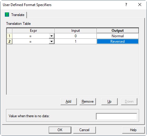
Reverse Status
Value will be 0 or 1.
0 means the current line bearing is as planned and 1 means that the current line bearing has been reversed (e.g. due to user-action Reverse Line, F7 in the Controller.
Value is always 0 in case the current mainline is a POINT.
Use the Translation property to change the value 0 and 1 into 'readable' text.
For example:
int
Speed Along
The Speed Along is calculated using the selected Node Position, SOG and COG as input parameters.
Note that the SOG and COG depend on the Computation Setup COG / SOG / Kalman Filter Settings.
When the current mainline is a POINT then this value will be the speed towards the point and is calculated as follows:
First the difference (delta angle) between direction to point (Bearing To Sail) and current sailing direction (COG) is determined. Formula: Speed Along = COS (delta angle) * SOG.
Unit Property
Meters / Second (default)
Knots Nautical miles per hour (1 NM equals 1852.0 meters)
Feet / Second International feet per second (1 foot equals 0.3048 meter)
Kilometers / Hour
Miles / Hour International (or Land) miles per hour (1 mile equals 1609.344 meters)
Value will be empty when the selected node is a Fixed Node.
double
Speed Across
The Speed Across is calculated using the selected Node Position, SOG and COG as input parameters.
Note that the SOG and COG depend on the Computation Setup COG / SOG / Kalman Filter Settings.
When the current mainline is a POINT then this value will be the speed perpendicular towards the point and is calculated as follows:
First the difference (delta angle) between direction to point (Bearing To Sail) and current sailing direction (COG) is determined. Formula: Speed Across = SIN (delta angle) * SOG.
Unit Property
Meters / Second (default)
Knots Nautical miles per hour (1 NM equals 1852.0 meters)
Feet / Second International feet per second (1 foot equals 0.3048 meter)
Kilometers / Hour
Miles / Hour International (or Land) miles per hour (1 mile equals 1609.344 meters)
Value will be empty when the selected node is a Fixed Node.
double
Time To Go
The Time To Go (TtG) is calculated using the selected Node Position, SOG and COG as input parameters.
Note that the SOG and COG depend on the Computation Setup COG / SOG / Kalman Filter Settings.
Output depends on the selected parameter property and whether the current mainline is a POINT, a LINE or a ROUTE:
POINT First the speed along is determined (see item above) and the distance to the point (Distance To Point). Formula: TtG = (distance to point) / (speed along) Notice that the TtG will be zero when the node position is moving away from the point, i.e. the speed along is negative. Further, the selected parameter has no effect when the mainline is a POINT
LINE / ROUTE First the speed along is determined (see item above) and whether the current node position is before SOL, on the line, or after EOL. TtG can be the time to go to SOL, the next section, to EOL or can be zero.
The formula depends on the following scenarios and selected parameter:
Parameter SOL
Time to Go to the start of the line / route
Given position is before start of line / route:
Vessel is moving towards the start of the line: TtG = (straight distance to SOL) / (speed along)
Vessel is moving away from the start of the line: TtG = 0 (zero)
Given position is on the line / route:
Vessel is moving towards the EOL: TtG = 0 (zero)
Vessel is moving backwards, towards the SOL TtG = (along distance to SOL) / (speed along)
Given position is after end of line / route:
Vessel is still moving away from the line: TtG = 0 (zero)
Vessel is moving back, towards the line: TtG = (straight distance to SOL) / (speed along)
Parameter EOS
Time to Go to the next section
Given position is before start of line / route:
Vessel is moving towards the start of the line: TtG = (straight distance to SOL) / (speed along)
Vessel is moving away from the start of the line: TtG = 0 (zero)
Given position is on the line / route:
Vessel is moving towards the EOL: TtG = (along distance to the next section) / (speed along)
Vessel is moving backwards, towards the SOL TtG = (along distance to SOS) / (speed along)
Given position is after end of line / route:
Vessel is still moving away from the line: TtG = 0 (zero)
Vessel is moving back, towards the line: TtG = (straight distance to EOL) / (speed along)
Parameter EOL (Default)
Time to Go to the end of the line / route
Given position is before start of line / route:
Vessel is moving towards the start of the line: TtG = (straight distance to SOL + length of the route) / (speed along)
Vessel is moving away from the start of the line: TtG = 0 (zero)
Given position is on the line / route:
Vessel is moving towards the EOL: TtG = (along distance to EOL) / (speed along)
Vessel is moving backwards, towards the SOL TtG = (along distance to SOL) / (speed along)
Given position is after end of line / route:
Vessel is still moving away from the line: TtG = 0 (zero)
Vessel is moving back, towards the line: TtG = (straight distance to SOL) / (speed along)
Value will be empty when the selected node is a Fixed Node.
timespan
Time of Arrival
The estimated time of arrival for the selected node position.
The time of arrival is actually the last update time of the selected node plus the Time to Go (TtG) so the output depends on the same scenarios as described above for the Time To Go.
Value depends also on the selected parameter property (as explained in the Time to Go item above) and value will also be empty when the selected node is a Fixed Node.
Parameter Property
SOL Time of Arrival for the start of the line / route
EOS Time of Arrival for the next section
EOL (Default) Time of Arrival for the end of the line / route
Note about Time Zone: Select [ Local Time ] if you need to support 'exotic' time zones. An exotic or non-standard time zone is e.g. Kathmandu +5.45hr.
time
Steering Direction
If current node position is starboard of the line (or point), steering direction will be character 'L'. If current node position is port of the line (or point), steering direction will be character 'R'.
Notice that starboard of the line means a positive distance across value, port of the line means a negative distance across. Further, if the current node position is exactly on the line (distance across is zero), than the steering direction character will be empty
char
Inside Area
Enumerated value 0 or 1 which depends on the selected mainline.
1 when the selected node position is inside an area / route (Note that a route is 'closed' automatically to determine whether being inside or outside)
0 when the selected node position is outside an area / route
Empty value when selected mainline is a point or line, or the selected node is not valid
int
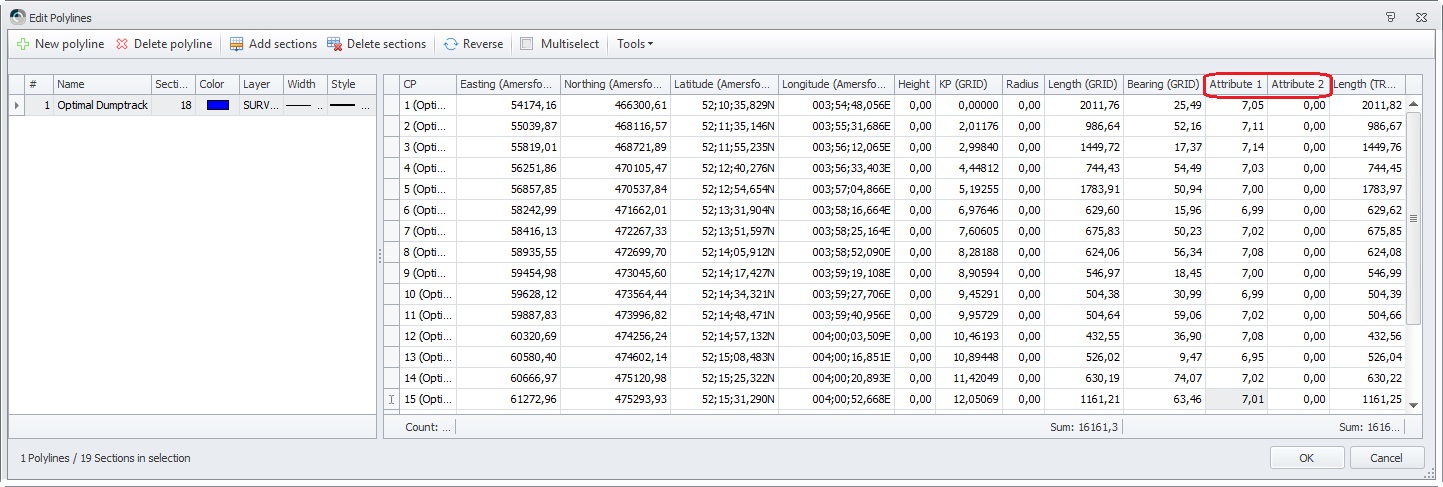
Attribute1
This will be the attribute1 value of a POINT or LINE, or the current section of a ROUTE.
With the Survey Manager you may define two additional fields next to the co-ordinate values for a POINT, LINE or ROUTE section: Attribute1 and Attribute2. It depends on your survey application whether a user needs this extra information, e.g. vertical seismic surveys, or particular dredging operations.
When the selected mainline is a:
POINT The value will always be visible
LINE The value will be empty when the selected Node position is before SOL or after EOL.
ROUTE The value is taken from the closest section, but will be empty when the selected Node position is before the first section or after the last section.
double
Attribute2
This will be the attribute2 value of a POINT or LINE, or the current section of a ROUTE.
When the selected mainline is a:
POINT The value will always be visible
LINE The value will be empty when the selected Node position is before SOL or after EOL.
ROUTE The value is taken from the closest section, but will be empty when the selected Node position is before the first section or after the last section.
double
JavaScript errors detected
Please note, these errors can depend on your browser setup.
If this problem persists, please contact our support.