BHD Generic - Raw Data Items

Selecting Raw Data Items

These are the items under Raw Data.

Observation Systems

Refer to for more information on Observation System parameters.

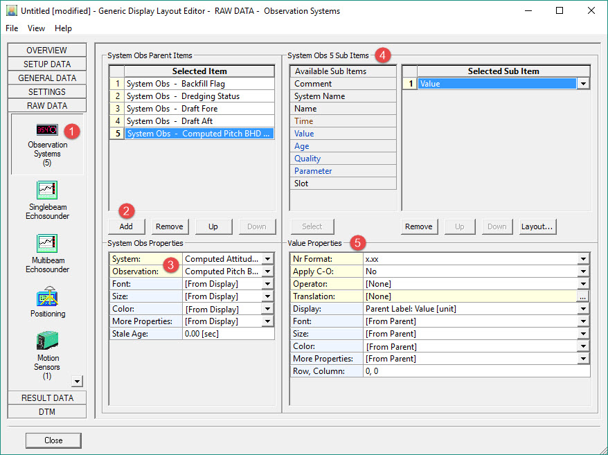
image2016-3-9 10:9:12.png Click on Raw Data and then Observations Systems.

BHD_GenDsp_RawData_ObsSys.jpg

image2016-3-8 11:17:51.png Click on AddButton.jpg .

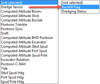
image2016-3-9 10:14:57.png Select a System and an associated Observation.These are the Observation Systems supported:

    • Gyro Compass

    • Underwater Sensor

    • Speed Log

    • Tide Gauge

    • Surface Navigation Systems

    • Magnetometer

    • Miscellaneous Systems

    • Dredging Sensor

    • Rotation Angle Sensor

    • Acceleration Velocity Sensor

Add Backfill Flag and Dredging Status from these choices in our example:
BHD_GenDsp_RawData_DredgeSensorObs.jpg

image2016-3-14 17:26:22.png Select which Sub Items to show for each observation. In our example only the Value is added.

image2016-3-14 17:40:52.png Set the Properties for each sub-item.

image2016-3-14 17:41:3.png Click on  AddButton.jpg multiple times to add the Observation Systems and Observations shown below. For each add the Sub Item 'Value'.

BHD_GenDsp_RawData_ObsSys_ValueProps.jpg

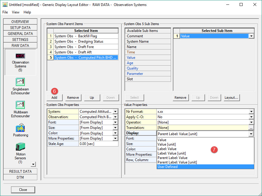
image2016-3-14 17:41:15.png Highlight for example, the Computed Pitch, Sub Item 'Value'.

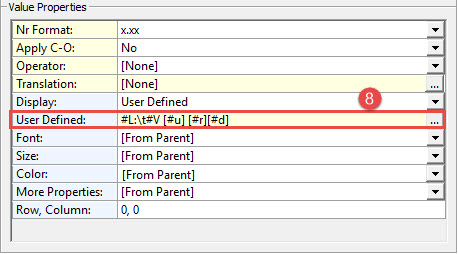
Click on the Display drop down arrow and select User Defined. This changes the options under Properties by adding a line.
BHD_GenDsp_RawData_ValueProps_UserDefined.jpg

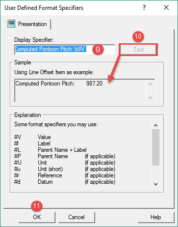
image2016-3-14 17:41:26.png Click on the browse button BHD_GenDsp_BrowseButtonIcon.jpg  to open the User Defined Format Specifier dialog.

BHD_GenDsp_UserDefinedFormatSpecifiers.jpg

image2016-3-14 17:41:39.png Modify the Display Specifier as shown above. 

image2016-3-14 17:41:50.png Click on BHD_GenDsp_TestButtonIcon.jpg  to check what will be finally displayed is what you want.

image2016-3-14 18:9:34.png Click OK.

Refer to for more information on format specifiers.
Refer to for an explanation of operators acting on data values.

Return to: top of page.

Singlebeam Echosounder

No singlebeam echosounder is defined in our example.
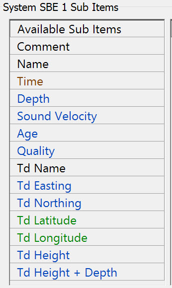
These are the Sub Items:
Dredging_GenericDsp_RawSBEsubItems.jpg

Refer to for more information

Return to: top of page.

Multibeam Echosounder

List with all available multibeam and multi-transducer echosounder systems that exist in the current selected QINSy database.
Because different types of multibeam echosounder systems are supported (Ro/Theta, X/Y/Z, Profilers) and multi-transducer systems, some items below may not be applicable for the particular type.

No multibeam echosounder is defined in our example.
These are the Sub Items:
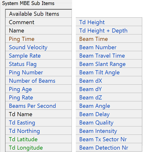
Dredging_GenericDsp_RawMBEsubItems.jpg

Refer to for more information.

Return to: top of page.

Positioning

Display of spud pole and dredge tool positions are to be added; however, positioning here refers to raw data and results data is preferred.
These are the raw data sub-items:
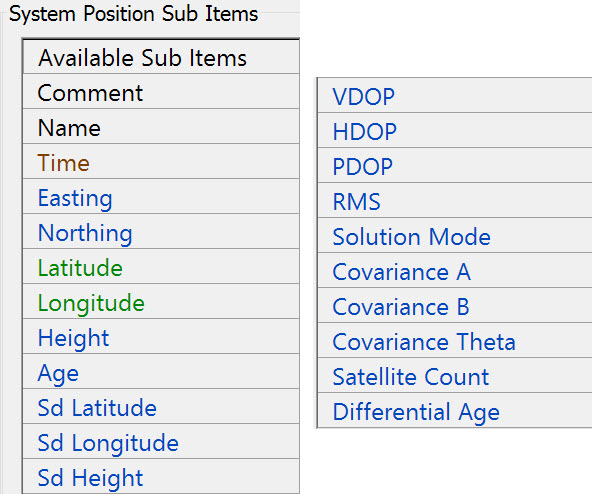
Dredging_GenericDsp_RawPositionSubItems.jpg

Refer to for more information.

Return to: top of page.

Motion Sensors

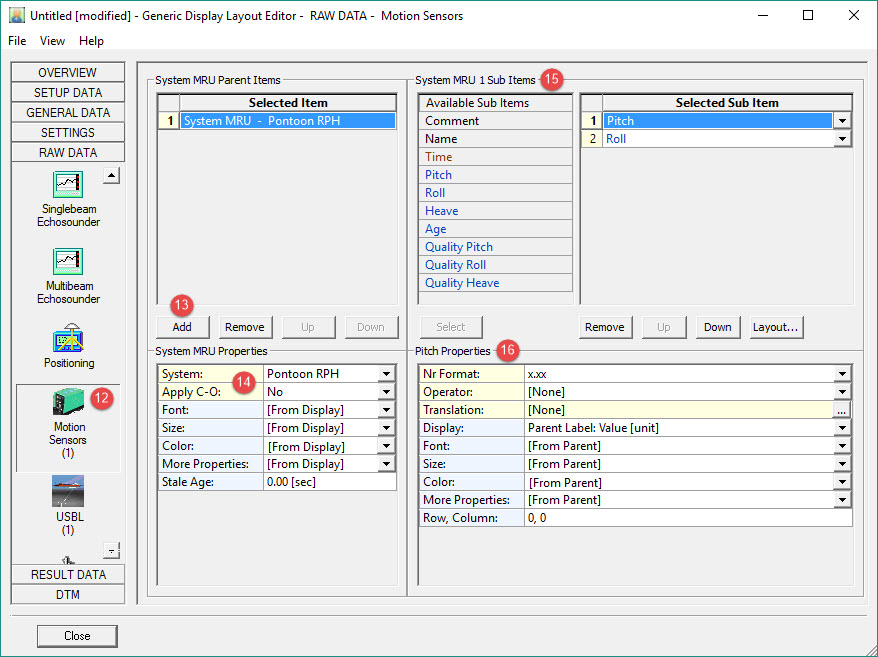
image2016-3-14 18:9:45.png Click on Raw Data and then on Motion Sensors.

BHD_GenDsp_RawData_MRU.jpg

image2016-3-14 18:10:1.png Click on AddButton.jpg .

image2016-3-14 18:10:15.png Select the System and decide whether to apply the C-O value.

image2016-3-15 14:23:1.png Double click on the Sub Item 'Pitch'.

image2016-3-15 14:23:20.png Modify Pitch Properties if necessary.

Refer to for explanations of the various properties.

Refer to for more information.

Return to: top of page.

USBL

QINSy may be receiving positions of spud and/or bucket in the form of pseudo USBL measurements, i.e. a dX/dY/dZ measurement from the dredger's reference point to the spud and/or bucket. Displaying these measurement may be useful, especially the range to the spud pole.

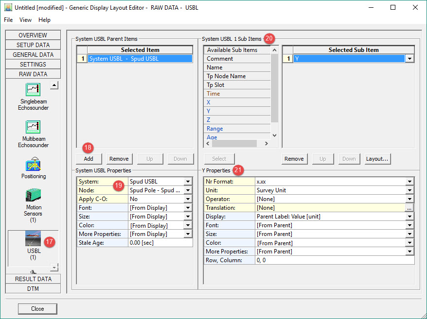
image2016-3-15 14:59:24.png Click on Raw Data and then on USBL (in dredging usually a pseudo-USBL system).

BHD_GenDsp_RawData_USBL.jpg

image2016-3-15 14:59:37.png Click on AddButton.jpg .

image2016-3-15 14:59:50.png Select the USBL System and the target Node.

image2016-3-15 15:0:1.png Select the associated Sub Items.

In this case only the 'Y' value which provides the range to the spud pole as it slides forward and backward.

image2016-3-15 15:0:16.png Modify the Properties if necessary.

Refer to for explanations of the various properties.

Refer to for further explanation.

Return to: top of page.

Layback

No Layback system is defined in our example.
These are the sub-items:
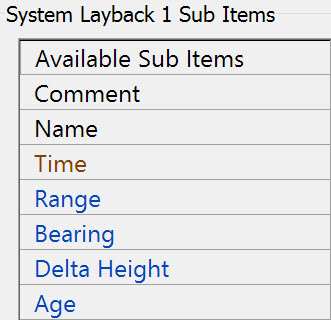
Dredging_GenericDsp_RawData_LaybackSubItems.jpg

Refer to  for more information.

Return to: top of page.

Return to: BHD - Generic Display.