
Analog Display
The Analog Display is used to display an observation in a meter or a gauge type format.
For example, to display the object pitch and roll, or to display dredging production parameters such as mixture velocity, density, and volume.
|
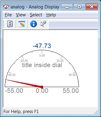
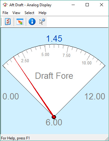
An analog 'Meter' display could look like this: |
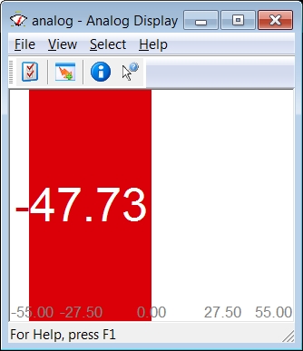
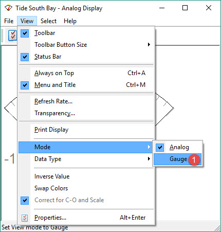
The corresponding 'Gauge' could look like this: |
|
|
|
You may or may not find this display useful but it is presented in the event you find a good application.
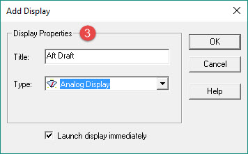
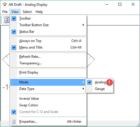
Take the following steps to create an Analog Display:


Two types of meters can be displayed; both are presented in the form of examples.
Return to: top of display.
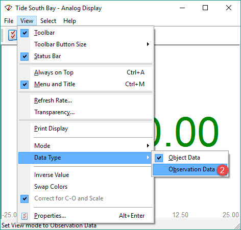
Analog - Observation
This example is an analog observation that displays Draft.
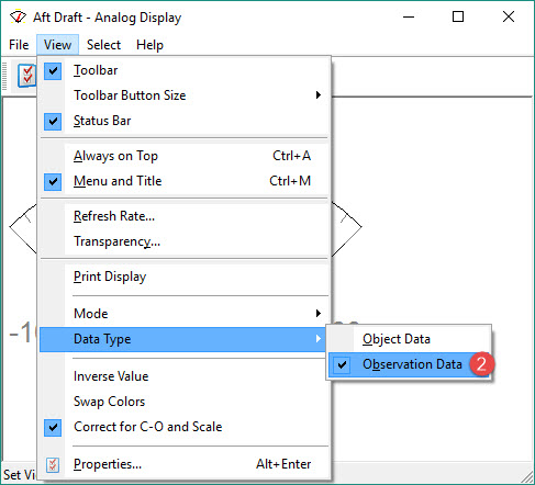
When “Observation Data” is selected, there is an option in the View menu to correct for C-Os and scale.
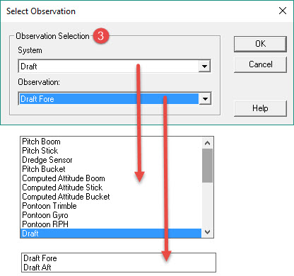
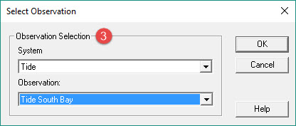
Select a Draft system and the Draft Fore observation. Pressing OK returns to the Analog Display itself.

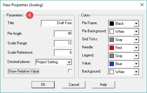
Enter parameter values and make parameter selections.

Return to: top of display.
Gauge - Observation
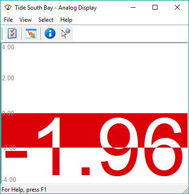
This example is a gauge to display the tide.
When “Object Data” is selected, calculated results of the steered node are displayed.
Make parameter selections as above:
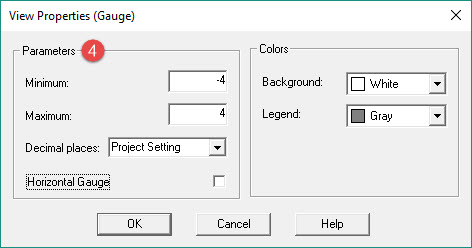
Enter parameter values and make parameter selections as follows:
|
Parameters |
|
|---|---|
|
Minimum/Maximum |
Set the minimum and maximum values for the bar. |
|
Decimal places |
Select the number of digits after decimation point. |
|
Horizontal Gauge |
When activated the gauge is displayed horizontally, when deactivated the gauge is displayed vertically. |
|
Colors |
Specify how the display should look. |
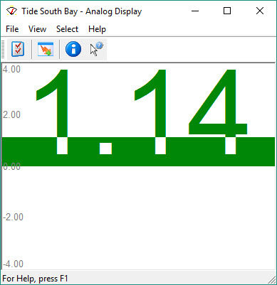
This type of display shows a tide above Vertical Datum in green and a tide below Vertical Datum in red.
Return to: top of display.
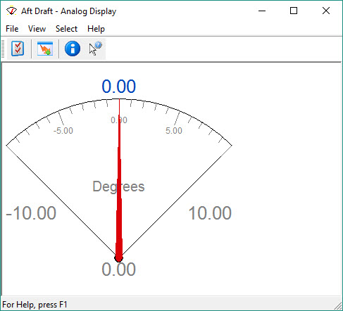
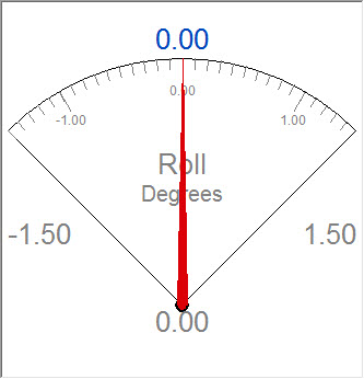
Analog - Object
This example is an analog observation that displays backhoe Roll.
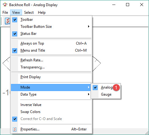
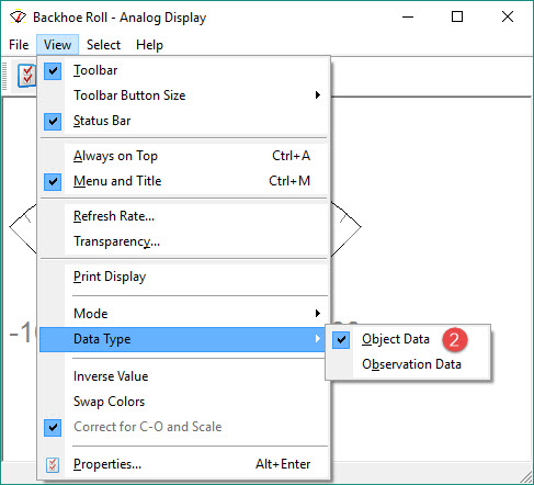
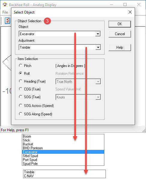
Select an Object and an Adjustment. Then select Roll.
|
Object Selection |
|
|---|---|
|
Object |
Select an available object from the pull down menu. |
|
Adjustment |
Select a computation from the pull down menu. |
|
Pitch, Roll, Heading (True)
|
Select which item is to be displayed for this object. |
|
Rotation Reference |
Choose between True North, Grid North or Project Settings. Only adjustable when Heading or Course Over Ground are selected. |
|
Speed Value Unit |
Select between Knots, km/h, m/s or Project Settings. Only adjustable when Speed Over Ground is selected. |
Pressing OK returns to the Analog Display itself.
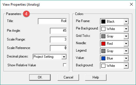
Enter parameter values and make parameter selections.
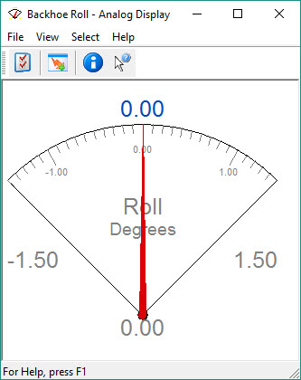
De-activate the Status Bar, the Tool Bar, and the Menu & Title to clean up the presentation.
Return to: top of display.
Return to: BHD - Online Displays.