TSHD - Analog Display

Analog Display

The Analog Display is used to display an observation in a meter or a gauge format; for example, to display the object speed along and across, or to display dredging production parameters such as mixture velocity, density, and volume.

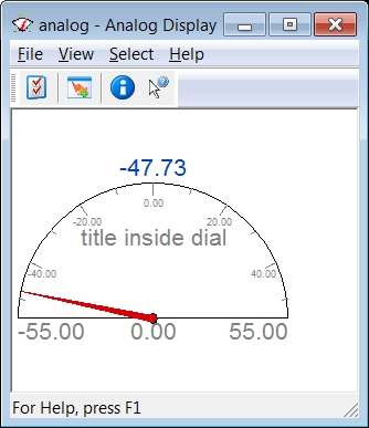
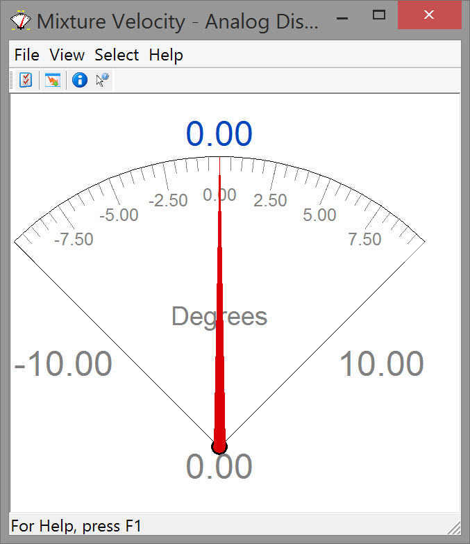
An analog 'Meter' display could look like this:

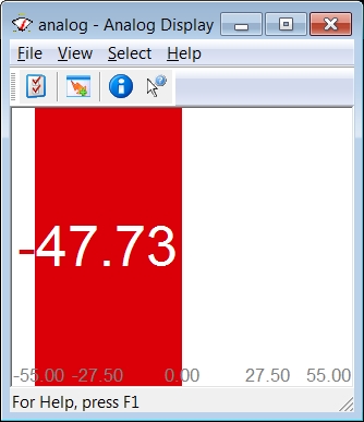
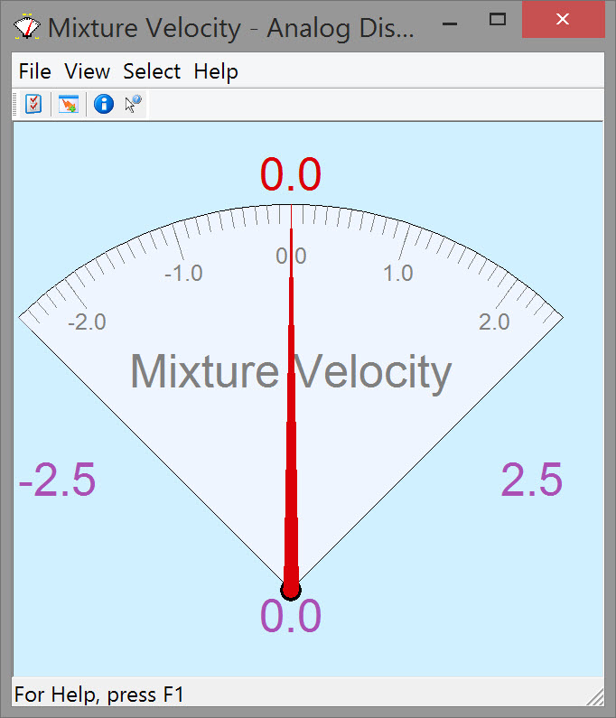
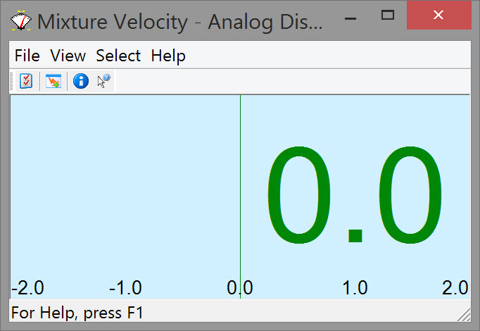
The corresponding 'Gauge' could look like this:

CtrOptionsAnalog.jpg

CtrOptionsAnalogGauge.jpg

Take the following steps to create an Analog Display:

image2016-3-8 11:5:42.png Go to “Options” on the menu bar of the Controller and select “Displays”, or click on the Displays icon Dredging_AnalogDsp_DisplaysIcon.jpg . This opens the Display Manager.

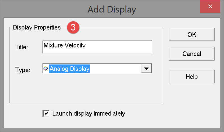
image2016-3-8 11:17:51.png Click on  AddButton.jpg to open the Add Display dialog:

Dredging_AddDisplay_AnalogMixtureVel.jpg

image2016-3-8 11:21:39.png Select type “Analog Display” and enter a title name. Pressing OK opens the Analog Display initially looking something like this:

Dredging_AnalogDsp_InitialDialog.jpg

Two types of meters can be displayed; both are presented in the form of an example.

Dredging Parameters

This example is an analog observation that displays Mixture Velocity.
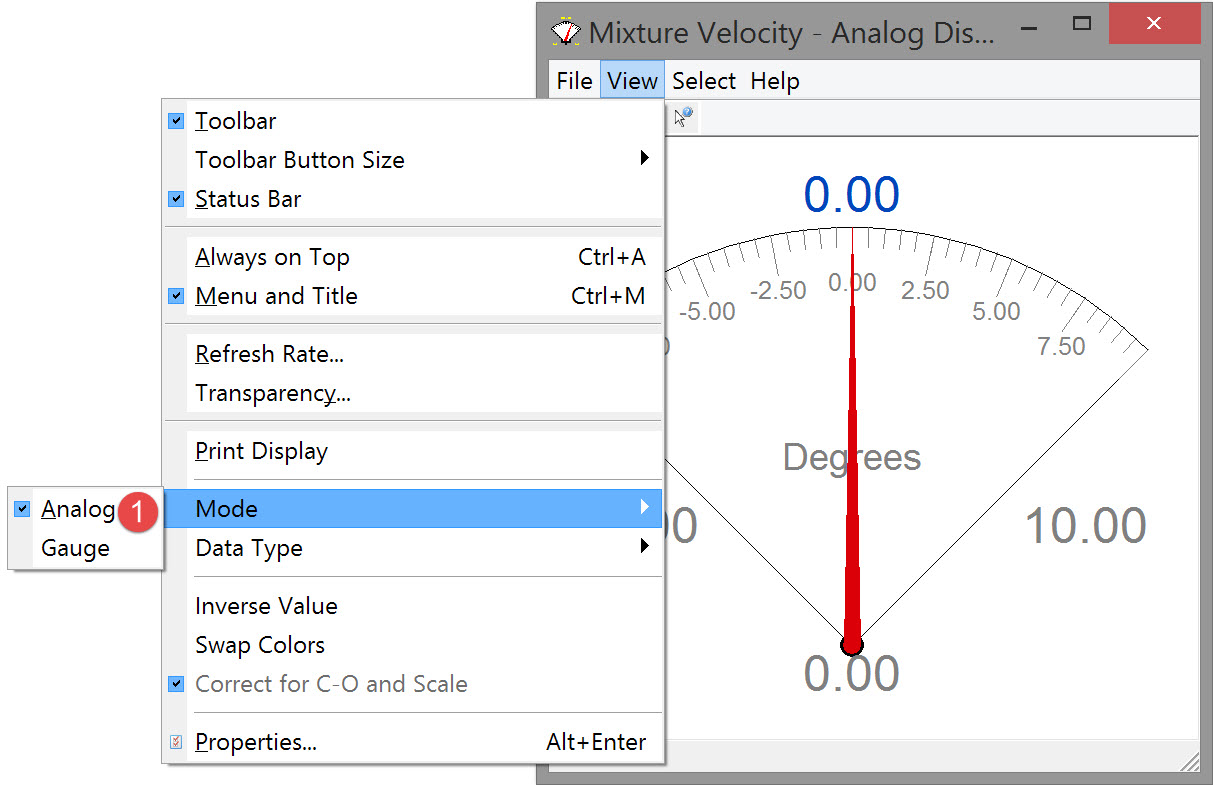
image2016-3-8 11:5:42.png Go to “View” on the menu bar and select “Mode”, and then “Analog”.

Dredging_AnalogDsp_ModeAnalog.jpg

image2016-3-8 11:17:51.png Go to “View” on the menu bar and select “Data Type” and then “Observation Data”.

When “Observation Data” is selected, there is an option in the View menu to correct for C-Os and scale.
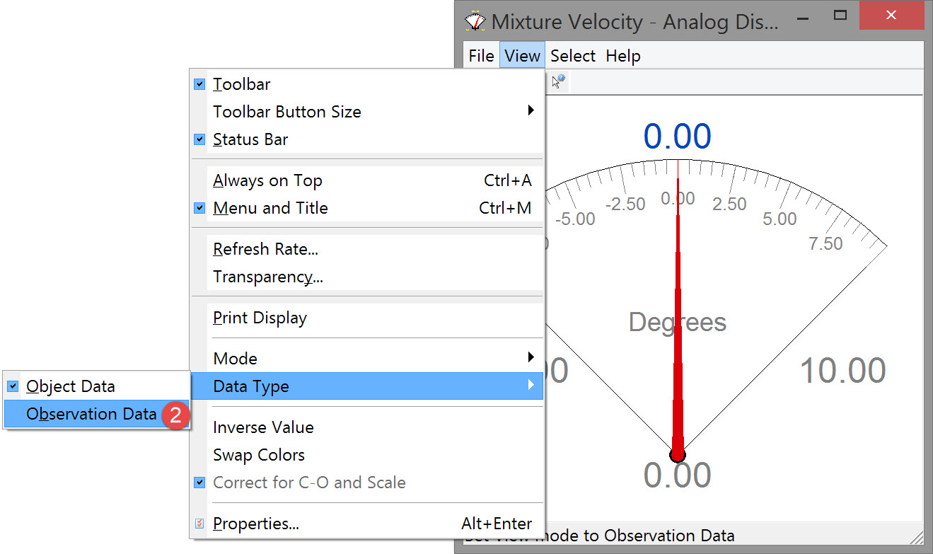
Dredging_AnalogDsp_TypeObs.jpg

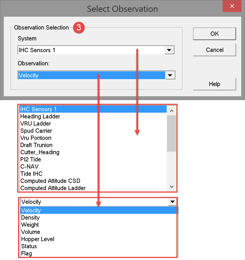
image2016-3-8 11:21:39.png Go to “Select” on the menu bar and select “Observation”, the following dialog opens:

Dredging_AnalogDsp_SelectObsVelocity.jpg

Select a Dredging Sensor system and the Velocity observation. Pressing OK returns to the Analog Display itself.

image2016-3-8 11:53:30.png Go “View” on the menu bar and select “Properties” in order to change the properties of the display.

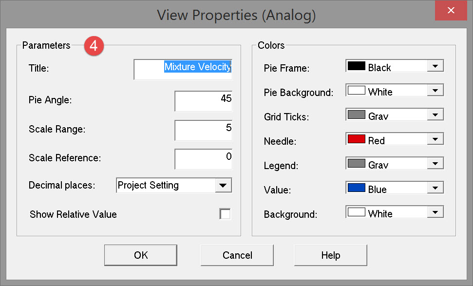
Enter parameter values and make parameter selections.
Dredging_AnalogDsp_ViewProperties.jpg

Click here for a description of each parameter...

Parameters

Title

Enter a title for the dial face.

Pie Angle

Enter how much of the dial face should be visible: 40 to 90 degrees on either side of the needle can be shown.

Scale Range

Set the “Scale Range” by entering a value that represents the difference between the minimum and maximum.
For instance when a minimum and maximum of -10 and 10 needs to be set a scale range of 20 must be entered.

Scale Reference

Scale reference is half the scale range.
Minimum and maximum values are a combination of scale reference and scale range.

Decimal places

Select the number of digits after decimation point.

Show Relative Value

When Scale Reference is not equal to zero, the reading relative to the set scale reference is displayed in brackets.
The absolute reading is displayed without brackets.

Colors

Specify how the display should look.


Dredging_AnalogDsp_FinalDialog.jpg

image2016-3-8 12:16:11.png Repeat the process to add a display for Mixture Density, Production etc..

Speed Across

This example is a gauge to display the across speed of the vessel.
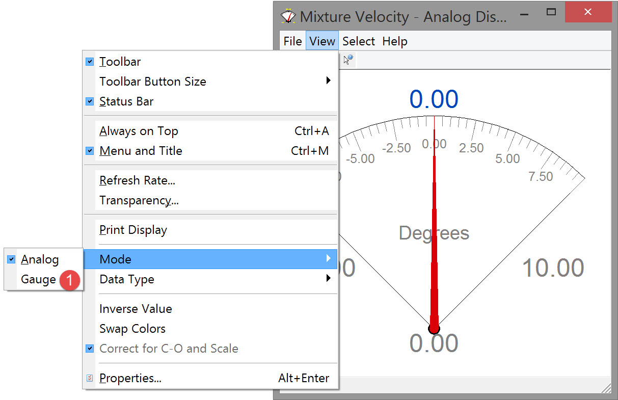
image2016-3-8 11:5:42.png Go to “View” on the menu bar and select “Mode”, and then “Gauge”.

Dredging_AnalogDsp_ModeGauge.jpg

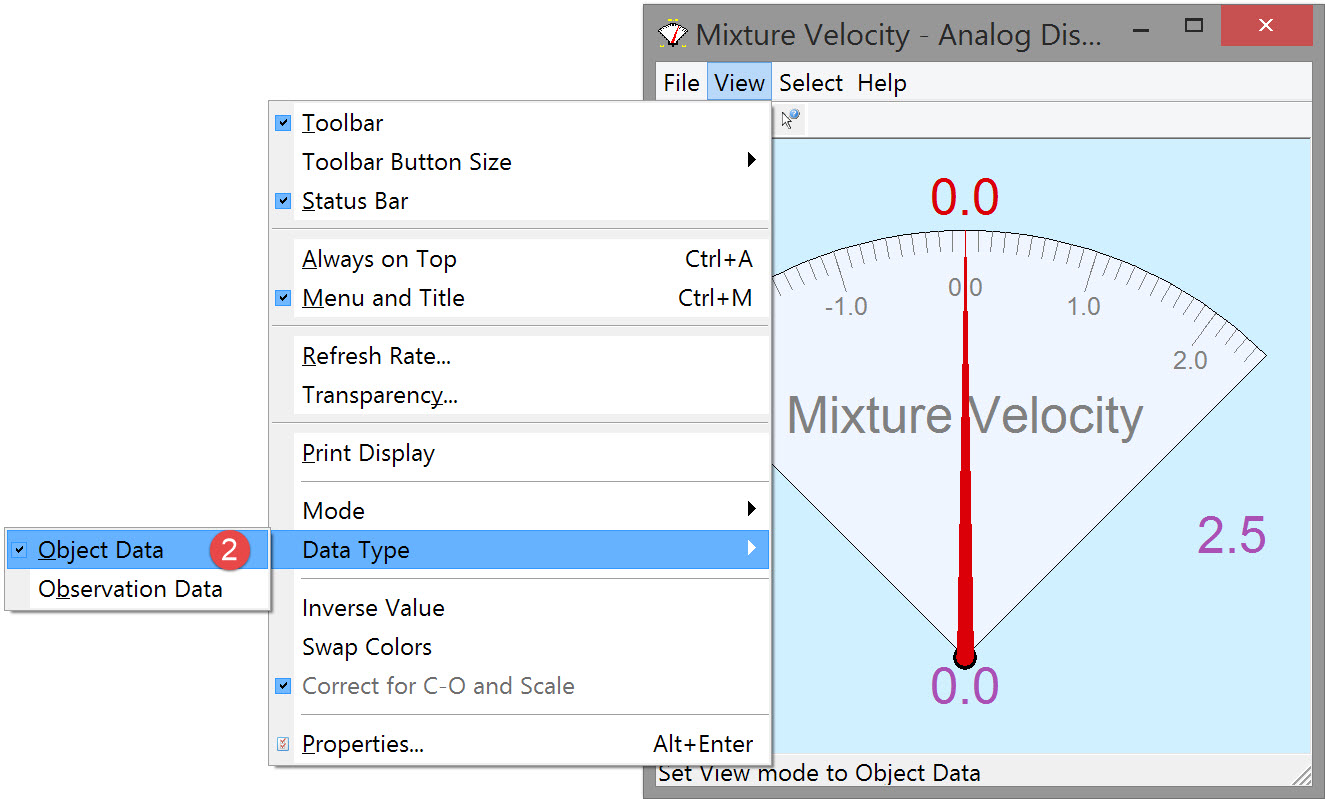
image2016-3-8 11:17:51.png Go to “View” on the menu bar and select “Data Type” and then “Object Data”.

When “Object Data” is selected, calculated results of the steered node are displayed.
Dredging_AnalogDsp_TypeObectData.jpg

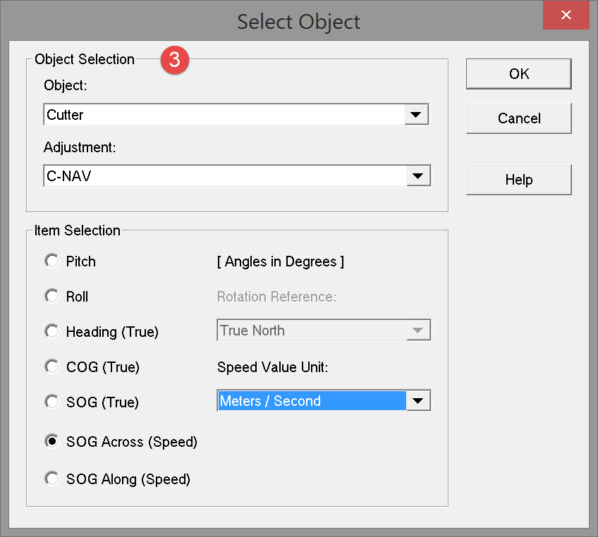
image2016-3-8 11:21:39.png Go to “Select” on the menu bar and select “Object”, the following dialog opens:

Dredging_AddDisplay_SelectObject_SpeedAcross.jpg

Make parameter selections as follows:

Object Selection

Object

Select an available object from the pull down menu.

Adjustment

Select a computation from the pull down menu.

Pitch, Roll, Heading (True)
COG (True), SOG (True)
SOG Across (Speed)
SOG Along (Speed)

Select which item is to be displayed for this object.

Rotation Reference

Choose between True North, Grid North or Project Settings. Only adjustable when Heading or Course Over Ground are selected.

Speed Value Unit

Select between Knots, km/h, m/s or Project Settings. Only adjustable when Speed Over Ground is selected.

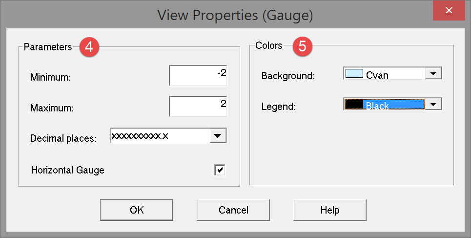
image2016-3-8 11:53:30.png Go to “View” on the menu bar and select “Properties” in order to change the properties of the display. The following dialog opens:

Dredging_AnalogDsp_ViewProperties_Gauge.jpg

Enter parameter values and make parameter selections as follows:

Parameters

Minimum/Maximum

Set the minimum and maximum values for the bar.

Decimal places

Select the number of digits after decimation point.

Horizontal Gauge

When activated the gauge is displayed horizontally, when deactivated the gauge is displayed vertically.

Colors

Specify how the display should look.

Dredging_AnalogDsp_FinalDialog_Gauge.jpg

Return to: top of display

Return to: TSHD Online Displays