
Computation Setup
All the internal calculations are defined and enabled or disabled in the Computation Setup.
Computations must be defined before a survey can begin.
Go to “Settings” on the Controller's menu bar and select “Computation Setup” in order to open the Computation Setup.
All available computations, objects, systems and sensors are shown in the object tree in the middle pane.
Expand the tree structure by selecting the plus sign in front of an object or system.
Computation Settings are not the focus of Howto Dredging.
The following is a brief outline of dredging related settings. For a more detailed explanation of computations please refer to:
-
Help pages, in particular the Computation Setup pages.
-
How-to Computation in the Knowledge Base, in particular How-to Computation Setup.
General Discussion
Computation and display possibilities are determined by what parameters are being received from the PLC and/or from direct interfacing of sensors to QINSy. In many instances dredge head positions are provided by the PLC to QINSy in the form of pseudo-USBL dX/dY/dZ values referenced to the TSHD reference point (e.g. CoG).
This makes for a simple computation setup facilitating display of dredge head locations but is more problematic in terms of being able to display upper and lower suction pipes between the dredge heads and the inlets. Displays in plan, profile and/or 3D require a lot more information in order to show pipes and drag heads realistically. Pitch and horizontal rotation angles of upper and lower pipes as well as drag heads are required.
This simulated example shows availability of probably more observations than are typically provided:
In this scenario there are some potential conflicts:
-
USBL 'Z' values versus depths provided by depth sensors on the drag head.
-
Position provided via USBL versus position provided by computing from inlet coordinates though upper and lower pipe attitude to the drag head.
In a real situation these various observation values received by QINSy would correlate since pipe length and attitude observations are used to determine pseudo-USBL observations. Any small discrepancies would be addressed through applying different observation weighting.
The point being made here is that you need more than pseudo-USBL observations to display pipes and drag heads properly. Should you be fortunate enough to receive sufficient observations to create realistic displays, you might have to modify observation weights to make the computation solve.
Dredge Head Models

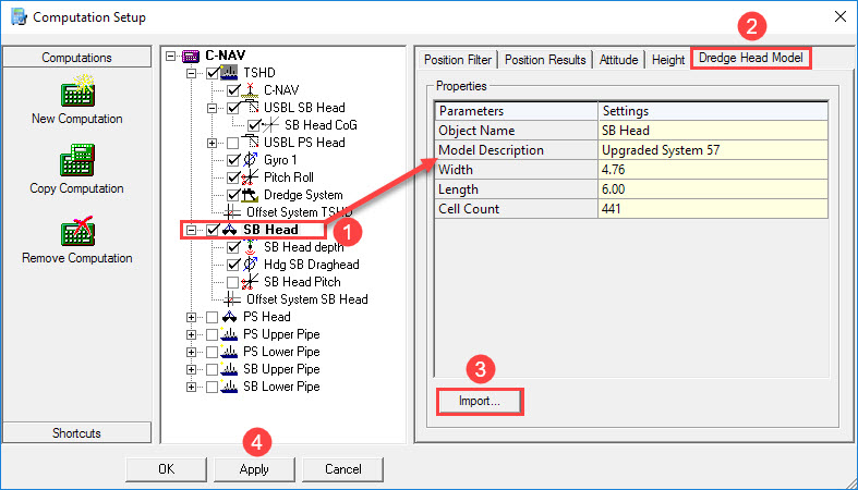


When going offline the active shape and model are stored in the template so that always the latest is available.
This functionality can be useful for hydraulic cranes that change buckets.
Please refer to How-to Dredgehead Models for further information about changing the dredging tool while Online in data acquisition mode.

Return to top of page.
Return to Trailing Suction Hopper Dredger - Online.
Typical Computation Settings
A standard computation setup for a TSHD looks something like this dialog which gives an overview of the computation(s).
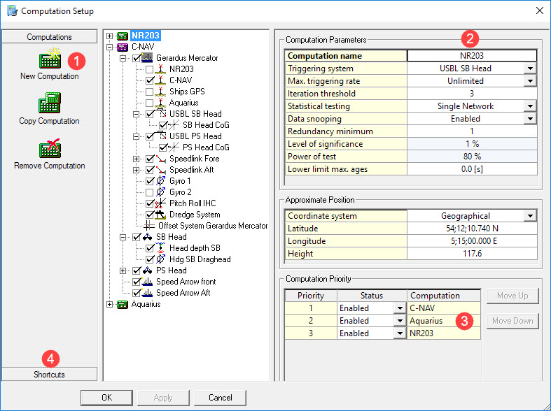
It is wise to create a computation for each available positioning system. Then, if the primary computation fails because of a failure in the positioning system, the software will automatically switch over to the secondary computation with a different positioning system selected.
Take the following steps in order to check the most common settings in the computation.


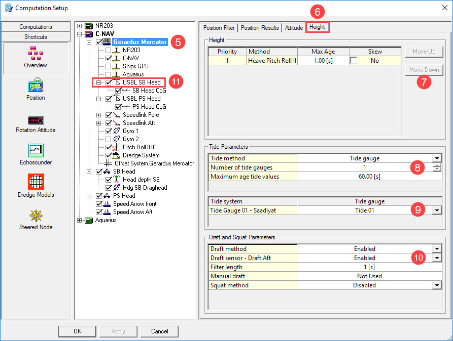


With two or more tide gauges Auto Select automatically uses the two nearest stations in the area, based on KP values along a route and the current vessel position.
If only one station is selected, the nearest is searched for continuously.
Data which is too old or which is of bad quality (QI < 0) will be ignored.


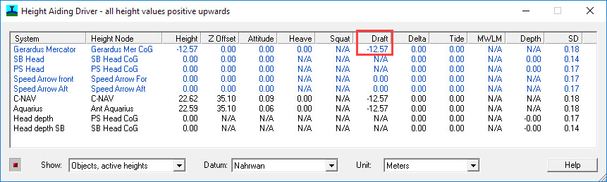
A choice between Manual draft, which can be entered here, and a Draft sensor must be made.
A list of draft sensors that can be enabled or disabled is shown. It is only possible to enable a draft sensor when it was added to the Database Setup.
If no draft sensors are defined, or all sensors are disabled, then Manual draft is used.
A Draft sensor data can be very noisy; therefore it is useful to set a filter length. Draft observations are filtered using a median filter, which takes the statistical median over all observations in the filter time period. This filter time period can be entered here as filter length in seconds, minimum filter length is 1second, maximum is 600 seconds..
The Manual Draft value to be used for the height computations. The draft value is relative to the draft reference defined in the Database Setup's 'Object Definition'.
Draft algorithm
Draft is calculated in the height aiding driver. One single draft value valid for the CoG is calculated per object. Every QINSy heartbeat update (0.25 seconds) a new draft value is calculated. The following steps are taken in the calculation process:
The Draft for time T0 is required.
-
Raw data buffer is maintained for every sensor.
-
Retrieve observations for period T0 - FilterLength to T0. (Every draft observation is already lever arm corrected for the object attitude valid for the observation time).
-
Take the median draft value from this period for every sensor.
-
For multiple sensors create an average value from the median values. This average value can now be seen as the mean draft for the object.

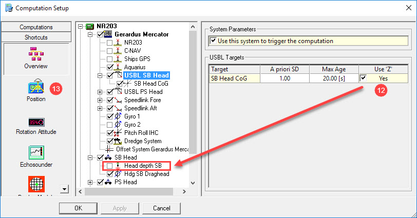

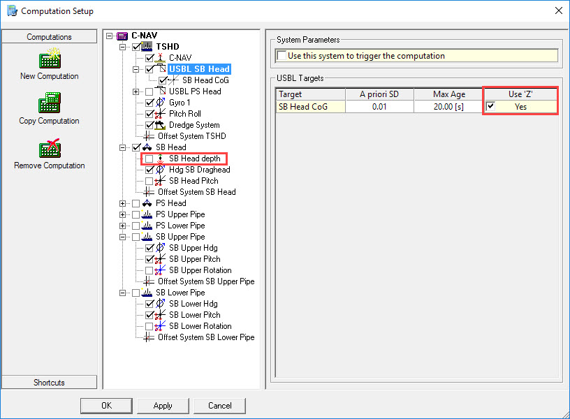
If using a depth observation for the dredging tool only the horizontal observations are required. Therefore deselect the Z observation, and enable the depth observation by selecting the tick box in the item tree.

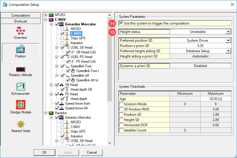


When accurate height is selected the height from the GPS receiver will be used; this will overrule all height related components such as tide and draft.
In most cases the height will be set to unreliable, and tide and draft observations will be used in order to calculate the correct height. These settings will not affect the height of the dredge head.
Return to: top of page
Return to: Trailing Suction Hopper Dredger - Online