
Computing and Displaying Production
Definitions
Tons Dry Solid (TDS) measures the hopper-load's volume and weight in order to determine the quantity of "dry solids" that it contains. By applying the values for the dry solid's specific density and the in situ water's density in a formula with the hopper-load's weight and volume (which indirectly measures the hopper-load's average density), the total quantity of the dry solids can be calculated.
The displacement or displacement tonnage of a ship is the ship's weight. The name reflects the fact that it is measured indirectly, by first calculating the volume of water displaced by the ship, and then calculating the weight of that water. By Archimedes' principle, this is also the weight of the ship.
Displacement should not be confused with other measurements of volume or capacity typically used for commercial vessels such as net tonnage, gross tonnage, or deadweight tonnage.
The process of determining a vessel's displacement begins with measuring its draft.This is accomplished by means of its "draft marks" (or "load lines"). A merchant vessel has three matching sets: one mark each on the port and starboard sides forward, midships, and astern. These marks allow a ship's displacement to be determined to an accuracy of 0.5%.
The draft observed at each set of marks is averaged to find a mean draft. The ship's hydrostatic tables show the corresponding volume displaced.
To calculate the weight of the displaced water, it is necessary to know its density. Seawater (1025 kg/m³) is more dense than fresh water (1000 kg/m³);so a ship will ride higher in salt water than in fresh. The density of water also varies with temperature.
The hopper volume of a vessel is given in the form of a so-called hopper table, or "sounding hopper table". This is the calculated volume versus the average level in the hopper. As long as the walls of the hopper are vertical the trim has no influence. On some ships, the wall at the top of the hopper is inside; this results in a (limited) error in the volume.
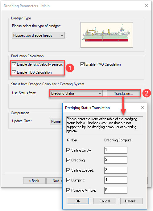
The status of the dredging cycle is determined by a PLC. This is a small computer receiving signals referencing valve positions and proximity switches etc.. The point in the dredging cycle is determined on the basis of these signals. The output is a number representing the status.
Computation of TDS
Different methods of computing TDS
-
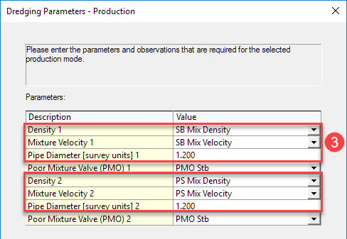
Using mixture velocity, mixture density and suction pipe diameter. Trip volume and load are computed based on these parameters.
-
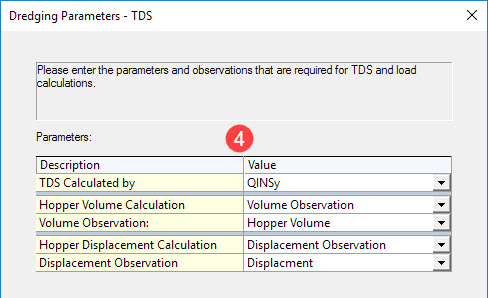
Using hopper levels, displacement and volume.
-
Hopper volume is computed using the average height of water levels in the hopper and "hopper tables".
-
Displacement is computed using draft measurements and a "displacement table". The draft of the hopper dredge is directly related to the weight of the dredge, plus loaded water and sediment. The draft can be related to vessel displacement with a draft/displacement table typically available from the shipyard. The total weight of material in the hopper is equal to the weight of bin water in the hopper before the load is taken plus the slurry load added. This total weight divided by the volume that the material occupies in the hopper is the average density of the material in the hopper.
-
The empty weight of the vessel is calculated right after dumping by subtracting from the displacement plane to dump after subtracting the weight of the water in the hopper and the trim tank.
-
QINSy does not, at time of writing (July 2016), support computation of volume and displacement. These parameter values must be read from the dredge PLC.
Database Setup - Sensor Input
In Database Setup define Dredging sensor observations including:
-
Displacement
-
Hopper volume
-
Hopper levels (multiple locations)
-
Dredging status
-
Mixture velocity (port and starboard)
-
Mixture density (port and starboard)
-
Flag (e.g. PMO status)
Also define Underwater sensor observations including:
-
Draft (draught) fore and aft
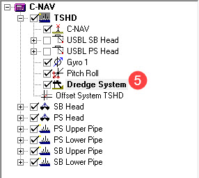
And define a Dredging System as follows:


Online
Computation Settings


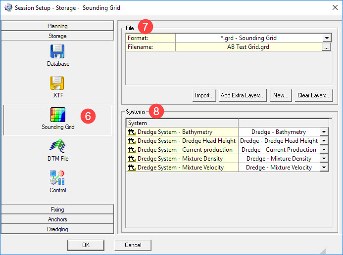


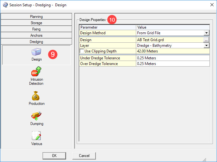

One of - From Grid File, From QGF File or From Mapping File (PRO).
The correct file and layer.
Enter - a clipping depth if appropriate and dredge tolerances.


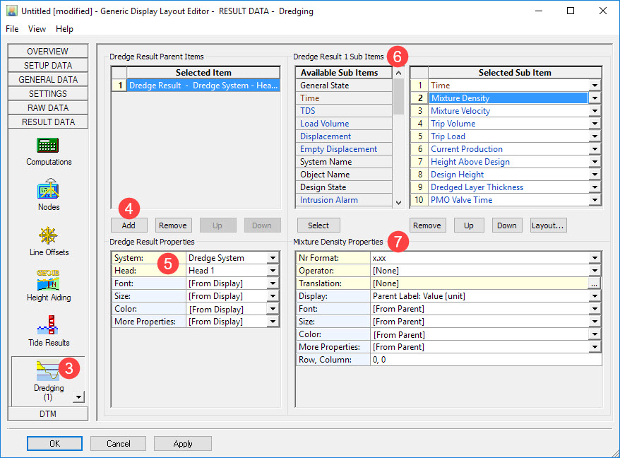
Generic Display


|
Sub Item |
Description |
|---|---|
|
General State |
|
|
Time |
Update time of the dredging driver
|
|
Design State |
|
|
Mixture Density |
Current mixture Density from production sensor, (c-o) already applied |
|
Mixture Velocity |
Current mixture velocity from production sensor, (c-o) already applied |
|
Trip Volume |
Current volume inside the selected dredging system |
|
Trip Load |
Current load inside the selected dredging system |
|
Current Production |
Current production, derived from production sensors
|
|
Height Above Design |
Actual height minus the design height at footprint of the selected head.
|
|
Design Height |
Height of design at footprint of the selected head.
|
|
Dredged Layer Thickness |
Amount of removed soil.
|
|
PMO Valve Time |
Total time that PMO (Poor Mixture Overboard) was open (Spilling overboard). |
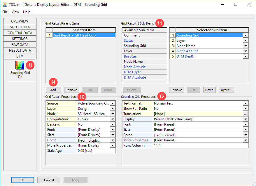
Select the grid layer to reference.
Select the node to reference, e.g the drag head reference node.
Choose the computation and whether to deskew position or not.
|
Source: |
Active Sounding Grid
[ Browse...]
|
|
Filename: |
The selected sounding grid filename. This option is only visible when the source is not the Active Sounding Grid.
|
|
Layer: |
Select the layer for retrieving the DTM Depth or other attribute values from.
|
|
Node: |
Select here the Node Position. The first entry is always [Steered Node]
The second entry depends on the layout purpose:
The rest of the list will show all available nodes, existing in the current selected QINSy database
|
|
Deskew: |
No
Yes
|

|
Sub Item |
Description |
|---|---|
|
Comment |
Normal Text
Binary
for an overview of all possible characters.
|
|
Status |
A number between 0 and 7 indicating the status of the selected Sounding Grid, Layer and / or Node
|
|
Sounding Grid |
The file name of the selected (or active) sounding grid file
|
|
Layer |
The name of the selected layer |
|
Bin Size |
The size of the smallest bin (level 0) of the selected or active sounding grid |
|
Node Name |
The name of the selected node
|
|
Node Altitude |
The height of the node above the DTM Depth for the current node position
|
|
DTM Depth |
This is the mean (default) depth value from the bin (level 0) for the current position, but may also be the deepest and/or shallowest depth value if that attribute exist in the current layer.
|
|
DTM Attribute |
The value depends on the selected attribute
|
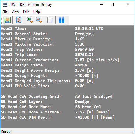
The final Generic Display could look something like this:
Return to: Trailing Suction Hopper Dredger - Online