
Qimera - Project Layers
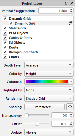
The Project Layers dock as show above allows the user to interact with the visual layers of the 3D scene.
Vertical Exaggeration
The vertical exaggeration field controls the exaggeration of the scene along the Z axis. Qimera uses a default exaggeration of 6× to make grid features more prominent, but an exaggeration of 1× can be used for accurate scaling.
Layers Tree
The layers tree shows all of the different layers in the current project. These layers are grouped by type.
Dynamic Grids
Dynamic grids are grids created from raw sonar or processed point source files and which automatically update when the underlying soundings are changed. Dynamic grids are the backbone of Qimera's point cleaning workflow. Most editing and filtering operation are conducted on a dynamic grid.
If there are pending edits to be applied to a dynamic grid, the auto-solve icon will appear to the right of the layer in the tree as shown below. Edits can be applied by pressing theAuto Process button or choosing 'Update From Edits' from the right click popup menu of a Dynamic Grid.
The active grid will be indicated by the pencil icon, to the right of the grid name.
Static Grids
Static Grids are grids which do not change when their underlying data changes. Static grids may be created inside Qimera by gridding points, imported from outside Qimera or created as static snapshots of a dynamic grid.
PFM Objects
PFM Objects are a legacy grid format that contains both the grid cells and their underlying point data. These were used for point editing in previous versions of Fledermaus, but may be imported into Qimera for basic point cleaning.
Cables & Pipes
The Cables & Pipes group contains any cable or pipe objects created via the Cable/Pipe Detection Tool.
Sd Objects
The Sd Objects group is a catch-all for any other layer type not given its own dedicated category.
Route
The Route group contains the active project route, if any. A project can only contain one route. A route is a special line object imported from a .qgfline file that contains distance information for all points along the line. A route typically represents a planned survey line, a pipe or cable route or other line against which locations might be referenced.
When a route is present, any 2D position near that can be expressed in a route relative coordinate system known as KP and DX.
-
KP is the "along track" coordinate and represents the distance along the route. This is expressed in thousands of the horizontal survey unit, so for a survey conducted in metres, KP will be expressed in kilometres.
-
DX is the "across track" coordinate and represents the perpendicular distance between the given point and the nearest point on the route.
Background Charts
The Background Charts group is always empty, but its checkbox controls the visibility of the background charts in the scene when in 2D view.
Charts
Charts are electronic navigational charts in QPS's QNC format.
Attributes
Marker
This attribute is used by Point SD layers. It allows you to change the appearance of the point. The options are Circle, Square, Crosshair, Cube, Diamond, Cylinder, Sphere, Flag, Point, and None.
Point Size
This attribute is used by Point SD layers. It changes the size of the displayed marker.
Depth Layer
This attribute is used by Dynamic Grid layers. It changes the currently displayed depth layer. The options are Average, Shallow, Deep and CUBE.
Color By
This attribute is used by Dynamic Grid layers. It changes how the grid is colored. The options are Height, Uncertainty (95% c.i.), Sounding Density, Checked Flag, Plotted Flag, Feature Flag, Suspect Flag and Cell of Interest. If the Dynamic Grid was built with CUBE, the options would also include # of Hypothesis, Uncertainty, and Hypothesis Strength. Note that the CUBE Uncertainty layer is different than the normal uncertainty layer. The normal Uncertainty layer represents the normal standard deviation, scaled to 95% c.l., of all accepted soundings in the grid cell, regardless of what CUBE believes the depth to be and regardless of the potential number of CUBE hypotheses. On the other hand, the CUBE Uncertainty layer reflects the standard deviation, scaled to 95% c.l., for ONLY those soundings that are associated with the selected hypothesis. If the Dynamic Grid was built with Coverage and Datetime, the options would also include Coverage and Date Time
To color by the cell of interest first use the flag grid cells operation on the grid. See Flag Grid Cell Dialog.
Color By
This attribute is used by Point SD layers. It changes how the marker is colored. The options are Solid, X, Y, Z and any other imported custom attributes contained by the SD object.
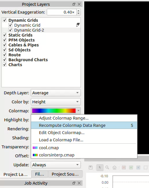
Colormap
This popup allows you to see the currently selected colormap. It also allows you to select a colormap file, edit the current colormap, adjust the colormap range, and recompute the colormap range for the selected dynamic grid (not the active Dynamic Grid) based on the accepted data range. Recomputing the colormap range will also change the user range to the accepted data range.
Highlight By
This attribute is used by Dynamic Grid layers. It changes how the grid is highlighted. The options are None, Checked Flag, Plotted Flag, Feature Flag and Cell of Interest. To highlight by the cell of interest first use the flag grid cells operation on the grid. See Flag Grid Cell Dialog.
Rendering
This attribute is used by Dynamic and Static Grids layers. This attribute changes the grid display to either a wire frame display, a solid shaded grid, or plates mode.
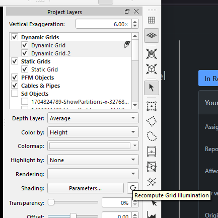
Shading
This attribute is used by Dynamic and Static Grid layers. This button launches the Shading Parameters dialog. The "Refresh" Icon will Recompute the Grid Illumination. This will launch a job to re-compute the grid illumination for the currently selected Dynamic Grid. This option is relevant only if you are in Mixed Shading mode. This is typically done automatically during dynamic grid generation. If you have an active selection, the computation will be done within the minimum bounding rectangle of that selection.
Transparency
This attribute is used by Image, Scalar, Dynamic, Static Grid layers and Plane SD Layers. It controls the transparency of the layer in the Scene.
Offset
This attribute is used by most 3D layers. It applies a small vertical offset to the layer. This is mostly useful for ensuring that one layer is drawn above or below another.
Height
This attribute is used by Image and Scalar layers. It controls the height location in the scene (Z).
Drape Image
This attribute is used by Static Grid layers. It drapes an Image or Scalar object onto the selected grid.
Drape Onto Scene
This attribute is used by Point and Line SD layers. It drapes each vertex onto the grid layers in the scene. The point nearest (below) the vertex is where it will drape.
Mask Out Grid Areas
This attribute is used by Image layers. It allows all visible Static or Dynamic Grids to mask out portions of the selected image.
Interpolate
This attribute is used by Image and Static Grid layers. It will reduce the visibility of pixel edges by smoothing the colormap based on surrounding pixels.
Update
This attribute is used by Dynamic Grid layers. It can be set to one of three update policies which control when the dynamic grid updates to changes in the underlying point data.
Color
This attribute is used by Plane SD layers. It changes the color of the plane.
Line Thickness
This attribute is used by Line SD layers. It changes the thickness of the line.
|
Update Policy |
Behavior |
|---|---|
|
Always |
The dynamic grid will automatically update whenever changes are made to the underlying point data. |
|
After Processing |
The dynamic grid will automatically update whenever a processing job modifies the underlying point data. Running any filters or manually cleaning in the 3D editor, swath editor or slice editor will not automatically cause an update, but will instead cause the grid to marked as needing an update. This allows one to do quick manual cleaning without having to wait for the grid to update after each edit. When edits are complete, the grid can be updated via its context menu, or by pressing theAuto Process button. |
|
Never |
The dynamic grid is completely disconnected from the changes to the underlying point data. The 3D editor cannot be launched on the grid. Neither processing jobs, filters, or the swath editor will cause the grid to update. Note that switching from Never to a different update policy will require a full grid update, which can be quite slow for large grids. |
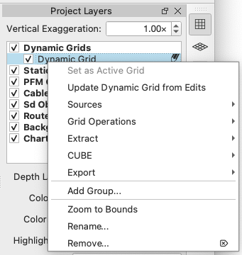
Context Menus
By right clicking on any item in the Project Layer's tree hierarchy a context menu will pop up.
Dynamic Grid Context Menu
Redisplay All Dynamic Grids
Show all of the dynamic grids in the project. Right click on the dynamic grid group for this option.
Set Active Grid
Make this selected grid the Active Grid.
Update Dynamic Grid From Edits
This action will update a selected dynamic grid with edits pending. Qimera will warn you with a list of grid names and area requiring update before proceeding. If any of your Dynamic Grid QPDs were used in another project, and edited, Qimera will detect this when it re-opens your project and will mark the grid as requiring update.
Sources
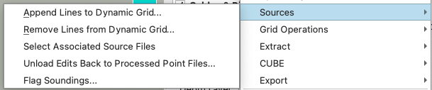
Append Lines to Dynamic Grid...
Launches the Append Lines to Dynamic Grid Dialog.
Remove Lines from Dynamic Grid...
Launches the Remove Lines Dialog.
Select Associated Source Files
This action will clear the current source item selection and select all the source files used to create the grid. Please note that Qimera does not support selecting multiple source file types simultaneously. If your grid was created from both raw and processed point files, a dialog will be displayed, allowing you to choose only one file type.
Unload Edits Back to Processed Point Files...
Launches the Unload Edits Back to Processed Point Files. The grid must contain a processed point file that supports unloading.
Flag Soundings...
Launches the Sounding Selection Dialog.
Grid Operations
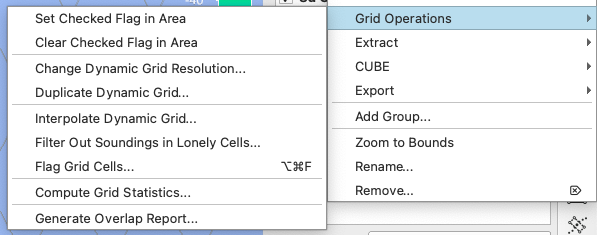
Set Checked Flag in Area...
This will set the checked bit flag in the cells covered by the current selection. This option will only work if you have a dynamic grid selected and a spatial area selected. You can then view checked areas by using the Highlight By option of the Qimera Project Layers Dock for Dynamic Grids. This bit can only be cleared by using the Reset Checked Area option below. The checked bit flag is also independent of the visited/edited areas seen in the Grid Edit Overview Dock.
Clear Checked Flag in Area...
This will clear the checked bit flag in the cells covered by the current selection. This option will only work if you have a dynamic grid selected and a spatial area selected.
Change Dynamic Grid Resolution...
Launches theChange Resolution dialog.
Duplicate Dynamic Grid...
Launches the Create Dynamic Grid Dialog with the same settings as the selected grid.
Interpolate Dynamic Grid...
Launches theInterpolate Dynamic Grid Dialog used to configure the interpolation algorithm. You can set the minimum neighbors, iterations and interpolation type.
Filter Out Soundings in Lonely Cells...
Launches theQimera Filter Out Soundings in Lonely Cells Dialog used to remove small blocks of cells detached from the main body of the dynamic grid.
Flag Grid Cells...
Launches the Flag Grid Cell Dialog.
Compute Grid Statistics...
Computes the grid statistics for a given plane height. See Grid Statistics Dialog.
Generate Overlap Report…
Launches the Generate Overlap Report Dialog.
Extract
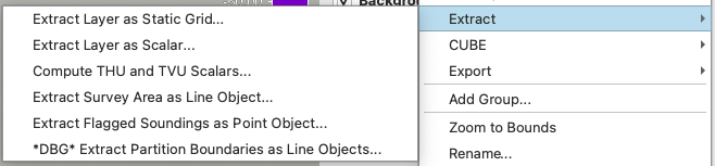
Extract Layer as Static Grid...
Launches the Snapshot as Static Grid Dialog.
Extract Layer as Scalar...
Launches the Extract Dynamic Grid Layer.
Compute THU and TVU Scalar...
Create total horizontal and vertical uncertainty Sd Objects.
Extract Survey Area as Line Object...
Saves the survey area as a SD line object.
Extract Flagged Soundings as Point Object...
Launches the Create Flag Markers.
CUBE
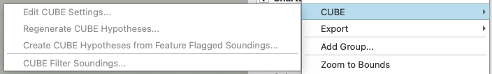
Edit CUBE Settings...
Launches the CUBE Settings Dialog.
Regenerate CUBE Hypotheses...
Launches the Re-Cube Area Dialog.
Create CUBE Hypotheses...
Launches the Create Custom Hypothesis from Features Dialog.
CUBE Filter Soundings...
Launches the CUBE Filter Soundings Dialog.
Export
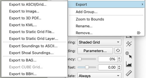
Export to ASCII/Grid...
Launches the Export ASCII/Grid Dialog.
Export to Image...
This option launches the Export Grid as Image Dialog, followed by a file browser dialog to select the filename of the exported image.
Export to 3D PDF...
This will open a file browser dialog to save the currently selected grid as a 3D PDF.
Export to KML...
This option launches the Export Grid to KML Dialog to export the currently selected grid to KML and KMZ formats.
Export to Static Grid File...
This will open a file browser to select the name for the exported Static Grid file.
Export to Static Grid Layer...
This will launch the Export Static Grid Layer dialog.
Export Soundings to ASCII...
Launches the Export Soundings to ASCII Dialog.
Export Shoal Soundings...
Launches the Export Shoal Soundings Dialog.
Export to BAG...
This will launch the Export BAG Grid Wizard.
Export CUBE Grid...
Export the CUBE grid to a .xyz file.
Export to BBH...
Export the dynamic grid to a .bbh file.
Static Grid Context Menu
Export
Export to ASCII/Grid...
Launches the Export Grid Dialog.
Export to Image...
This option launches the Export Grid as Image Dialog, followed by a file browser dialog to select the filename of the exported image.
Export to 3D PDF...
This will open a file browser dialog to save the currently selected grid as a 3D PDF.
Export to KML...
This option launches the Export Grid to KML Dialog to export the currently selected grid to KML and KMZ formats.
PFM Object Context Menu
Set Active Grid
Make this selected grid the Active Grid.
Unload PFM Edits
This action launches the PFM Unload Wizard which saves edits back to processed point files that support unloading.
Set Checked Flag in Area...
Flags the soundings as checked within a selected area.
Clear Checked Flag in Area...
Clears the checked flag within a selected area.
Cables & Pipes Context Menu
Edit Dynamic Cable / Pipe...
This feature will load the Dynamic Cable/Pipe in to theCable/Pipe TOP Detection Tool for inspection or modification.
Edit X-Point Listings...
Launches theGenerate/Edit X-Point Listings dialog to configure the number and property of X-point lines running parallel to the cable or pipe.
Clear X-Point Listings...
This will erase all X-Point listings configured via theGenerate/Edit X-Point Listings dialog.
Filter Soundings Directly Below Cable / Pipe...
This is a filter for cleaning data underneath the pipeline taking its diameter into account, which can be run along a KP-line. It automatically deletes data underneath the pipeline. It works kind of like stencil linked to the pipe diameter, and rejects everything below the pipe center and leaves the upper half circle untouched. If you wish to undo your changes, simply rerun the same filter but with the accept radio button selected. SeeFilter Below Dynamic Cable/Pipe dialog.
Run Cable / Pipe Analysis & Export...
Opens Cable/Pipe Analysis Dock.
Export to QGF Line...
Export the pipe to a .qgfline file.
Merge Dynamic Cable / Pipe...
If you select more than one Cable/Pipe, this option will let you merge dynamic cable/pipes via theMerge Dynamic Cable/Pipes dialog.
Sd Object Context Menu
Load Points into GeoPick tool...
This option is only available for SD point files. It will add the points into the Geo Pick Dock.
Use Line Object as Selection...
Shown only for line objects, this action replaces the current selection, if any, with a freehand selection having the same shape as the line. If the line is not closed, an additional, closing line segment is added.
Use Line Object as Profile...
Shown only for line objects, this action will create a profile object.
Use Line Object as Route...
Shown only for line objects, this action will create a route object.
Add Selection to Line Object...
Shown only for line objects, this action will add the current closed selection to the selected line object.
Create Cable/Pipe from Line Object...
Shown only for line objects, this action will create a Dynamic Pipe object.
Attach Scroll Selection to Line...
Forms a rectangular selection at the start of the route. You can use the W and S keys to step the selection forwards and backwards.
Export
Export options specific to the SD file type.
Route Context Menu
Load Route from QGF file...
This action allows setting the project's active route. If the project already has an active route, it will be replaced.
Create KP Marker Labels...
This actions creates a point object labeling KP values along the project's active route at a specified interval. The action is only enabled If the project has an active route.
Center View on KP...
This action will prompt you to enter a KP value along the project's active route and then move the view to be centered on that KP position.
Center Selection on KP...
This action will prompt you to enter a KP value along the project's active route and then move the selection (and the view) to be centered on that KP position. If you do not currently have a selection, the action will be disabled.
Attach Scroll Selection to Route...
This feature is used in combination with the Scroll Line Select Mode to have the selection follow that route.
Charts Context Menu
Create New Chart...
Import a .qnc file to create a new chart.
Lock / Unlock Editing...
This allows the user to control which layers are allowed to be edited. If you have a chart layer in your Layers Dock that is not in your project as a QNC file, it will be locked by default and you will not be able to unlock it for editing. If you have an external ENC(.000) that you want to edit, import it into your project using the Import Files option above.
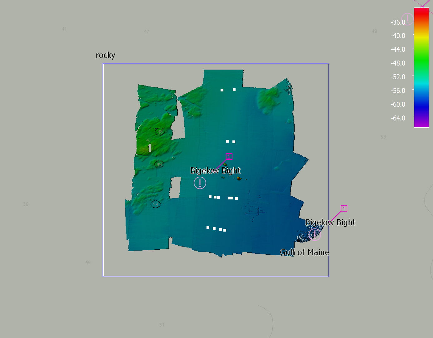
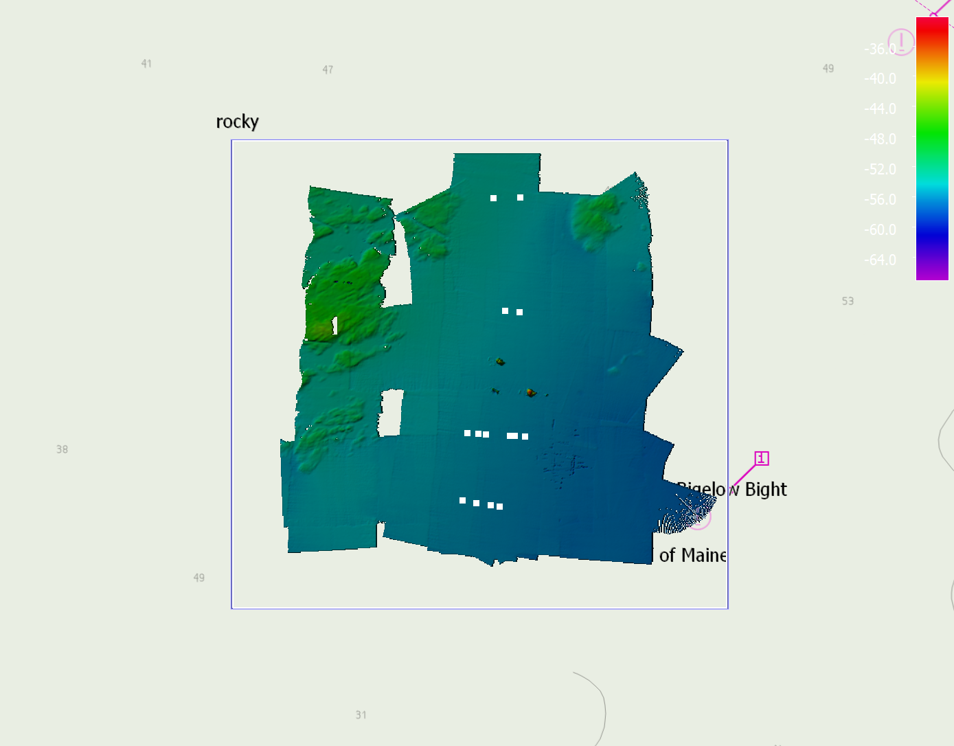
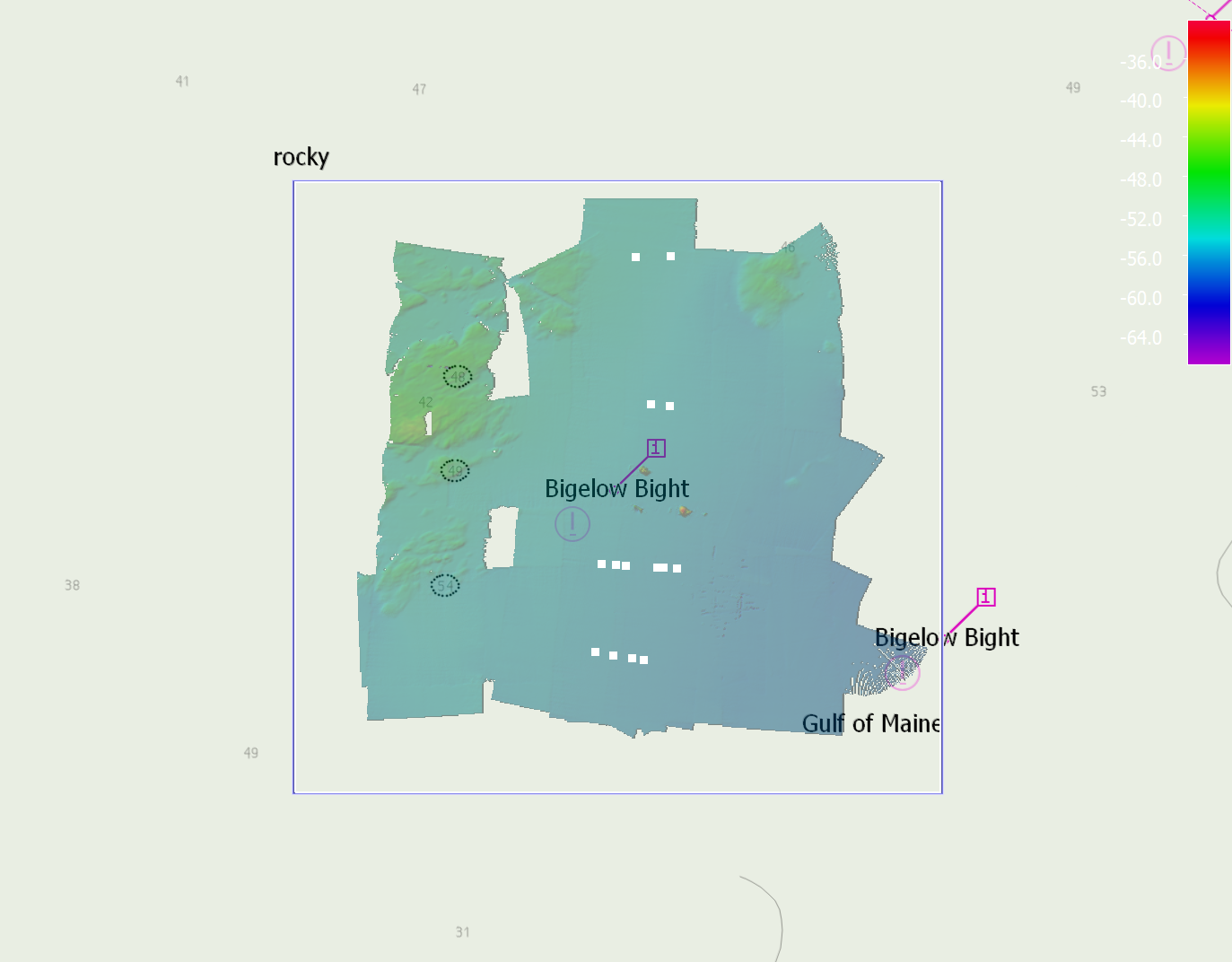
Chart on Top...
This will render the ENC charts on top of any dynamic grids without any filled in areas (left image below). By default, charts are drawn below any Dynamic Grids (middle image below) and you have to change the opacity of the Dynamic Grid in order to see ENC symbology underneath the grid (right image below). Remember that charts are only draw when Qimera is in 2D View.
Import Files...
This will import an ENC chart(.000) file, convert it to a QNC and save it in the project QNC folder.
Common Options
Add Files...
This action will add an SD object to the scene. If the SD object is in a different coordinate system than Qimera, it will be re-projected to the project coordinate system. If the context is for a Chart, it will add a QNC(.qnc) file to the layer. QNC files are the optimized versions of ENC(.000) files.
Add Group...
This action will add a custom named group to the tree hierarchy.
Organize...
Order the items in a group by name or by file path. You can also remove a group in this menu.
Zoom to Bounds...
This action will zoom the scene such that the current object fits the viewable area of the window.
Remove...
This action will remove the current selection from the project. Using the shortcut key 'Del' will also remove the current selection from the project.
Rename...
This action will rename the current file selected within the project and from its source location.
Return to:Qimera Interface
Return to:Dockable Windows