Description
The Nortek Binary driver supports the following system types:
-
Doppler Velocity Log (DVL) (Speed Log)
-
Magnitude (Velocity)
-
Direction (Angle)
-
-
Acoustic Doppler Current Profiler (ADCP)
-
Acceleration and Velocity
-
Metadata (Miscellaneous System)
-
Underwater Sensor
-
Sound Speed
-
Pressure / Depth
-
Altimeter
-
-
Heading (Gyro Compass)
-
Motion (Roll, Pitch)
Driver Information
Decoding Notes
The driver decodes the Nortek Binary format. This format is sometimes referred to as the AD2CP format. Currently the following record identifiers are supported:
|
Known usages |
Identifier |
Name |
Content |
|---|---|---|---|
|
DVL500 |
0x16 |
Data Format 3 |
ADCP, averaged data, 4 beams |
|
0x1B |
Data Format 21 |
DVL bottom track, 4 beams |
|
|
0x1D |
Data Format 22 |
DVL water track, 4 beams |
|
|
Nucleus1000
|
0xAA |
Altimeter |
Altimeter, 3 beams |
|
0xB4 |
|
DVL bottom track, 3 beams |
|
|
0xBE |
|
DVL water track, 3 beams |
|
|
0xD2 |
AHRS |
Motion & Heading |
The driver decodes the records as various system types.
The following system types may be supported depending on the record type:
-
Speed Log (DVL)
-
Velocity
-
Angle
-
-
Acoustic Doppler Current Profiler (adcp)
-
Acceleration Velocity Sensor
-
Miscellaneous System
-
Underwater Sensor
-
Sound Speed
-
Pressure / Depth
-
Altimeter
-
-
Gyro Compass
-
Motion System
Below you will find a table per record identifier which specifies the decoded information.
In order to connect a specific Qinsy observation/system to (a) particular record field(s) a slot identifier is used.
DVL Bottom Track (0x1B) (DF 21)
DVL Water Track (0x1D) (DF 22)
ADCP Averaged Data (0x16) (DF 3)
Nucleus Altimeter (0xAA)
Nucleus AHRS (0xB4)
Nucleus DVL Bottom Track (0xB4)
Nucleus DVL Water Track (0xBE)
Database Setup
It is important to use the same interfacing settings for all 'Nortek Binary' systems in your template setup.
Speed Log (DVL)
Click here to expand setup details...
-
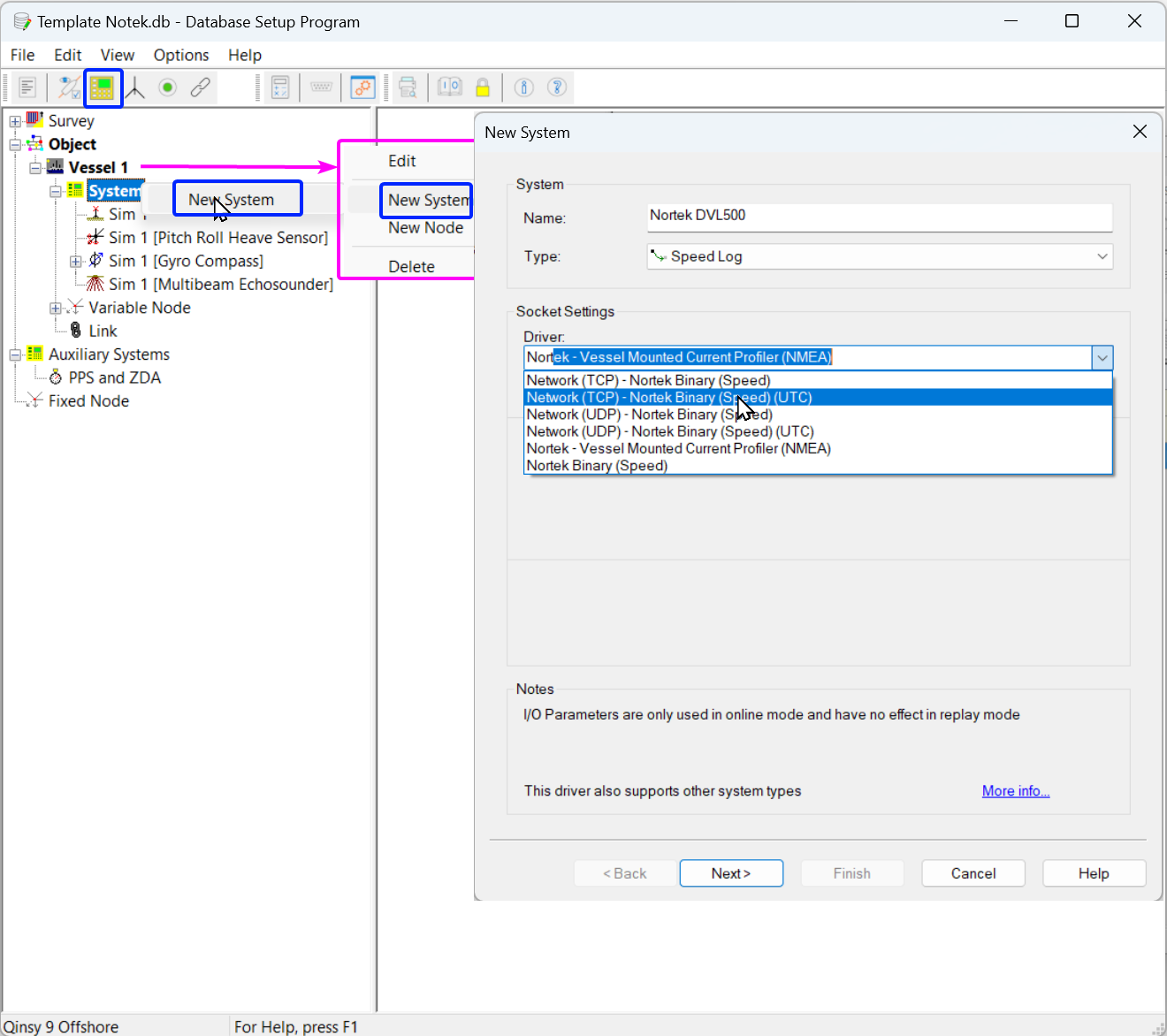
Add a new system
-
Enter a Name:
-
Nortek DVL500
-
Nortek Nucleus 1000
-
-
Select System Type: “Speed Log”
-
Start typing Nortek
-
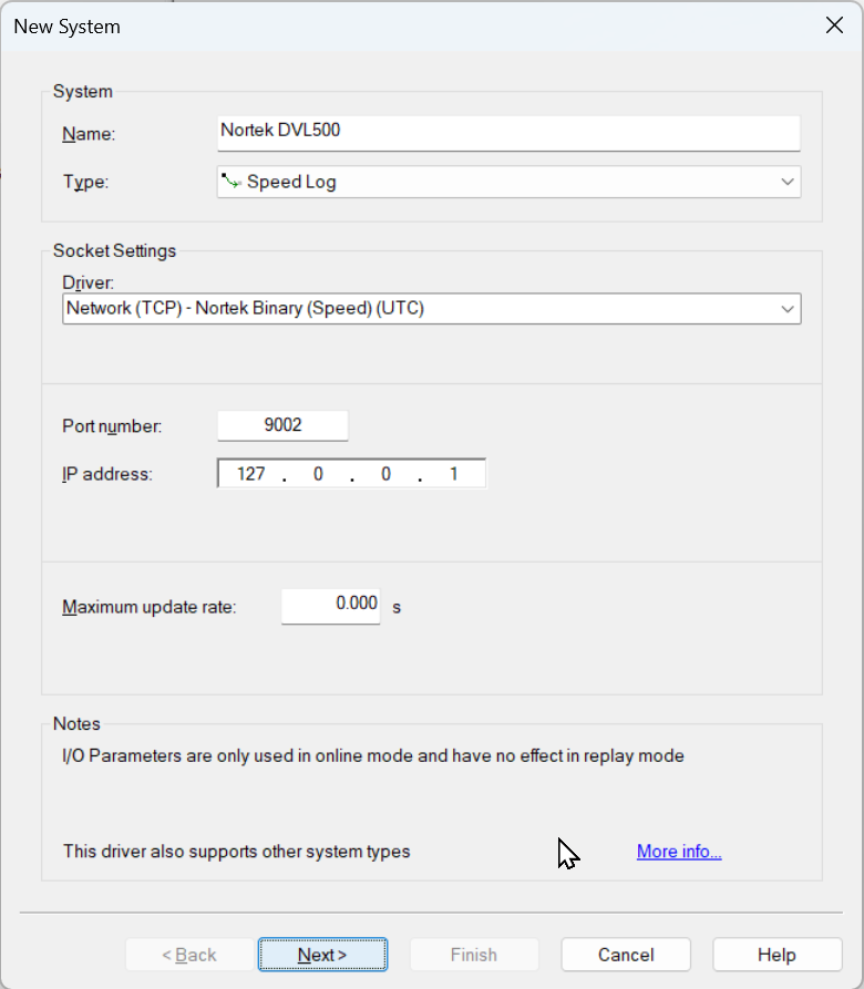
Select the required driver
-
(UTC) driver is preferred
Only then the driver is using time from the messages received (Auxiliary Systems needs to contain a Time Synchronization System)
-
-
-
Result
-
Press “Next >”
-
-
-
Define Observations
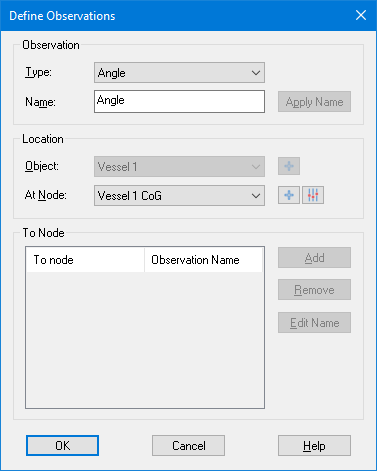
adding observations -
Add the required observation types you need.
-
Angle
-
Speed
-
-
-
Observation Definition
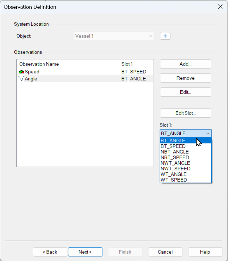
select slot values
-
Add the required Slot Identifiers (see decoding notes)
-
-
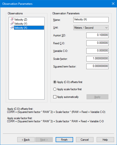
Observation Parameters
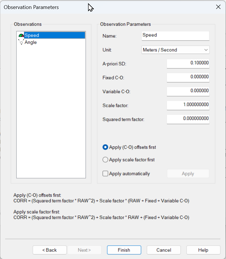
-
Here you can also change the default name of each observation and you may leave all parameters at their defaults.
-
You may change the default name for each observation as long as it doesn't exceed 16 characters.
-
This name is used Online in for example:
-
Observation Physics Display
-
Time Series Display
-
Alert Display
-
-
-
There is a DVL Calibration tool available Online to correct for the installation alignment, but refer to the manufacturer procedures if alternative methods are needed.
Online - Controller - Calibrations - DVL/ADCP Alignment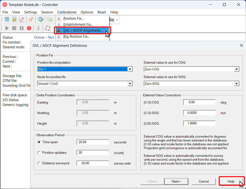
-
Check the Help for more information.
-
-
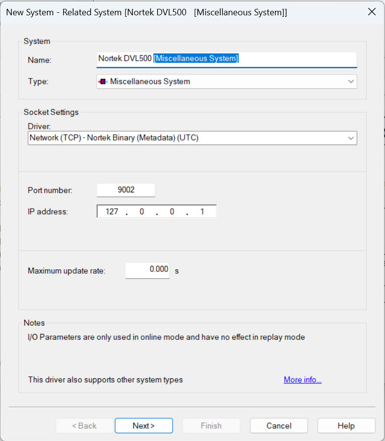
After you added your first system we will offer you to add more related system types that can be decoded by this driver:
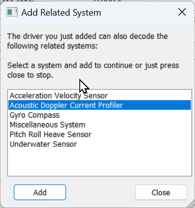
It offers all the systems supported by the driver (not all Nortek systems supply data for these Qinsy system types)
Please check the supported system types under the Decoding Notes above.
When you accidently aborted the wizard you can still add related systems by right clicking on the already added system type:
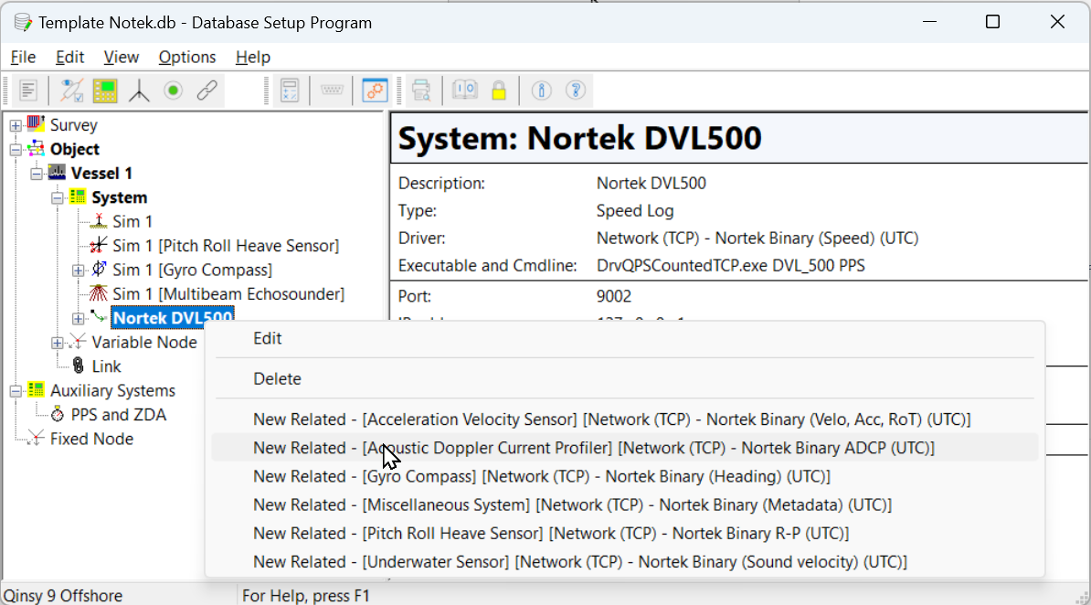
Acoustic Doppler Current Profiler
When interfacing a Nuclues1000 you can skip this system as its not supported.
Click here to expand setup details...
-
Select System Type: “Miscellaneous System”
-
New System - Related System [<NAME> [Miscellaneous System]]".
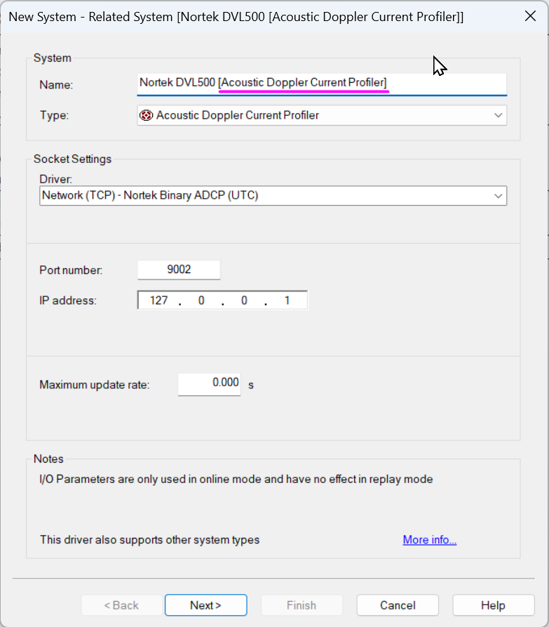
System Type is added to the name -
Driver Specific Parameters
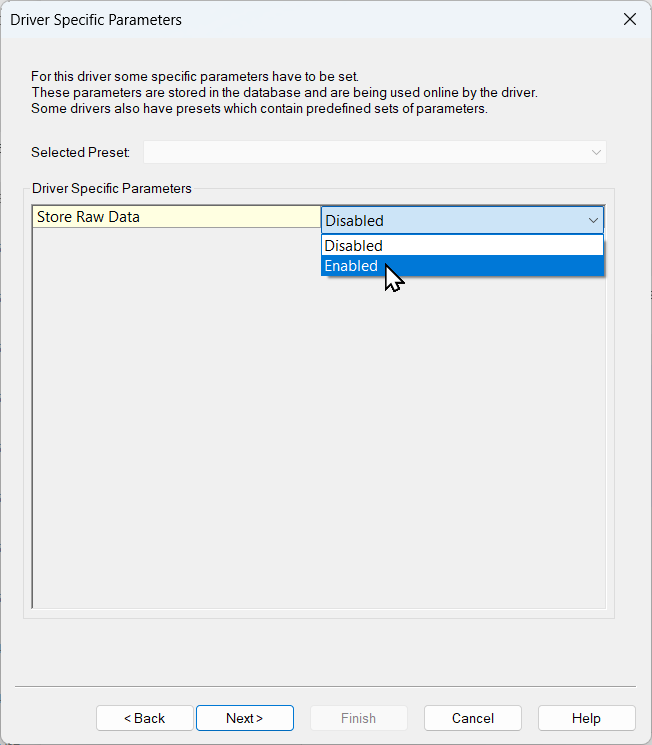
-
Raw data storage can be enabled for problem solving. Please enable when QPS Support asks for this.
-
-
ADCP Parameters
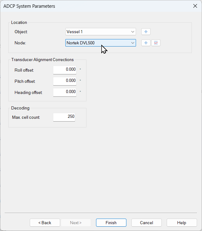
-
Set the 'Max. cell count' to the maximum number of ADCP depth cells that you expect to receive from the instrument.
-
-
Warning
There are no procedures to determine the alignment correction in Qinsy. Please refer to the manufacturer procedures to determine the heading offset.
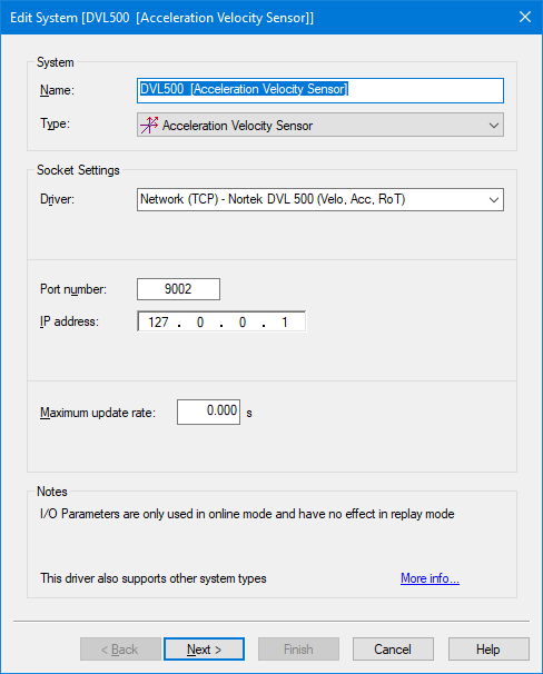
Acceleration Velocity Sensor
Click here to expand setup details...
Select System Type: “Acceleration Velocity Sensor”
-
New System - Related System [<NAME> [Acceleration Velocity Sensor]]".
-
Observation Definition
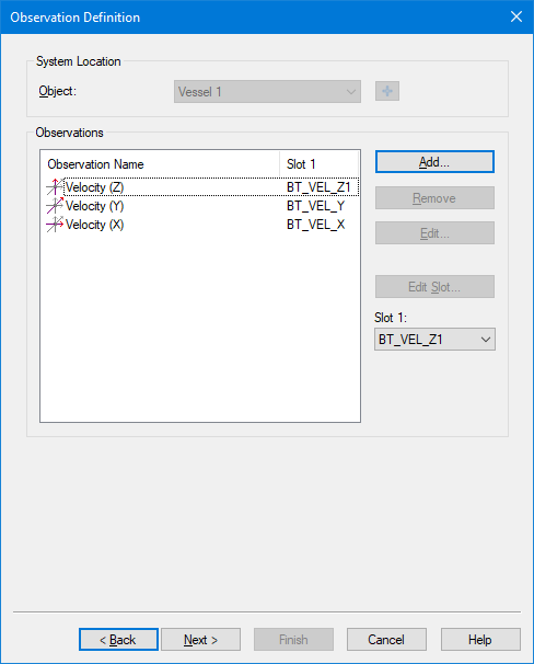
-
Add
-
Add the required observation types you need.
You may change the default name for each observation as long as it doesn't exceed 16 characters.
-
-
-
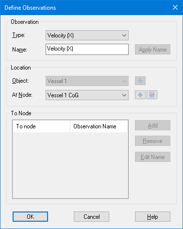
Observation Parameters
-
Here you can also change the default name of each observation and you may leave all parameters at their defaults.
You may change the default name for each observation as long as it doesn't exceed 16 characters.
-
Miscellaneous System
Click here to expand setup details...
These items are only recorded and displayed, but not used in computations. The can be used to fire Alarms.
-
Select System Type: “Miscellaneous System”
-
New System - Related System [<NAME> [Miscellaneous System]]".
-
Press “Next >”
-
-
Generic Observation Definition
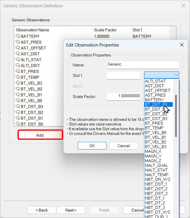
-
Here you can add any generic observations that you may want to monitor.
-
Each generic observation needs a unique Slot Id so the driver knows which field to decode.
-
It is highly recommended to use the drop-down selection for the correct Slot Id:
-
Note that the Slot Id is case-sensitive.
-
Possible Slot Id's may be found in the Slot Identifier column above.
-
-
-
-
Observation Parameters
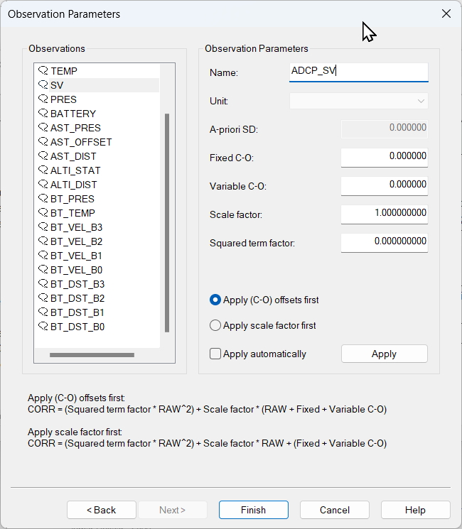
-
Here you can also change the default name of each observation as long as it doesn't exceed 16 characters.
-
-
Gyro
Click here to expand setup details...
-
Select System Type: “Gyro”
-
New System - Related System [<NAME> [Gyro System]]
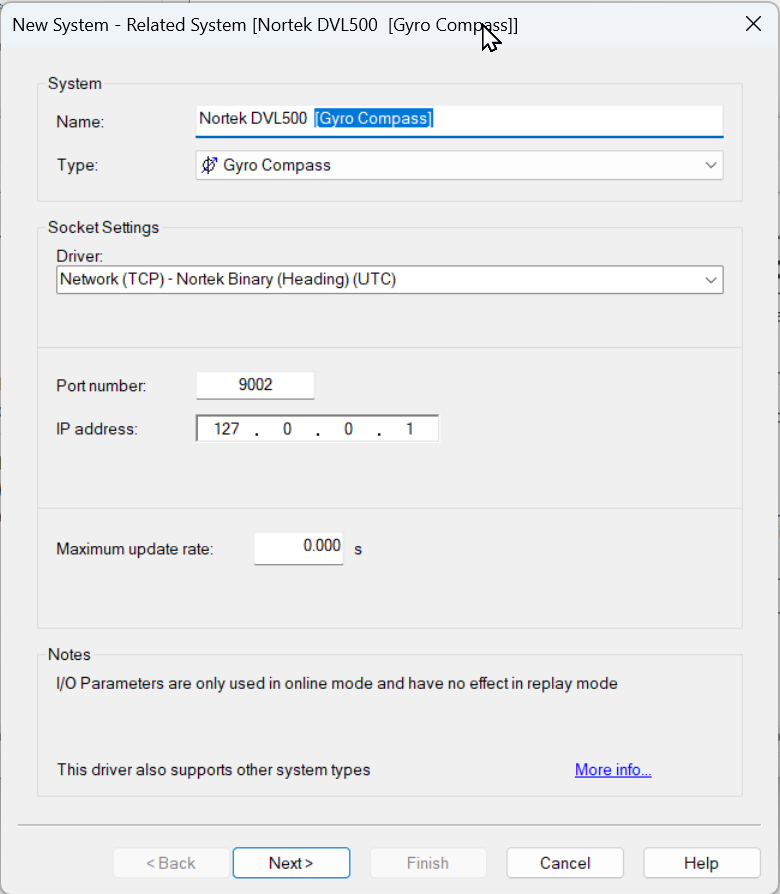
-
Press “Next >”
-
-
Gyro Observation Parameters
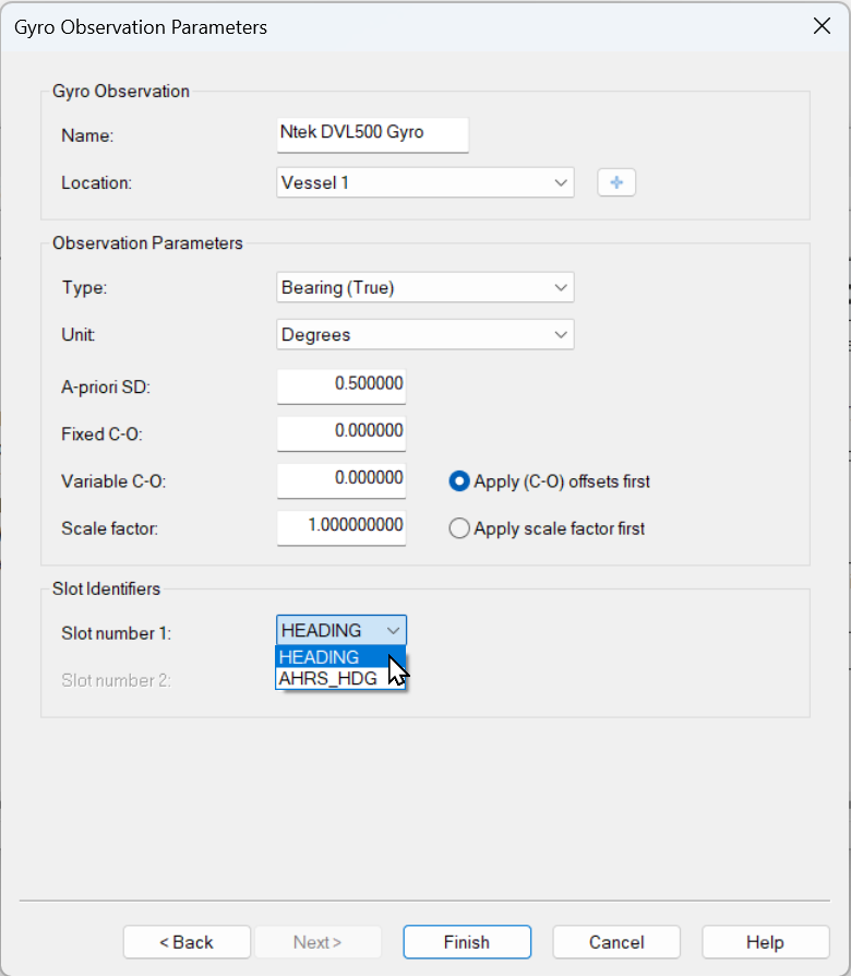
-
Update the Name (Max 16 characters)
-
Select the correct object for the location.
-
Slot numbers may be selected from the drop down list (see also Slot Identifier column above).
-
Press “Finish”
-
-
Pitch Roll Heave Sensor
Click here to expand setup details...
-
Select System Type: “Pitch Roll Heave Sensor”
-
New System - Related System [<NAME> [Pitch Roll Heave Sensor]]
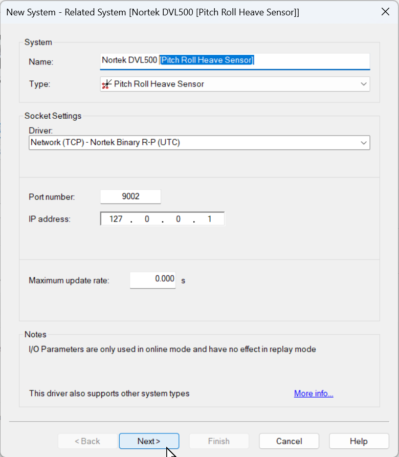
-
Press “Next >”
-
-
Motion Sensor Parameters
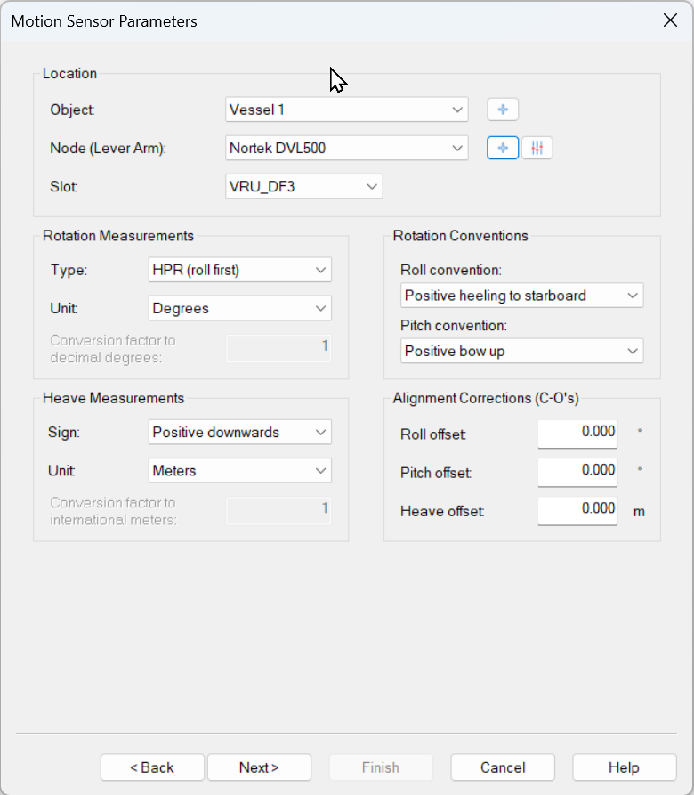
-
Select the correct Node location. Normally this will be the node location of the unit mounted on the object (main survey vessel/ROV/ect)
-
The correct Slot Identifier (see decoding notes) should be selected
-
-
Motion Sensor Parameter 2
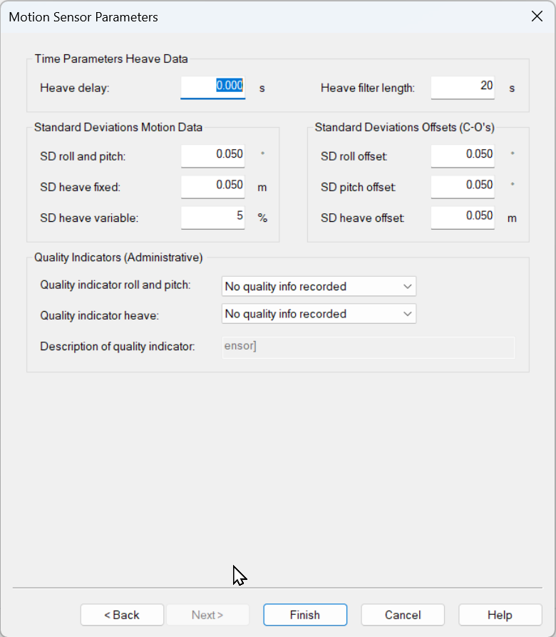
-
You may leave these settings at their defaults.
-
-
Online
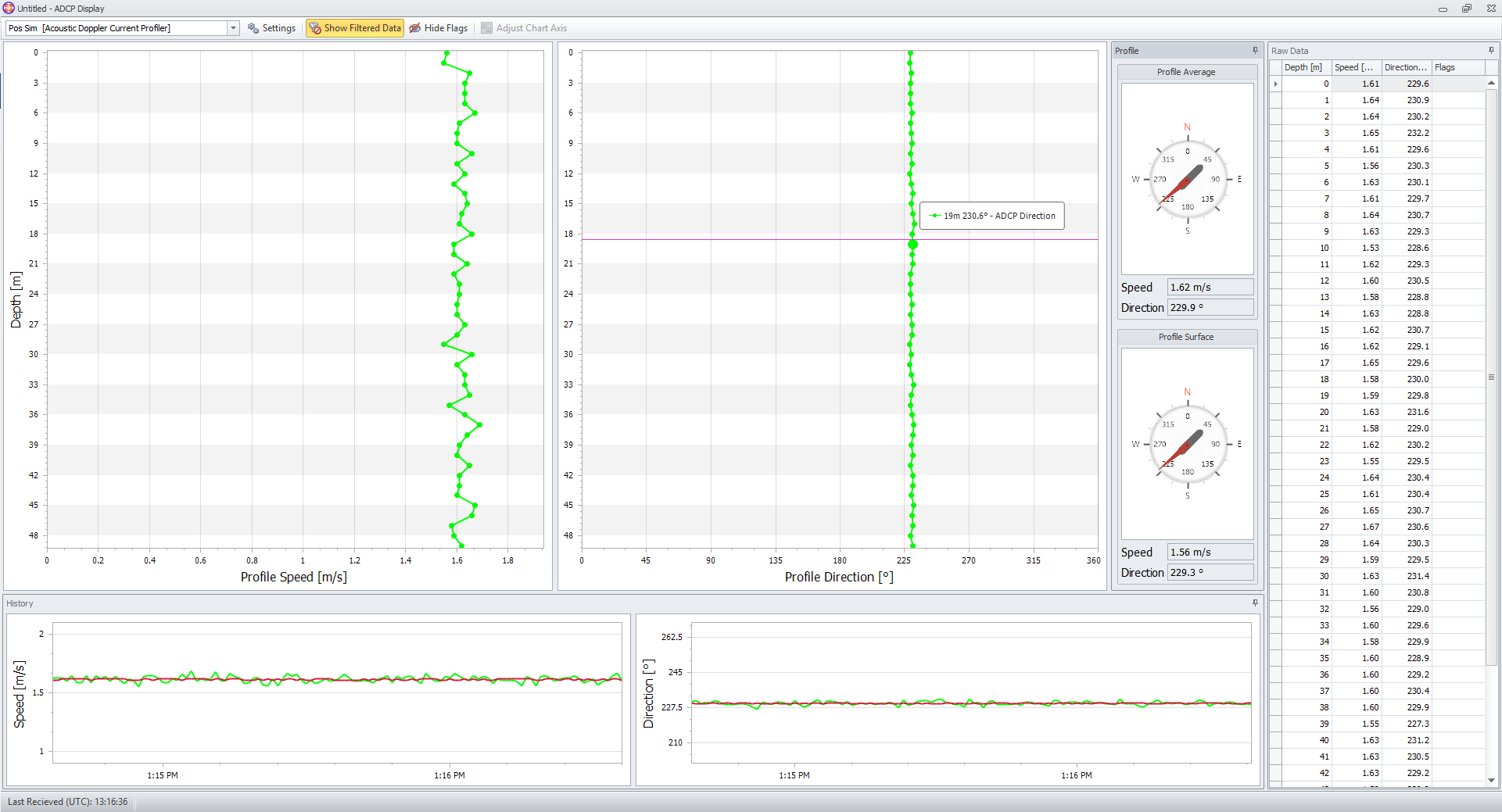
ADCP Display
https://qpssoftware.scrollhelp.site/qinsy/9.5/how-to-adcp
The ADCP Display shows the ADCP current direction and speed data in the following charts:
-
Profile charts through the water column;
-
History charts on average and surface;
-
Compass view on average and surface;
-
Raw data.
Info
The information bar of the display can contain warnings on decoded ADCP data
Additional Information
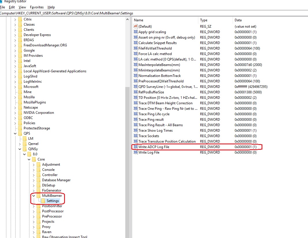
Registry settings
To log data to a text file in the log folder use the following registry key: