Network - Qinsy Remote Control Telemetry R-P (UTC)(UDP) - 03
Description
This driver is used to exchange position, heading and attitude information between a number of objects via a radio link. The objects may be survey vessels, tugs, ROVs, etc.
One of the objects is designated as the master object. The other objects are designated as slave objects.
On each object the Qinsy Survey software needs to be operational. The driver was developed and tested using SATEL's SATELLINE-2ASX Radios running at 9600 baud.
The drivers operate using a time slot principle. This means that each driver is allocated a time slot with a predefined duration.
The start of the time slot is marked by a query message which is transmitted by the driver on the master object.
This query message contains a slot id which determines which object is allowed to send data.
Once an object receives a query message with the destination slot id set to its own slot id it will respond with a response message which contains the position, heading and attitude information of the reference/COG node from the priority computation.
All objects receive this response message and may decide to decode the information based on the defined input drivers.
To allow the definition of the output driver and input drivers entries in the template database the following system types are available:
Position Navigation System
Gyro Compass
Pitch, Roll and Heave Sensor
Output System
Driver Information
Interfacing Notes
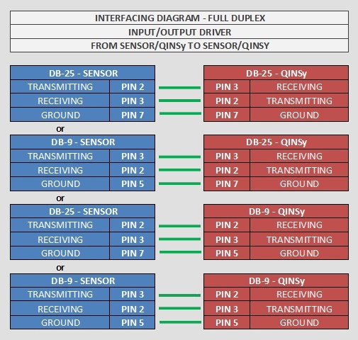
The following cable wiring (three-way) was sufficient for the Satelline 2ASX radios which were used during the development of the driver.
Different wiring may be required for different radios. Please consult the radio manuals for other radios.
Database Setup
This section contains additional notes for the setup of a network in the 'Database Setup' program.
For each remote object the following Systems need to be defined:
Position Navigation System (required)
Gyro Compass (optional)
Pitch, Roll and Heave Sensor (optional).
The slot identifiers entered in these systems should match the slot identifiers on the other Qinsy instances. It is advised to plan the slot identifiers assignments before building the template databases.
An example assignment may be found in the table below:
Vessel | Slot Identifier |
|---|---|
RSV | 1 |
Leading tug | 2 |
Trailing tug | 3 |
Work boat | 4 |
If you have defined at least one of the above drivers, then there is no need to define an output driver.
Only define an Output System in case you are not interested in receiving information from the other vessels, but you do need to send your local information to the others.
Online
Controller
There is no need to set up any parameters in the Controller program. The driver will automatically select the CoG node of each local object using the priority settings as defined in the Controller.
Online, Qinsy output drivers will usually 'skew' an output position to the output time, using the current speed and course computed for the last available position.
However, DrvRemoteController will NOT do that: the last position with corresponding time tag will be sent over and over again, until a new position (with new time) becomes available.
At the other (receiving) side, it depends on which driver version has been selected.
If the UTC/PPS version is used, then DrvRemoteController will use the time tag from the transferred position data string and will recognize that the position from the remote vessel has not been updated.
If the non-UTC/PPS version is used, then DrvRemoteController will issue a new local system time tag for each newly received position. What happens next, depends on the Computation Settings as defined on the "Position Results" tab for each vessel.
Driver
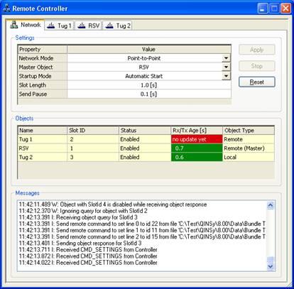
This paragraph describes the user interface (UI) of the driver. The UI of the driver consists of a dialog with multiple tab pages. The first tab page called 'Network' contains the radio link 'network' settings of the driver. The settings on the tab page are applicable to all objects. Besides the 'Network' tab page there is a tab page for each object which is defined in the used template database. The titles of each tab page are derived from the object names. In this document these tab pages are called 'Object' tab pages.
'Network' tab page
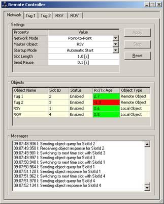
Below you will find a table with all UI elements and their descriptions:
UI Element | Description |
|---|---|
'Settings' Grid Control | This grid control contains all network wide settings that may be changed by the user. In normal circumstance these settings should be the same on all objects. A description of each setting is given in a table below. |
'Apply' Button | This button is used to confirm and activate any changes made in the 'Settings' grid control. |
'Start/Stop' Button | This button is used to manually enable/disable the radio network. Only active when 'Startup Mode' setting is set to 'Manual Startup'. |
'Reset' Button | This button is used to reset the network. This includes the scheduler on the 'Master' object and the serial port to which the radio is connected. |
'Objects' Grid Control | This grid control is used to monitor the state of the connections to each defined object. A description of each column is given in a table below. |
'Messages' List Box | This list box is used to monitor the exchange of message and any error conditions. It is primarily used for trouble shooting. A description of all possible messages may be found in a table below. |
Below you will find a table with all the settings and their descriptions which may be found in the 'Settings' grid control:
Settings | Description |
|---|---|
Network Mode | Mode in which the radio is operating. Currently only Point-to-Point mode is possible. May be expanded with other modes in future versions. |
Master Object | Object that is responsible for controlling the network. Within the whole network there should be only one master object. |
Startup Mode | Mode which describes how the driver behaves on startup. 'Manual Start' requires the user to use the Start/Stop button to toggle the state of the network. 'Automatic Start' causes the driver to start automatically. |
Anchor Information | When this setting is enabled on the master object, all locally defined anchors will be broadcast as so-called 'remote anchors'. When this setting is enabled on a slave object, possible transmitted anchors from the master will be received as 'remote anchors'. Remote anchors are purely for display: their information is visible in a Navigation Display but you can not actively do anchor handling with them: 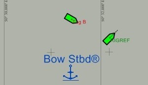  The advantage of using this option to send anchor information across the vessel spread is that it makes the use of a dedicated Anchor Output / Anchor Input driver obsolete. |
Slot Length | Length of the used time slot in seconds. Every defined object gets this amount of time to answer after an object query message is sent. |
Send Pause | Length of pause between the transmissions of two consecutive messages. This setting is used to make sure that the radios do not combine certain messages in a single message. |
Below you will find a table with all columns and their descriptions which may be found in the 'Objects' grid control:
Column | Description |
|---|---|
Object Name | The name of the object as entered in the 'Database Setup' program. |
Slot ID | Slot ID as entered in the 'Database Setup' program for remote objects and in this driver for the 'Local' objects. |
Status | Status of the object. Possible values are 'Enabled' and 'Disabled'. |
Rx/Tx Age | Number of seconds since the last message related to this object was received/transmitted. |
Object Type | The type of the object. 'Local' objects are computed on this PC and their results are sent via the radio network to other PCs. 'Remote' objects are computed on another PC and are sent via the network to this PC. |
Here you will find a table of all the possible status/error messages and their descriptions:
'Object' tab page
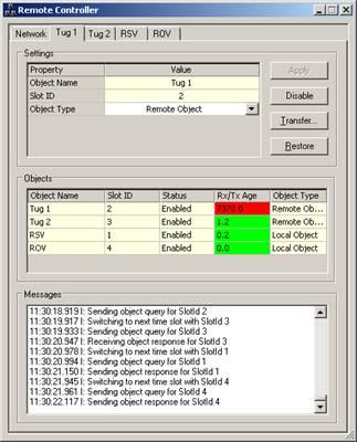
Below you will find a table with all UI elements and their descriptions:
UI Element | Description |
|---|---|
'Settings' Grid Control | This grid control contains all object specific settings that may be changed by the user. A description of each setting is given in a table below. |
'Apply' Button | This button is used to confirm and activate any changes made in the 'Settings' grid control. |
'Disable/Enable' Button | This button is used to manually enable/disable an object. |
'Transfer' Button | This button is used to transfer a file from the Master object to a slave object. Currently it is not possible to transfer files from slave to a master object or between two slave objects. A work-around for this limitation is to temporarily change the master object on all instances of the driver. |
'Restore' Button | This button us used to restore the backup of a display set on a remote object. This allows the user on the master object to restore a previously backed up display set on a slave object. |
'Objects' Grid Control | This grid control is used to monitor the state of the connections to each defined object. A description of each column may be found in the 'Network' tab page description. |
'Messages' List Box | This list box is used to monitor the exchange of message and any error conditions. It is primarily used for trouble shooting. A description of all possible messages may be found in the 'Network' tab page description. |
Below you will find a table with all the settings and their descriptions which may be found in the 'Settings' grid control:
Settings | Description |
|---|---|
Object Name | The name of the object as entered in the 'Database Setup' program. |
Slot ID | Slot ID as entered in the 'Database Setup' program for remote objects and in this driver for the 'Local' objects. This setting is read-only for remote objects. By design, slot IDs must be in the range from 1 to 255, but actually there is no check on the slot ID in the driver itself. |
Object Type | The type of the object. 'Local' objects are computed on this PC and their results are sent via the radio network to other PCs. 'Remote' objects are computed on another PC and sent via the network to this PC. These settings may be changed but this should not be necessary in normal circumstances. |
Drivers IO Notes
Below you will find a table with the possible command line options for the 'drivers.io' file:
Option | Description |
|---|---|
SATEL3AS | Driver mode which is used to support different types of radios. Currently not used. |
PPS | Driver will use the time tag from the message. Without this option the driver issues a new time tag at reception of the messages. |
Registry Settings
The registry settings loaded when the driver starts up, can be found in the following location:
[ HKEY_CURRENT_USER \ Software \ QPS \ Qinsy \ 9.0 \ Drivers \ DrvRemoteController \ Settings ]
Some of the registry settings for DrvRemoteController can be changed by clicking on the title bar:
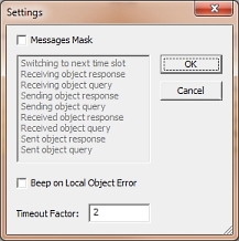
Other settings should be changed manually. For example, the LogLevel values to create a log file:
Value | Level | Description |
|---|---|---|
0 | Disabled | Output disabled |
1 | Low | Output Error and Fatal messages |
2 | Medium | Output Info and Warning messages too |
3 | High | Output Debug and Test messages too |
Additional Information
Below you will find some additional notes on the usage of the messages.
Remote Line Control
In order to allow the master driver to control the main line and additional lines on the slave objects the query message contains the path, record id and orientation of each line which needs to be sent to a slave object.
The used line database file needs to be available on the slave computer. This can be achieved by using the transfer option, see the File Transfer paragraph below for more information.
Each slave object receives the main line information and any additional lines for which the description field matches the slave object name.
The lines that are part of the object query message are used to control the main line and additional lines on the slave object. The main line on the master object is always sent to the slave object.
An additional line is sent to a slave object if the description field of the additional line matches the slave object name. Multiple additional lines may sent as shown below:
File Transfer
The driver on the master object is capable of sending a file to a slave object. In order to perform the transfer the whole file is read into memory. Subsequently the buffered data is sent to the slave object in one or more segments.
Each segment is checked on the slave side before an acknowledgment is sent to the master object. The transfer may be aborted by resetting the driver via the UI. While the transfer is in progress the regular exchange of position, heading and attitude information is suspended.
The maximum retry time for a single fragment may be controlled via the registry setting "File Transfer Timeout". The default value is 30 seconds which means that a segment needs to be successfully sent via the radio within 30 seconds otherwise the transfer is aborted by the driver.
Once the file transfer is complete and all segments have been received by the slave driver a CRC value is computed over the content of the file. In case this CRC does not match the CRC value which is part of the content a File CRC Error message is sent to the master driver.
This message triggers a message box to notify the user that the file transfer was aborted and that he/she should restart the file transfer.
In case the CRC values do match, the file is written to disk and a message box is triggered by the Master driver to inform the user that the transfer was successful.
Remote Display Restore
The driver on the master object has the ability to restore a display which was backed up previously on one of the slave objects.
The backup option can be found in the Display Manager under Manage Sets. The restore is accomplished by sending a command to the driver on the slave object which forwards this command to the Controller which is running on the slave object.
An acknowledgment is sent once the command has been received and forwarded. The maximum retry time for the command may be controlled via the registry setting "Remote Command Timeout".
The default value is 10 seconds which means that a command needs to be successfully sent via the radio within 10 seconds otherwise the transfer is aborted by the driver.
