
Description
This is a driver with user-interface in order to encode for - and decode messages from an ROV integrated with a:
-
PHINS / ROVINS
-
Doppler
-
USBL/LBL
-
Bathy (Depth Sensor) system
During normal operation the PHINS / ROVINS will establish an accurate position for the ROV based on the integration of Inertial, Doppler, USBL, Depth Sensor and Surface Positioning (Computation Node Result) information.
This driver will send the necessary surface positioning information to the PHINS / ROVINS.
At the same time it will read and decode the integrated accurate ROV position and attitude data, which can be used in a separate Computation Setup.
It is advised to interface the DVL (Doppler) and Bathy (Depth sensor) devices directly to the PHINS to prevent observation delays.
There are two versions of this driver: a network one and a serial one.
-
For the serial driver version, receiving data from, and sending data to, is done via the same serial COM port.
-
For the network driver version, receiving data from, and sending data to, is also done via the same LAN UDP port (by default).
However in the Options menu you can change the output port number PLUS ONE.
The user-interface for both drivers is exactly the same, only the I/O protocol is different.
See also the Interfacing Notes under the tab System Interfacing.
In case your setup does not require to receive any data from the PHINS, and you only need to send data to the PHINS, see the additional comments made in the Output setup section under the Qinsy Config tab.
|
ROVINS |
PHINS |
PHINS 6000 |
|---|---|---|
|
|
|
Driver Information
Coding Notes
Encoding Notes
Encoding
No information available
System Interfacing
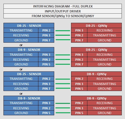
For the serial driver version, output will take place via the same serial COM port as the incoming messages, therefore one should take the following wiring diagram into account when using I/O cables and connectors:
INS setup
When setting up the Halliburton input in the INS please enter the following items:
-
Lever Arms: Offset location for which Qinsy is calculating a position.
-
Tip: it could be easy to let Qinsy calculate a position for the INS. This could prevent making mistakes with lever arms.
-
-
Beacon Code: Input Beacon ID: Not necessary, you can leave this empty!
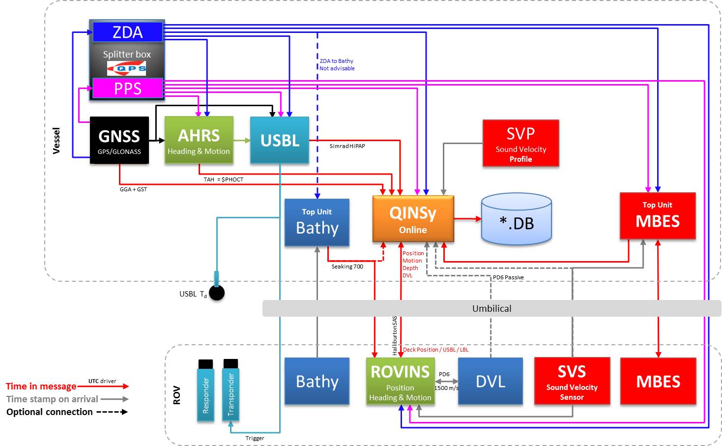
Interface overview
The following overview gives an example in which the Halliburton protocol can be used.
If you look at the red line between Qinsy and the ROVINS, you'll notice that it is a two way communication.
Procedural information can be found under the Qinsy Online tab.
Database Setup - Output
The idea of this driver is to let Qinsy calculate an initial position for the INS and then get an improved result in return.
There are 2 ways of doing this. You can use both options. Use whichever is easiest for your Qinsy setup.
-
Using 2 Computations:
-
Computation 1 for the output Qinsy → INS
-
Use Qinsy to calculate the INS location using either an offset onboard or a USBL/LBL.
-
-
Computation 2 for the input INS → Qinsy
-
Decode the position result + Depth coming from the INS.
-
-
-
Using 2 Objects:
-
-
Object 1 for the output Qinsy → INS
-
Use Qinsy to calculate the INS location using either an offset onboard or a USBL/LBL.
-
-
Object 2 for the input INS → Qinsy
-
Decode the position result + Depth coming from the INS.
-
-
Database Setup - Decoding Halliburton
This part will describe which system types can be added to the Qinsy template setup to decode the info coming from the ROVINS (or another INS system capable of outputting these messages).
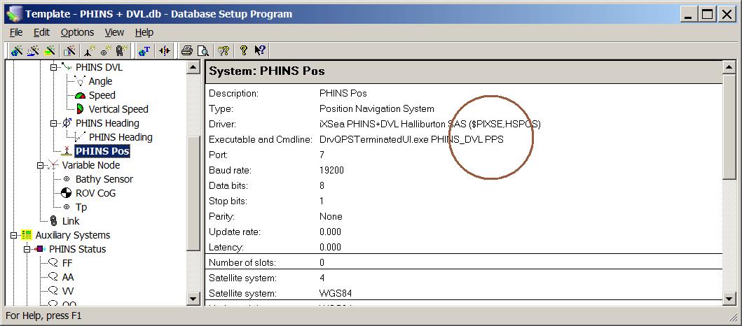
Position
-
In order to decode the position from the PHINS, add a Position Navigation System to the template and select driver "iXSea PHINS+DVL Halliburton SAS ($PIXSE,HSPOS)".
On the second wizard page, select for Horizontal Datum 'WGS84', but for Vertical Datum select the Mean Sea Level Model (because the height will be derived from the decoded depth, with a negative sign).
It is highly recommended to set the Height Status to 'Unreliable' in the on-line Computation Setup, in combination with the use of an ROV Depth observation (see below).
Heading
-
In order to decode the heading from the PHINS, add a Gyro Compass System to the template and select driver "iXSea PHINS+DVL Halliburton SAS ($PIXSE,HSATIT)".
Use the same I/O parameters (COM port, baud rate, etc.).
Motion / Attitude
-
In order to decode the pitch, roll and heave from the PHINS, add a Pitch, Roll and Heave Sensor System to the template and select driver "iXSea PHINS+DVL Halliburton SAS ($PIXSE,HSATIT)".
Use the same I/O parameters.
|
Roll convention: |
Positive heeling to starboard |
|
Pitch convention: |
Positive bow down
|
|
Heave Sign: |
|
Underwater
-
In order to decode an ROV Depth observation from the PHINS, add an Underwater System to the template and select driver "iXSea PHINS+DVL Halliburton SAS (ROV Depth)".
Use the same I/O parameters.
On the second wizard page, add an ROV Depth observation. Select for At Node the correct node on the ROV object.
The decoded depth will be taken from the Depth field of the '$PIXSE,HSPOS_' message.
You may also add an ROV Altitude observation: Add an ROV Altitude observation, select for the At Node the bathy sensor location on the ROV object.
Notice that this type of observation is not used by the Computation Setup, but it will be decoded, displayed and stored. The units on the last wizard page must be Meters.
In case your setup requires millimeter resolution (e.g. high res multibeam or subsea laser scanning surveys), please use driver "Generic - PHINS HYDROGRAPHY (ROV Depth)" in order to decode the depth using three decimals.
Speed Log
-
In order to decode a Doppler angle and speed from the PHINS:
-
Add a Speed Log System to the template and select driver "iXSea PHINS+DVL Halliburton SAS (PD6 Standard)".
Use the same I/O parameters. -
On the second wizard page and add the following observations:
-
Angle
-
Speed
-
Vertical Speed
The selected At Node must be of course located on the ROV object.
Notice that (at the time of this writing) the angle and speed observation are derived from the Longitudinal and Transverse velocity fields of the $PIXSE,HSATIT message, and not from the DVL messages.
The vertical speed observation is derived from the Vertical velocity field, also from the $PIXSE, HSATIT message.
The units on the last wizard page must be Meters/Second for the velocities, and Degrees for the angle observation. -
-
-
When you are using the USBL / LBL and would like to use the Speed Log to improve the USBL positioning results by using a Kalman Filter in Qinsy then please refer to:
-
Drivers Manual:
-
RDI Doppler BottomTrack Speed (ASCII) (Active) - 30 and have a look at the Kalman filter settings used
-
-
Knowledge Base:
-
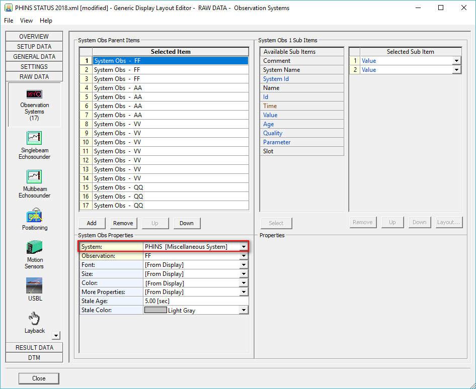
Status Information
-
Generic Display
In order to decode the status information from the PHINS, add a Miscellaneous System to the template and select driver "iXSea PHINS+DVL Halliburton SAS ($PIXSE,HSSTAT)".
Use the same I/O parameters.
On the second wizard page, add four Generic observations. The names and in particular the Slot Ids must be 'FF', 'AA', 'VV' and 'QQ' (in capitals!).
It is recommended to use an on-line a Generic Display in order to visualize the individual status information.
In the Generic Layout Editor you may use the 'MASK' operator on each value, in order to extract the individual 'bit' information.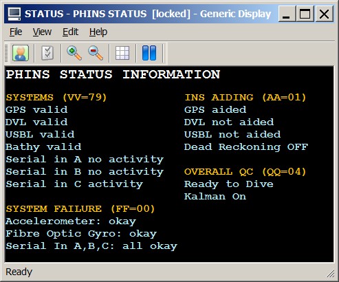
Download Generic Display Layout XML from this link as an example for displaying all the status information as shown above.
(This link will only work when connected to the internet.)
Doppler Information
-
In order to decode additional Doppler information from the PHINS, add a Miscellaneous System to the template and select driver "iXSea PHINS+DVL Halliburton SAS ($PIXSE,HSSTAT)".
Use the same I/O parameters.
On the second wizard page, add three Generic observations (All Slot Id's must be in capitals):
Name the first one e.g. 'DVL Velocity', with Slot Id 'SV', in order to decode the Sound Velocity (in m/s) from the DVL :TS message
Name the second one e.g. 'DVL Temperature', with Slot Id 'TEMP', in order to decode the temperature (in °C) from the DVL :TS message
Name the third one e.g. 'DVL Salinity', with Slot Id 'SAL', in order to decode the salinity (in parts per thousand) from the DVL :TS message.
Output
-
You do not need to define an extra output driver in the template setup. The driver will automatically output the messages to the same COM port as the incoming data (or to the same UDP port for the network driver version).
The output update rate and what messages to send can be selected while on-line. The information in the $PUSBA and $GPGGA message depends on the settings as selected by the user in the Setup menu. See for more information below in the Online Setup.
In case your setup does not require decoding of any incoming message from the PHINS, and you only have to output data to the PHINS, then you can select driver "iXSea PHINS+DVL Halliburton SAS (Output Only)" or "Network (UDP) - iXSea PHINS+DVL Halliburton SAS (Output Only)" .
This driver can not be selected in combination with other driver types (all types mentioned above) for the same COM or UDP port. The user-interface of this driver while you are online will be exactly the same.
CMD line
-
The driver will use the time-field in the PHINS messages for UTC time stamping, but only when Qinsy is (also) interfaced to a fully working Time Synchronization (PPS) system (time-tag and pulse). Otherwise time stamping will be done when data is received at the serial COMport.
-
When this 'Time Synchronization' parameter is omitted, time stamping is always done when data is received at the COM port.
-
To ensure if this parameter is used or not, you may check the information in the right-side pane of the System Properties in Database Setup.
Further, during start-up of this driver, a message will be displayed in the driver's message list whether the time-fields are used or not.
Qinsy Online
Work procedure
When working with this driver online, the following procedure is usually used. These setting can be entered in the user-interface (Options tab).
-
ZDA + GGA: When the ROV is on deck, you can use Qinsy to send a GGA position message.
-
The ROV usually has a fixed bracket on board, so you could measure in an offset during the Dimensional control survey for a point on the ROVINS.
-
-
ZDA: Then at some point, the ROV will be lowered in the water. When you start moving the ROV, you need to make sure you no longer send the GGA position message.
-
Just send the ZDA message for timing.
-
-
ZDA + PUSBA: As soon as the USBL is able to pick up a beacon on the ROV you can switch to the PUSBA message. This means you are now sending the Qinsy calculated result to the ROVINS.
The ROVINS will use this as an input and will send an improved position back to Qinsy (Position + Depth).*
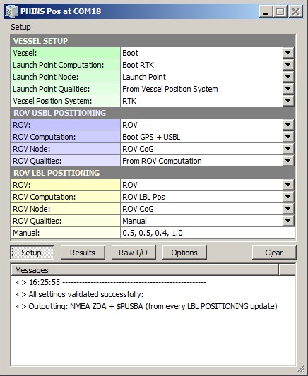
When going on-line for the first time, locate the driver, and change the Setup parameters:
Driver Layout Menu: Setup
More info on what you can select here can be found in the Qinsy Config tab.
|
|
VESSEL SETUP |
|---|---|
|
Vessel: |
Select from the available defined objects the vessel from which the ROV will be launched. |
|
Launch Point Computation: |
Select the computation and node for the launch point of the ROV on the vessel. This node will be formatted and outputted as the NMEA GGA message. |
|
Launch Point Node: |
Select the computation and node for the launch point of the ROV on the vessel. This node will be formatted and outputted as the NMEA GGA message. |
|
Launch Point Qualities: |
Select whether to use the GPS quality flag, Number of satellites and the HDOP value straight from the raw data of the selected Vessel Position System, or enter the values manually. These values are used to format the output NMEA GGA message. |
|
Manual: |
Manual quality values for the output NMEA GGA message. Enter the three values comma-separated ('q, ss, h.h'): GPS Quality, Number of Satellites, HDOP. |
|
Vessel Position System: |
Select the system that is used to position the vessel. This system is used to retrieve the GPS Quality and Number of satellites. |
|
|
ROV USBL POSITIONING |
|
ROV: |
Select from the available defined objects the ROV object that is positioned by a USBL system. |
|
ROV Computation: |
Select the USBL computation and node for the ROV. This node will be formatted and outputted as the $PUSBA message.
|
|
ROV Node: |
Select the USBL computation and node for the ROV. This node will be formatted and outputted as the $PUSBA message. |
|
ROV Qualities: |
Select whether to use positioning error estimates as computed by Qinsy using the selected ROV Computation, or enter the values manually. These value are used to format the output $PUSBA message. |
|
Manual: |
Manual positioning error estimates entries and age of data value for the output $PUSBA message. Enter the four values comma-separated ('±ccc.c, ±ccc.c,±ccc.c, aa.a'): Variance Latitude (in meters), Variance Longitude (in meters), Variance Depth (in meters), Age of Data (in sec). |
|
|
ROV LBL POSITIONING |
|
ROV: |
Select from the available defined objects the ROV object that is positioned by an LBL system. |
|
ROV Computation: |
Select the LBL computation and node for the ROV. This node will be formatted and outputted as the $PUSBA message.
|
|
ROV Node: |
Select the LBL computation and node for the ROV. This node will be formatted and outputted as the $PUSBA message. |
|
ROV Qualities: |
Select whether to use:
These value are used to format the output $PUSBA message. |
|
Manual: |
Manual positioning error estimates entries and age of data value for the output $PUSBA message. Enter the four values comma-separated ('±ccc.c, ±ccc.c, ±ccc.c, aa.a'): Variance Latitude (in meters), Variance Longitude (in meters), Variance Depth (in meters), Age of Data (in seconds). |
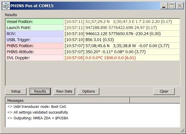
Driver Layout Menu: Results
|
Vessel Position: |
The last decoded statistics from the selected Vessel Position System. Displayed will be the "Update Time", Latitude and Longitude, GPS Quality Indicator, Number of Satellites, HDOP, Age of Differential Corrections and the age of the data (between brackets) in seconds. If this age exceeds 5 seconds, then the last decoded values are displayed in red color.
|
|
Launch Point: |
The last encoded position for the selected Launch Point Node which will be outputted as NMEA GGA. Displayed are the [Update Time], Easting and Northing, the Height and the age of the data (between brackets) in seconds. If this age exceeds 5 seconds, then the last encoded values are displayed in the color red. |
|
ROV: |
The last encoded position for the selected ROV which will be outputted as $PUSBA. Displayed are the [Update Time], the Easting and Northing, the Height and the age of the data (between brackets) in seconds. If this age exceeds 5 seconds, then the last encoded values are displayed in the color red. |
|
USBL Trigger: |
Information about the last updated USBL Transponder. This row is only visible when the $PUSBA message is outputted on USBL Trigger (see Options Menu). Displayed are the [Update Time], the Transponder Slot, the Seconds between the last two updates and the age of data (between brackets). If this age exceeds 5 seconds, then the last encoded values are displayed in red. |
|
PHINS Position: |
The last decoded position data from the PHINS messages. Displayed are the [Update Time], the Latitude and Longitude, Depth, Altitude and the age of the data (between brackets) in seconds. If this age exceeds 5 seconds, then the last decoded values are displayed in red. |
|
PHINS Attitude: |
The last decoded attitude data from the PHINS messages. Displayed are the [Update Time], the Heading, Pitch, Roll and Heave and the age of the data (between brackets) in seconds. If this age exceeds 5 seconds, then the last decoded values are displayed in red. |
|
DVL Doppler: |
The last decoded Doppler data from the DVL messages. Displayed are the [Update Time], Salinity in parts per thousand, Temperature in °C, Sound Velocity in m/s, Altitude in meters and the age of the data (between brackets) in seconds. If this age exceeds 5 seconds, then the last decoded values are displayed in red. |
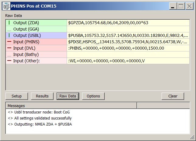
Driver Layout Menu: Raw Data
|
Output (ZDA) |
Last output NMEA ZDA message to the serial COM, or network UDP port. The indicator cycles when a complete message has been sent. If the last output took place more than 5 seconds ago, it will be displayed in gray. |
|
Output (GGA) |
Last output NMEA GGA message to the serial COM, or network UDP port. The indicator cycles when a complete message has been sent. If the last output took place more than 5 seconds ago, it will be displayed in gray. |
|
Output (PUSB) |
Last output $PUSBA message to the serial COM, or network UDP port. The indicator cycles when a complete message has been sent. If the last output took place more than 5 seconds ago, it will be displayed in gray. |
|
Input (PHINS) |
Raw received data at the serial COM, or network UDP port. The indicator cycles when a complete PHINS message is received. If no PHINS data is received for more than 5 seconds, then the last received data is displayed in the color gray. |
|
Input (DVL) |
Raw received data at the serial COM, or network UDP port. The indicator cycles when a complete DVL Doppler message is received. If no DVL data is received for more than 5 seconds, then the last received data is displayed in gray. |
|
Input (Bathy) |
Raw received data at the serial COM, or network UDP port. The indicator cycles when a complete bathy message is received. If no bathy data is received for more than 5 seconds, then the last received data is displayed in gray. |
|
Input (Other) |
Raw received data at the serial COM, or network UDP port. The indicator cycles when an unknown or not supported message is received. If no other data is received for more than 5 seconds, then the last received data is displayed in gray. |
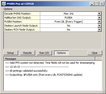
Driver Layout Menu: Options
|
Create Logfile |
Log settings / general / debug information to a log file in the current Project's LogFiles folder.
Filename convention of the logfile will be: "<Driver>.<System Name>.<Date> - <Counter>.log", where the counter field will increment automatically to make each log file unique. The option to create loggings is mainly for debug purposes; whenever you encounter problems and/or request help from QPS please submit these files to the support team. |
|
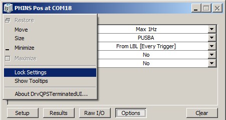
Lock Settings |
Enable to lock the user-interface settings of the Setup and Options menu, in order to prevent making changes by mistake.
|
|
Show Tooltips |
When hovering the mouse over the left column rows, you will get some more information. Disable if this becomes annoying...
|
|
Decode PHINS Position |
Reduce the number of decoded PHINS positions. Useful when the PHINS is broadcasting at high update rate, e.g. at 10Hz, but you don't want to store all these positions in the database. Note that this does not affect the decoding of the attitude message (Heading and Motion, HSATIT), only the position message (HSPOS). |
|
Halliburton SAS Output |
ZDA + PUSBA will output the NMEA $GPZDA message first, immediately followed by the corresponding $PUSBA message. This output combination is recommended (and only useful) when the ROV is in the water.
|
|
UDP Port |
When using the INS in UDP Transport Mode iXBlue recommends to setup input and output on different port numbers. Qinsy expects the incoming messages from the INS at the UDP port number as defined in the template setup.
So use this option to change the output port number
This option is not visible when using the serial version of the driver or when using the output-only variant of the network driver: in those case the output will always go to the port number as defined in the template setup. |
|
ZDA Output |
Select the desired output update rate for the NMEA ZDA message. Output of this message can only be triggered on time. |
|
GGA Output |
Select the desired output update rate for the NMEA GGA message. Output of this message can only be triggered on time. |
|
PUSBA Position |
Select the source and the desired output update rate for the $PUSBA message
|
|
Max Age |
Set the maximum age [in sec] for the last updated USBL trigger update time. The default value is 5 and the minimum value will be 2 seconds. When the last USBL trigger update time exceeds this age value, a $PUSBA message will be forced to output with the last known position.
This option is only available when PUSBA Position is set to From USBL [Every Trigger + MaxAge]. |
|
Output Datum |
The outputted position for the NMEA GGA or $PUSBA message will by default be on source datum (normally WGS'84). With this option the user may force the outputted position to be on Survey datum. |
|
Deskew Launch Node Output |
Select Yes in order to skew the time and position of the launch point node to the time of output (NMEA GGA message), using the current SOG and COG. Note that the SOG and COG depend on the Controller's Computation Setup, Object COG/SOG - Prediction Parameters Settings. The height value is not deskewed. |
|
Deskew ROV Node Output |
Select Yes in order to skew the time and position of the ROV node to the time of output ($PUSBA message), using the current SOG and COG. Note that the SOG and COG depend on the Controller's Computation Setup, Object COG/SOG - Prediction Parameters Settings. The height value is not deskewed. |
Dialog Buttons
|
Setup |
Invoke the Setup Menu |
|
Results |
Invoke the Results Menu |
|
Raw I/O |
Invoke the Raw Data Menu |
|
Options |
Invoke the Options Menu |
|
Clear |
The last 500 history messages are displayed in the message view. Use the Clear button to empty the list. |
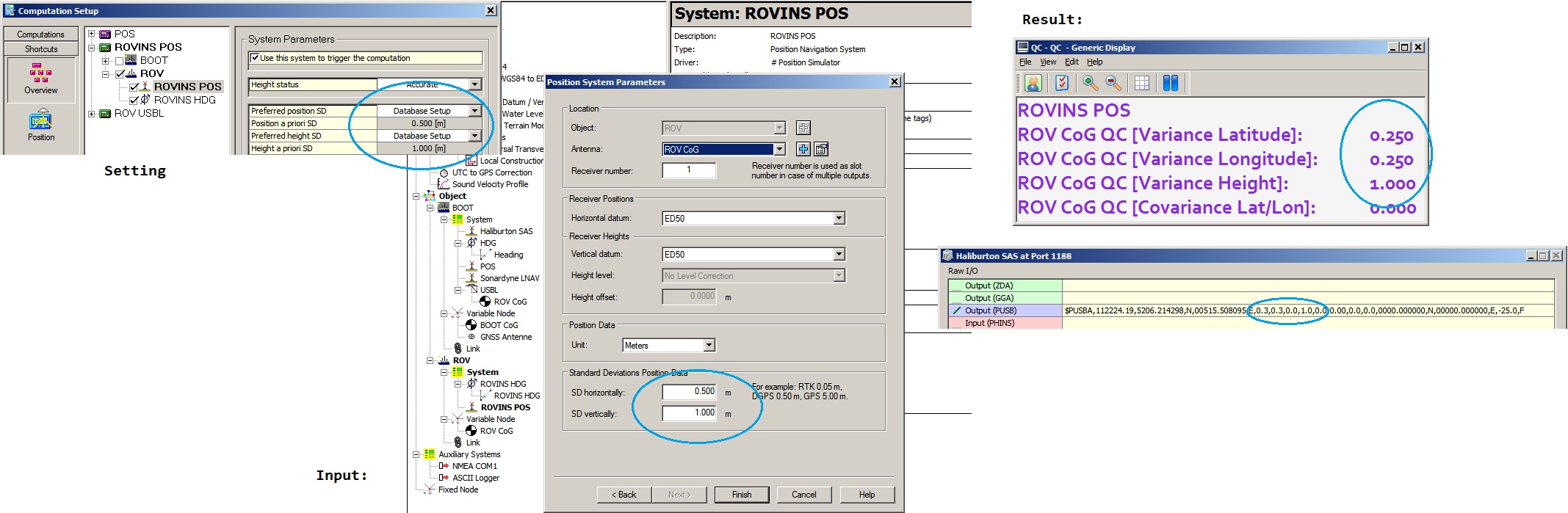
The a-priori SD values that are actually used depend on the Computation Setup settings:
-
the values entered in the database setup (Db Setup) and/or
-
the values coming from the system/observations and/or
-
the values as entered in the Computation Setup.
Examples
Setup with only a positioning system involved:
A-Priori From System:

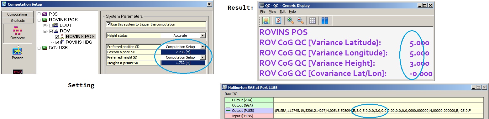
A-Priori From Template:
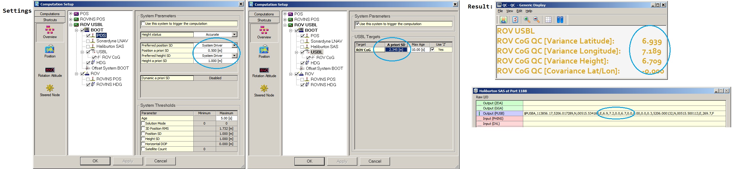
A-priori from computation:
Setup with USBL involved:
Additional Information
2024.11.12
-
Added option to create a logfile (mostly for debug purposes).
2020.06.15
-
Added option to change the UDP output port.
2018.10.09
-
Added option to select the datum of the output position: WGS'84 (default) or Survey Datum.
2018.01.29
-
Added option to set a maximum age for the USBL trigger when outputting the so-called PUSBA message.
2014.08.09
-
Modified Database Setup - Speed Log description.
Vertical speed is now used by Kalman Filter.
Added references to other related speed log driver manuals and Knowledge Base article on 'Howto Smooth Vessel and ROV tracks'.
2014.07.08.1
-
Added dedicated (serial) output driver ("iXSea PHINS+DVL Halliburton SAS (Output Only)") in case your setup does not need data from the PHINS.
2013.11.21.1
-
Added network driver version, supporting data input/output via LAN UDP network.
2010.12.31.1
-
Modifications in the $USBA output message:
Field 9 does now contain the depth variance value in meters, instead of hard-coded zero
Field 18 (Beacon Depth') does now contain a depth value, instead of height, meaning positive when underwater
2010.10.05.1
-
Label cosmetics in the message list
2010.09.14.1
-
User-interface modified
-
Setup Menu: Added ROV LBL Positioning Setup items
-
$PUSBA message: Output will be only on USBL trigger, ór on LBL Computation Trigger
-
NMEA ZDA Message now outputted on the whole (rounded) second
2009.04.10.1
-
Mistake in format description of the $PIXSE,HSPOS_message
2009.04.02.1
-
User-interface modified
-
$PUSBA message: Added option to output on USBL trigger
-
$PUSBA message: Added option to enter Age of Data entry manually
-
Added option to reduce decoding of the PHINS positions
|
$PIXSE,HSPOS_ |
ROV positioning information, calculated by the PHINS. |
|---|
Registry Options
-
The UDP Port number for the outgoing messages can be changed in the Options menu to the Port number from the template setup PLUS ONE.
If the input and output port setup on the INS (when in UDP Transport Mode) differs more than one then you can use the following registry key to change the value of one:
HKEY_CURRENT_USER\Software\QPS\QINSy\8.0\Drivers\DrvQPSTerminatedUIUDP\<YourDriverName>\Settings\PDS_OutputDeltaUDPPort -
As explained earlier, information in the Results menu will be displayed in red color when the age of the data exceeds five seconds.
This age limit (default 5 seconds) may be changed by modifying the registry key:
'HKEY_CURRENT_USER\Software\QPS\QINSy\8.0\Drivers\DrvQPSTerminatedUI\<YourDriverName>\Settings\ MaxAgeRawInput'.
-
Information in the Raw menu will be displayed in gray color when the age of the data exceeds five seconds.
This age limit (default 5 seconds) may be changed by modifying the registry key:
'HKEY_CURRENT_USER\Software\QPS\QINSy\8.0\Drivers\DrvQPSTerminatedUI\<YourDriverName>\Settings\ MaxAgeRawOutput'.
-
Change the following registry key (from '00' (default) to '01') if you also want to show the 'Lock Settings' and 'Show Tooltips' option in the Options menu:
'HKEY_CURRENT_USER\Software\QPS\QINSy\8.0\Drivers\DrvQPSTerminatedUI\<YourDriverName>\Settings\ ShowAllOptions'
-
Change the following registry key (from '01' (default) to '00') if you want to hide the three dark gray separator lines in the Setup menu:
'HKEY_CURRENT_USER\Software\QPS\QINSy\8.xx\Drivers\DrvQPSTerminatedUI\<YourDriverName>\Settings\ ShowSetupHeaders'