
Description
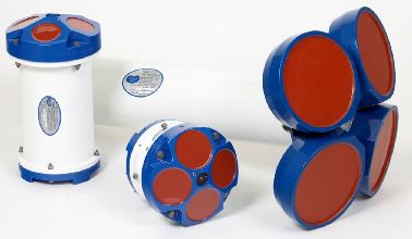
Driver with user-interface to decode bottom track velocity and direction from an ASCII output data ensemble from an RD Instruments (RDI) Acoustic Doppler Current Profiler (ADCP) that is configured as a Doppler Velocity Log (DVL).
The driver returns the horizontal velocity ( Speed ) along with its direction ( Angle ) (and/or Bearing True). When decoding the PD6 message, vertical velocity is also returned.
Three different ASCII output formats are supported:
For more information about these formats, see their entries in the Drivers Manual under Speed Log.
Driver Information
|
Driver |
RDI Doppler BottomTrack Speed (ASCII) (Active) |
Interface Type |
|
Driver Class Type |
Terminated |
|---|---|---|---|---|---|
|
No |
Input / Output |
Input |
Executable |
DrvRDIDopplerUI.exe |
|
|
Related Systems |
|||||
|
Related Pages |
|
||||
Decoding Notes
The RS-232 cable connection must have two-way direction, both receiving (Rx) and transmitting (Tx) data, since this driver will send commands to the unit and will receive data ensembles.
Database Setup
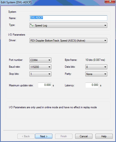
Make sure you set the baud rate as high as possible and that the FIFO buffers of the serial port are disabled (set as low as possible).
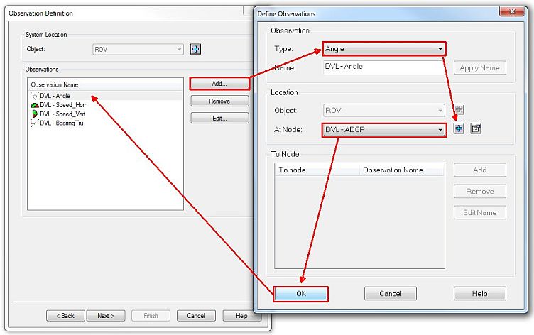
Add at least the following observations for following objects
-
Vessel
-
Angle
-
Speed (Horizontal Speed)
-
-
ROV
-
Angle
-
Speed
-
Vertical Speed
-
|
Output format |
Speed unit |
Angle unit |
Hor. Speed SD |
Angle SD |
Vert Speed SD |
|---|---|---|---|---|---|
|
PD6 |
m/s |
degrees |
0.1 |
5.0 |
0.1 |
|
Remote Cherry |
knots |
degrees |
0.1 |
5.0 |
|
|
VmDas NMEA |
knots |
degrees |
0.1 |
5.0 |
|
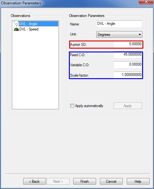
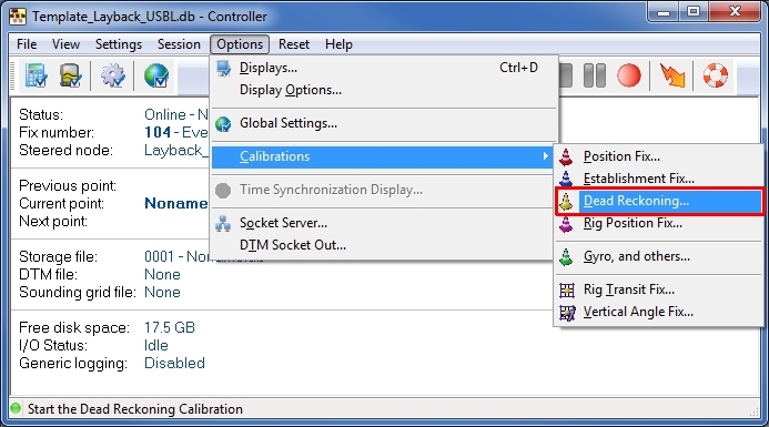
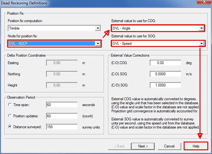
Values found during the (Dead Reckoning) calibration procedure need to be entered on this page, before commencing your survey to get the best real time results.
Online
Active Driver Interface
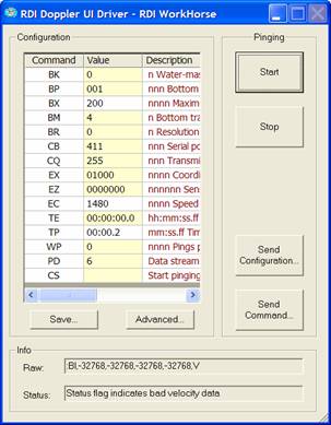
The user-interface can be found in the Windows taskbar:
The driver is active, meaning commands can be sent directly to the unit by the user.
Click on the RDI Doppler System in the taskbar to restore its dialog.
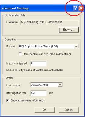
Use the Advanced button to browse for a configuration text file containing predefined commands. For more information on each setting, use the context sensitive help ('?' button).
For detailed descriptions regarding the commands displayed below, please refer to the COMMANDS AND OUTPUT DATA FORMAT document by RDI (P/N 957-6156-00 (March 2014))
-
Bottom Track commands
|
Command |
Value |
Range |
Unit |
Description |
|---|---|---|---|---|
|
BA |
30 |
1-255 |
counts |
Bottom Track (BT) filter setting |
|
BB |
160 |
1-9999 |
dm |
Band with selection 50%-25% boundary |
|
BC |
220 |
0-255 |
counts |
Bottom Track correlation filter |
|
BD |
0 |
0-999 |
ensemble |
Delay for BT detection after BT loss |
|
BE |
1000 |
0-9999 |
mm/s |
Error velocity |
|
BF |
0 |
1-65535 |
dm |
Depth guess (0=off) |
|
BI |
010 |
0-999 |
m |
Low / High gain mode boundary |
|
BK |
0 |
1-3 |
times |
Water mass Layers (0=disable) |
|
BP |
001 |
1-999 |
pings |
No. of pings for average |
|
BX |
030 |
10-65535 |
dm |
Max. expected depth for B.T. detection |
|
BL |
80, 160, 240 |
|
dm |
Water mass layers (if BK=0, do not care) |
|
BM |
5 |
4, 5 |
|
BT mode |
|
BN |
25 |
|
|
? |
|
BO |
25 |
|
|
BT filter setting |
|
BR |
0 |
0-2 |
|
0 = 4%, 1 = 2%, 2 = 1% depth resolution (effects ping rate) |
|
BS |
|
|
|
Start pinging |
|
BW |
00001 |
0-65535 |
|
No of water pings (do not care id BK = 0) |
|
BZ |
004 |
|
|
? |
-
Control system commands
|
Command |
Value |
Range |
Unit |
Description |
|---|---|---|---|---|
|
CB |
811 |
|
|
Baud rate
|
|
CF |
|
|
|
Flow control |
|
CQ |
? |
0-255 |
|
Transmit power
|
|
CR |
|
0, 1 |
|
1= retrieve factory settings |
|
CS |
|
|
|
Start pinging |
|
CX |
|
|
|
Low latency trigger
|
|
CZ |
|
|
|
Power down |
-
Environmental commands
|
Command |
Value |
Range |
Unit |
Description |
|---|---|---|---|---|
|
EX |
01000 |
|
|
Coordinate transformations/corrections |
|
EC |
|
1400-1600 |
m/s |
Speed of sound |
-
Timing commands
|
Command |
Value |
Range |
Unit |
Description |
|---|---|---|---|---|
|
TE |
00:00:00.20 |
|
hh:mm:ss.ss |
Time between ensembles (ensemble rate)
|
|
TP |
00:00.00 |
|
mm:ss.ss |
Time between individual pings within ensemble |
-
Water profile commands
|
Command |
Value |
Range |
Unit |
Description |
|---|---|---|---|---|
|
WP |
0 |
0-16384 |
pings |
No of water profile pings per ensemble
|
Calibration
Read the Help file for further instructions!
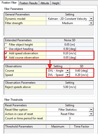
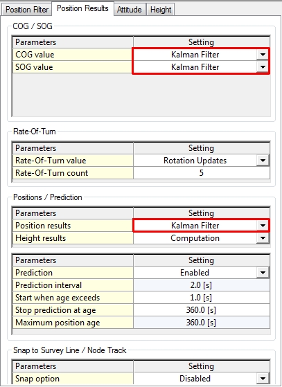
Computation Setup
The DVL is not visible in the equipment (devices) tree of the object.
The observations of the DVL can be selected via the tabs Position Filter and Position Results of the object (Vessel / ROV) it is installed on:
Smoothing Vessel or ROV Track
Please read the Knowledge Base document 'How-to Smooth Vessel or ROV Track'.
This document will give you additional information about the Computation Settings.
Alert Display
The Alert Display can be used to alert users on bottom track loss and exceeding the maximum speed.
When the bottom track is lost the driver will return a speed of approx -32768 m/s, and will not be used by the computation.
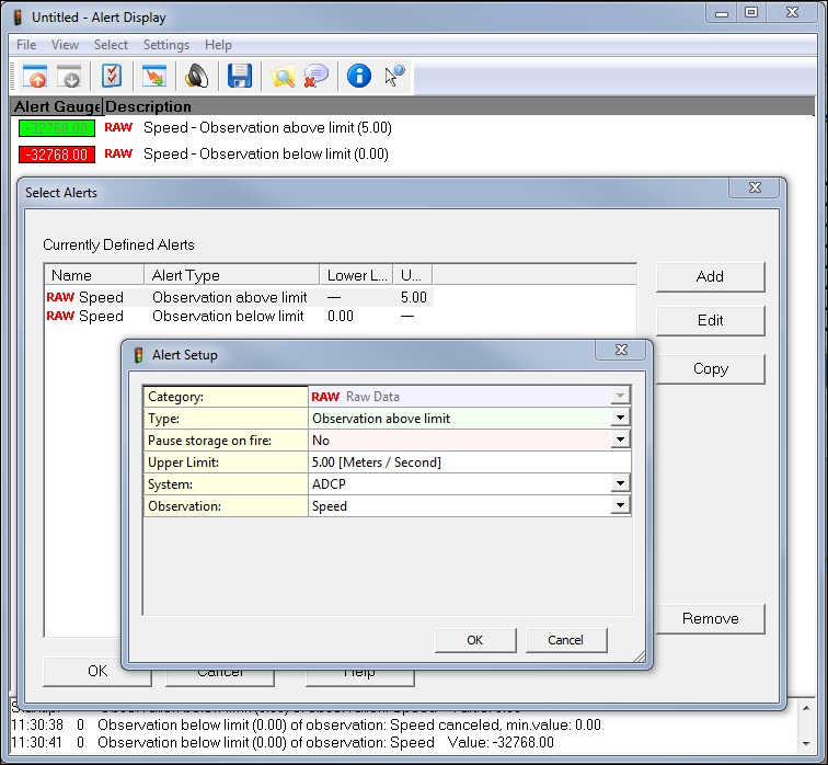
The Quality Indicators can also be used in the alert display. For more information follow the links under the driver description (on top).