
Description
Driver to decode a position (latitude, longitude and height), heading, attitude (roll and pitch) and heave from a NovAtel SPAN-SE GNSS/INS receiver, outputting the so-called DM-0360#inspva and DM-0360#heavea log format.
Further, the INS status, three velocity directions and the SD values for position, heading and attitude (roll and pitch, no heave) can be decoded as generic observations.
Driver Information
|
Driver |
NovAtel SPAN (#INSPVA + #HEAVEA Format) |
Interface Type |
Serial or Network |
Driver Class Type |
Terminated |
|---|---|---|---|---|---|
|
Yes |
Input / Output |
Input |
Executable |
DrvQPSTerminated.exe
|
|
|
Related Systems |
|
||||
|
Related Pages |
|
||||
Interface Type
This driver supports both serial as well as network UDP and TCP communication.
For the network driver please select the driver name that starts with "Network (UDP) - NovAtel..." or "Network (TCP) - NovAtel..."
Configuring the device
In order to enable the correct messages, create a connection to the device on the used interface (f.i. with I/O tester). Each message type needs to be individually activated.
The following example enables #INSPVA, #INSCOV, #HEAVE and #TIME messages and saves the configuration. (Unwanted message types may be omitted):
unlogall
log inspvaa ontime 0.04
log inscova ontime 0.04
log heavea onnew
log timea ontime 1
saveconfig
Decoding Notes
-
The GPS time fields from the message are decoded, converted to UTC and used for time-stamping in case your template setup supports Time Synchronization.
Therefore it is important to set the correct UTC to GPS correction in your template setup (17 seconds as of January 2017). -
The CRC32-bit checksum is by default decoded and used to check the data integrity. If the checksum fails, no data will be decoded, unless you use command-line parameter 'NOCS' (advanced user only!).
-
The INS Status text (data field # 12) is decoded as number as defined in the Inertial Solution Status Table of the NovAtel manual:
|
Text |
Value |
Description |
|---|---|---|
|
INS_INACTIVE |
0 |
IMU logs are present, but the alignment routine has not started; INS is inactive. |
|
INS_ALIGNING |
1 |
INS is in alignment mode. When in this status, the user can move to initiate the kinematic alignment or send a SETINITAZIMUTH command. This status also shows if the IMU status is not valid. The IMU status is given in the RAWIMU and RAWIMUS logs. |
|
INS_SOLUTION_NOT_GOOD |
2 |
The INS solution is still being computed but the azimuth solution uncertainty has exceed 2 degrees. The solution is still valid but you should monitor the solution uncertainty in the INSCOV log. You may encounter this state during times when the GPS, used to aid the INS, is absent. |
|
INS_SOLUTION_GOOD |
3 |
The INS filter is in navigation mode and the INS solution is good. |
|
INS_BAD_GPS_AGREEMENT |
6 |
The INS filter is in navigation mode, and the GPS solution is suspected to be in error. This may be due to multipath or limited satellite visibility. The inertial filter has rejected the GPS position and is waiting for the solution quality to improve. |
|
INS_ALIGNMENT_COMPLETE |
7 |
The INS filter is in navigation mode, but not enough vehicle dynamics have been experienced for the system to be within specifications. |
Database Setup
-
In order to decode PPS (Time Synchronization) from the TIMEA message, add a Time Synchronization system to your template and select the driver NovAtel SPAN-CPT (#INSPVA Telegram).
-
In order to decode the position from the DM-0360#inspva message, add a Position Navigation System to your template and select the driver "NovAtel SPAN (#INSPVA + #HEAVE Format) (With UTC)".
It is important to select for the Horizontal and Vertical datum on the second wizard page 'WGS84' datum. -
In order to decode a heading from the DM-0360#inspva message (Azimuth field), add a Gyro and Compass System to your template and select the driver "NovAtel SPAN (#INSPVA + #HEAVE Format) (Heading)".
Select the same I/O parameters as for the defined Position Navigation System above. -
In order to decode the attitude from the DM-0360#inspva and/or DM-0360#heavea message, add a Pitch, Roll and Heave Sensor System to your template and select the driver "NovAtel SPAN (#INSPVA + #HEAVE Format) (R-P-H)".
Select the same I/O parameters as for the defined Position Navigation System above.
It is important to select the Slot on the 2nd wizard page. There will be three choices:
|
P/R ONLY |
Driver will only decode the pitch and roll from the inspva message. Other messages are ignored.
|
|---|---|
|
HEAVE ONLY |
Driver will only decode the heave from the heavea message. Other messages (inclusive the inspva) are ignored.
|
|
P/R/H |
Driver will decode the pitch and roll from the inspva message and the heave from the heavea message.
|
-
A DM-0360#heavea message is immediately followed by an DM-0360#inspva message, but both will have their own time-stamping. This means that a roll-pitch observation update has a different time-tagging than a heave observation update (although this can be less than 5 msec).
So because the heave has its own timing, the user may adjust the setup in order to cover the following scenarios: -
Scenario 1
User may define two motion systems: One with Slot P/R ONLY and one with Slot HEAVE ONLY
So pitch/roll observations will have their own time-stamp, and heave observation has its own time-stamp.
In the Computation Setup online the user should select on the Attitude tab for the Pitch and Roll the first defined system,
and on the Height tab the user should select the second defined system for the Height.
Timing will be accurate because that is taken care of by the Computation.
For this scenario the Node (Lever Arm) must be Center of Gravity, so any offset correction must take place inside the NovAtel unit-
Scenario 2
User will define only one motion system, with Slot P/R/H. This makes the setup simple.
Pitch/roll and heave observation will have the same timestamp (from the actual roll-pitch observation update).
User is aware of that heave timing is e.g. 5 msec out, but it may be not that critical for him.
User may even enter a Heave delay (positive) in the template setup, assuming that the 5 msec is more or less constant.
Theoretically this latter setup will be as accurate as a setup under scenario 1)
-
-
In order to decode separately the INS Status and/or the Velocity fields for monitoring these values, add a Miscellaneous System to your template, and select the driver "NovAtel SPAN (#INSPVA + #HEAVE Format) (Status and Velocity)".
Select the same I/O parameters as for the defined Position Navigation System above.
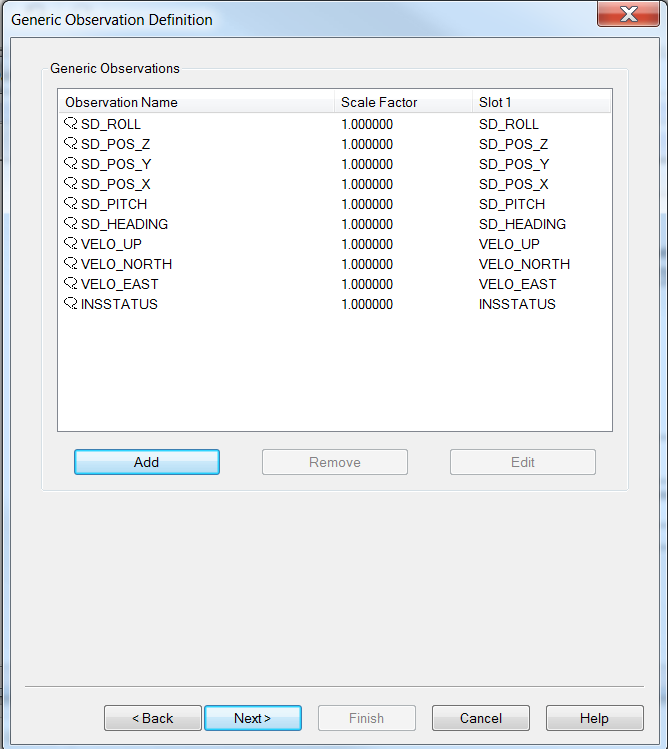
On the 2nd wizard page, the observations can be added:
INSSTATUS
Add a generic observation. Name it e.g. 'Ins Status', and enter for Slot 1: 'INSSTATUS'.
Velocity
For the Velocity fields, add three more Generic Observations and name these e.g. 'Velocity North', 'Velocity East' and 'Velocity Up'. Enter for the Slot 1 Id's: 'VELO_NORTH', 'VELO_EAST' and 'VELO_UP'.
SD
For the SD fields, add six more Generic Observations and name these e.g. 'SD position X', 'SD position Y', 'SD position Z', 'SD roll', 'SD pitch', and 'SD heading'. For the slot ID's use respectively SD_POS_X, SD_POS_Y, SD_POS_Z, SD_ROLL, SD_PITCH and SD_HEADING
Note
It is important that all Slot Id's are entered in capitals.
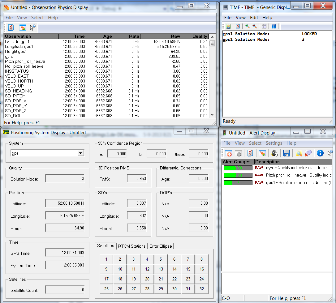
Online
For a Position Navigation System you can monitor the INS Status as Solution mode in a Position System Display, as RAW DATA Positioning item Solution Mode in a Generic Display, or as Raw Alert 'Solution Mode outside limit' in the Alert Display.
For a Heading, roll and pitch observation or the four Generic observations you can monitor this value as Quality indicator in an Observation Physics Display, or as Raw Alert 'Quality indicator outside limit' in the Alert Display.
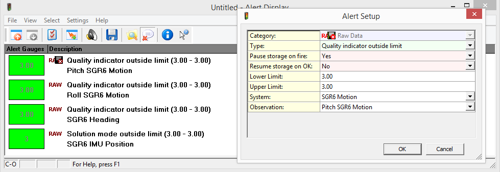
Use the Alert Display
When heading, roll and pitch Quality indicators are -1 the data is not used by Qinsy.
It is advisable to have the Alert Display stop the recording based on the Lower and Upper Limit value of 3.
You'll need Skype CreditFree via Skype