
Description
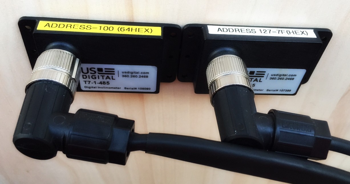
Driver to decode data from a US Digital T7 Inclinometer, a solid state absolute inclinometer that measures tilt angles over a full 360 degrees range in a single axis, so one sensor can be used as pitch or as roll sensor.
Multiple sensors can be 'daisy-chained', which means that the sensors are connected to each other in a chain, which simplifies installation.
One chain is connected to one COM port. Up to 32 T7 sensors can be connected in one chain, where each sensor should have its own unique address.
Typical application for using this rugged, compact and all-weather proof sensor is to mount it on dredging heads, excavators, crane arms, etc. in order to get the orientation of the object.
Driver Information
|
Driver |
US Digital T7 Inclinometer (Pitch or Roll only) |
Interface Type |
Serial |
Driver Class Type |
API (T7User.dll required) |
|---|---|---|---|---|---|
|
No |
Input / Output |
Input / Output |
Executable |
DrvQPSFreeBase.exe USDIGITAL_T7 |
|
|
Related Systems |
|||||
|
Related Pages |
|
||||
Decoding Notes
-
Every cycle the driver interrogates all connected T7 units for data. Therefore the serial COM port wiring must be bi-directional.
-
The data from the T7 does not contain timing information, so time-stamping of the data will be done by the driver upon arrival at the COM port.
-
The data from the T7 does not contain any quality and/or accuracy information. The driver will mis-use the roll/pitch observation quality indicator and put the used address id value in it.
-
The initial behavior of the sensors should be controlled using US Digital T7 software. Most important setting of this software is to reset the start angle to zero. The user can also set the desired damping rate (time for averaging multiple samples).
Interfacing Notes
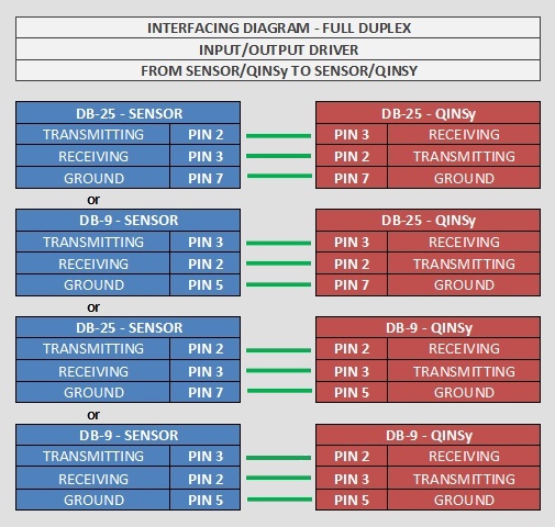
The driver will interrogate each connected sensor, therefore one should take the following bi-directional wiring diagram into account when using I/O cables and connectors:
Database Setup
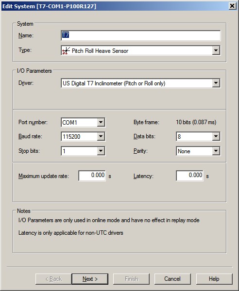
Add a Pitch, Roll and Heave Sensor System to the template and select driver "US Digital T7 Inclinometer (Pitch or Roll only)".
Set the correct IO parameters.
If you leave the maximum update rate at zero, the driver will interrogate the sensor as fast as possible, but the actual update rate depends on the used hardware (Computer specs, OS, Serial card) and the number of sensors connected.
For example if you only want to have a maximum of ten readings per second, enter for the maximum update rate 0.100 s.
There are no known issues about latency so leave the latency field at zero (although the sensor's damping rate may have an influence on the latency).
On the second wizard page three items are important: the Slot Id, the Roll convention and the Pitch convention.
The Slot id will tell the driver what kind of observation should be assigned to which sensor. Please use the following convention:
|
PxxxRyyy |
Sensor with address 'xxx' will be used for pitch and sensor with address 'yyy' will be used for roll. |
|
Pxxx |
Sensor with address 'xxx' will be used for pitch. No roll expected for this system. |
|
Ryyy |
Sensor with address 'yyy' will be used for roll. No pitch expected for this system |
-
Per system you can assign one (roll or pitch) or two sensors (roll and pitch)
-
Use for address 'xxx' and/or 'yyy' any valid address (1-100, or 127)
-
There is no heave
For example, the screen capture shows a system with Slot P100R127. This means that for the pitch observation the driver will use the tilt angle from the sensor with address 100, and for the roll observation it will use the tilt angle from the sensor with address 127.
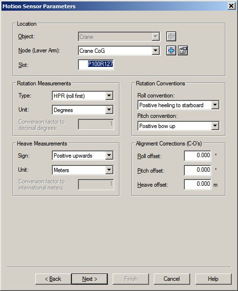
About the Roll convention: change the default setting to 'Positive heeling to port' when you are facing the connector, looking in the direction from aft to bow.
For the Pitch convention change the default setting to 'Positive bow down' when you are facing the connector, looking in the direction from port to starboard.
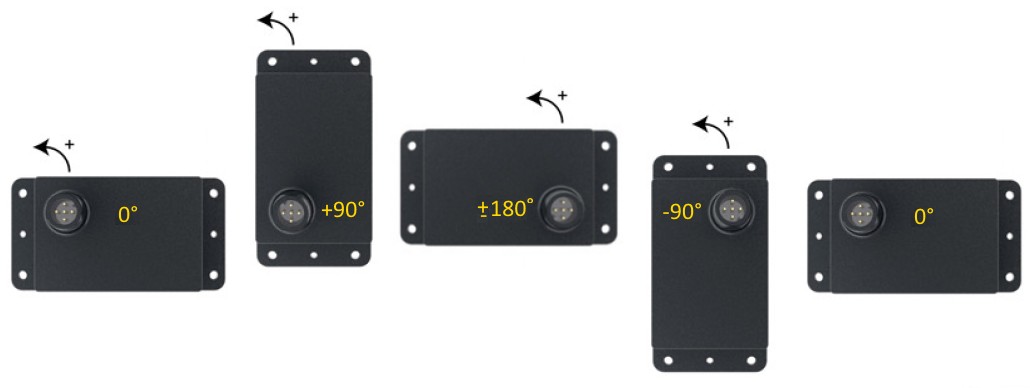
The above yellow tilt angle is the raw value as reported by the sensor.
Online
You can use an Observation Physics Display to monitor whether data is coming in, how fast the data is coming in, and what the decoded values are.
The Raw data column shows the decoded value straight from the sensor.
The Corrected column shows the value after applying the sign convention and possible alignment corrections as defined in your system setup.
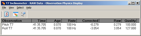
Notice the Quality indicator column: the number represents the address of the sensor that has been interrogated.
Additional Information
-
The accuracy of the tilt angle is 0.1° (as stated by US Digital).
-
It is recommended not to define sensors in your system setup which are physically not connected. Note that every cycle all defined sensors will be interrogated by the driver and when there is no response from one of them, it will introduce a noticeable delay: this will result in a slower update rate for all other connected sensors.
The default delay time when there is no response is 150 milliseconds, but may be decreased by an advanced user by modifying the following registry key:
HKEY_CURRENT_USER\Software\QPS\Qinsy\8.0\Drivers\DrvQPSFreeBase\Settings\TimeOut
Valid values are between 2 and 300 milliseconds.
Drivers IO Notes
-
ACTIVE
This command line option will allow the user to reset the start angle to zero. Every time you reset the system from the Controller (pull-down menu Reset System I/O...) a command will be sent to all connected sensors to set the angle in the current orientation to zero.
(The same action that you can do using the US Digital T7 software, as mentioned in the Decoding Notes.)