Description
The Innomar SES200 driver can be used to decode the following data from the unit:
-
Depth for both channels
-
Motion (Roll, Pitch, Heave)
-
Heading
-
Pressure (external pressure sensor)
-
Sub Bottom Profiling data
Sub bottom profiling data can be viewed in Qinsy in the Sub Bottom Profiling display since version 8.15.0. When a sub bottom profiler system is configured in the template database, the sub bottom profiling data will be recorded in the database. The recorded data can be exported to the SEG-Y format for processing in seismic software.
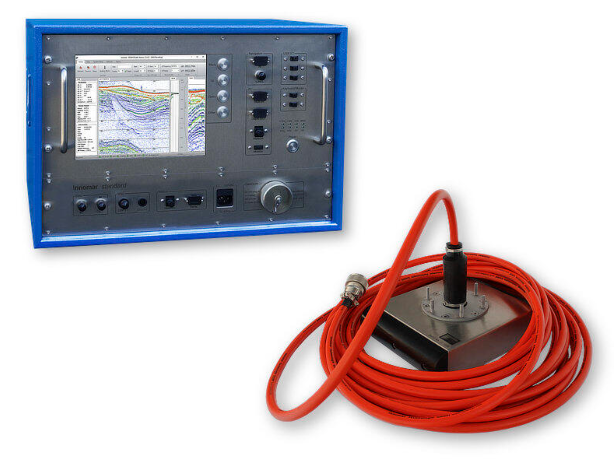
SES-2000 standard parametric sub-bottom profiler
NOTES
-
Sidescan not supported
Driver Information
|
Driver |
Innomar SES2000 |
Interface Type |
Network |
Driver class type |
QpsCountedTcp |
|---|---|---|---|---|---|
|
No |
Input / Output |
Input |
Executable |
DrvQPSCountedTcp.exe |
|
|
Related Systems |
|
||||
|
Related Pages |
|
||||
Qinsy Configuration
Database Setup
In general the setup for this driver is equal to the setup of any driver in Qinsy; fill in the IP-address and port number on which the unit can be reached (refer to the manufacturer's documentation for more information) and set the settings related to the system you are configuring. There are some exceptions where specific settings are required. These systems are described in the following paragraphs.
Singlebeam Echosounder
The Innomar SES2000 reports detected depth for (up to) two channels. These depths can be brought into Qinsy by adding a singlebeam echosounder system to your setup. The depths decoded by this system can be stored in a DTM and/or grid file.
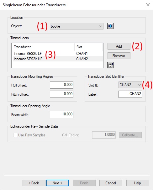
On the 'Singlebeam Echosounder Transcuders' page of the singlebeam echosounder setup wizard you can select which depth(s) you want to read.
-
Select the object on which the transducer is mounted (normally your vessel) as 'Object'.
-
Click the 'Add' button to add a transducer.
-
In the select nodes dialog, either select an existing node for the transducer, or add a new node.
For optimal results, the location of the node should be the exact phase center of the transducer for the chosen channel. Refer to the manufacturer's documentation for information on the exact phase centers of the different channels.
-
-
A line with the name of the transducer node has been added to the list box. Select the new line.
-
Choose which channel to decode by selecting the Slot ID. "CHAN1" means channel 1 will be used. Similarly "CHAN2" will use channel 2.
-
Enter the appropriate values for the remaining settings (none of these are specific to this driver/system).
Underwater Sensor
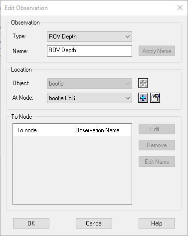
If an external pressure sensor is connected to your system, you can bring this reading into Qinsy by adding an Underwater Sensor system.
-
On the 'Observation Definition' page of the wizard, click Add.
-
In the resulting 'Define Observations' page
-
Select 'ROV Depth' as Type.
-
Give it any name you like.
-
Select (or create) the node where the external pressure sensor is located.
-
Click OK (there is no need to make any changed to the 'To node' portion of the dialog)
-