
This page will describe additional information about object types which can be chosen when setting up a template database.
On this page:
Object types within Qinsy
Within Qinsy the following object types exist:
|
Object Type |
Description |
Origin |
Addable1 |
Surface2 |
Sub Surface3 |
Systems4 |
Filters5 |
Priorities6 |
Remark |
|---|---|---|---|---|---|---|---|---|---|
|
VESSEL |
Vessel |
UKOOA P2/94 |
|
|
|
|
|
|
|
|
SURVEY_VESSEL |
Survey vessel |
Qinsy |
|
|
|
|
|
|
Virtually the same as OBJ_VESSEL.
|
|
ROV_TOWHEAD |
ROV, AUV, towhead |
Qinsy |
|
|
|
|
|
|
|
|
TOWED_FISH |
Towed fish |
Qinsy |
|
|
|
|
|
|
|
|
LINK_TOOL |
Link tool |
Qinsy |
|
|
|
|
|
|
May exist above & below the water surface. |
|
DREDGING_TOOL |
Dredging tool |
Qinsy |
|
|
|
|
|
|
May exist above & below the water surface. |
|
BENCHMARK |
Benchmark |
Qinsy |
|
|
|
|
|
|
Stand alone (object) location on the seabed or a range-bearing target |
|
GUN_ARRAY |
Gun array |
UKOOA P2/94 |
|
|
|
|
|
|
|
|
OBJ_STREAMER |
Steamer |
UKOOA P2/94 |
|
|
|
|
|
|
Not addable in DbSetup
|
|
BUNDLE |
Pipe bundle |
Qinsy |
|
|
|
|
|
|
|
|
ANCHOR |
Anchor |
Qinsy |
|
|
|
|
|
|
Not addable in DbSetup only available online |
|
EARTH |
Earth-fixed |
UKOOA P2/94 |
|
|
|
|
|
|
Pseudo object which is implicitly added when defining a fixed node |
Object types in this category:
1 = may be added in DbSetup
2 = are considered surface objects
3 = are considered subsurface objects
4 = may contain systems
5 = have their own Kalman & speed filters
6 = have attitude/height priority settings
Vessel and Survey Vessel
Template database setup
As the vessel and the survey vessel are using the same object type, they will be descripted together.
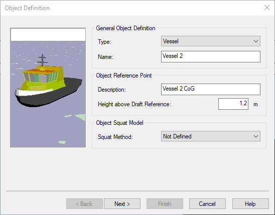
This object type should be used for all objects above or on the water surface. Examples of this are:
-
Surface Objects.
-
Vessels
-
Pontoons
-
Barges
-
Trailing Suction Hopper dredger (TSHD) vessel
-
Cutter Suction Dredger (CSD) pontoon/vessel
-
Backhoe Dredger (BHD) barge/pontoon/vessel
-
Split Hopper Barges (SHB) barge/vessel
-
Pipe Lay Vessel
-
-
ASV's (Unmanned Surface Vehicle ).
-
UAV (Drones).
-
AUV.
This object type could also be used for an AUV. In that case the depth sensor needs to be used as a draft sensor in order to compute the water level height.
This object is considered to be a surface object and systems can be added to the object.
It can have its own Kalman & speed filter, as attitude & height priorities.
Which info is needed to calculate position? It needs its own positioning system (GNSS/Total Station/Range-Bearing/LBL/USBL/ect) to calculate the position (X,Y). When having an accurate positioning (RTK/TotalStation) it can also calculate the height of the object (Z) otherwise a Water Level height (Predicted Tide/Tide Gauge/Mean Water Level model) needs to be used.
In all scenario's the Center of Gravity (CoG) its Height Above Draft Reference (HADR) and the draft of a vessel are important to calculate the appropriate node locations and transducer depth(s) of the echosounders on the vessel object and linked (child) objects.
More information about how to set up this can be found in the How-to RTK Height as Tide
Online
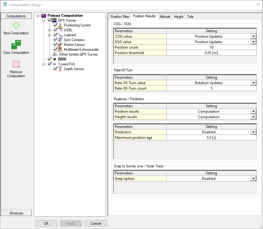
In the Computation Setup when selecting the Vessel (Surface Object) the following options become available:
-
Position filters: Under this tab filters can be selected to smooth the track of the positioning, using a Kalman Filter. More information can be found in the How-to Smooth Vessel or ROV Track
-
Position results: Under this tab the settings can be found for for setting how the object node positions are interpolated and predicted following the position updates or Kalman Filter updates at a triggering system update time.
-
Attitude: Under this tab the priorities for the Heading and Pitch and Roll calculations can be selected. For instance using the COG instead of the Gyro Compass Systems.
-
Height: Under this tab the settings for the Height interpolation and the settings for the draft (Manual or using a draft sensor) and the squat (When being setup in the Object Definition in the Template Database) can be found here.
-
Tide: Under this tab settings for setting up Tide van be found. More information can be found in:
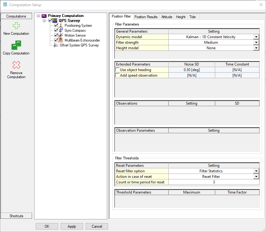
Tip
When more information is required about certain options in the Computation Setup, press the key F1 in the Computation Setup Dialog to open the Offline help.
ROV, AUV and Towhead
Template database setup
A remote controlled object is defined by this type.
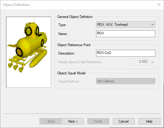
This object type should be used for rigid objects sub surface. Examples of this are:
-
ROV's
-
Crawlers
-
Trenchers
-
AUV's
This object is considered to be a subsurface object and systems can be added to the object.
It can have its own Kalman & speed filter, as attitude & height priorities.
Which info is needed to calculate position?
Under water object are generally positioned by:
-
USBL system installed on the vessel outputting calculating the dX, dY and dZ or Depth result of a beacon ID linked to a node on the ROV object
-
Use Depth (most used as its more stable then Use-Z)
-
Note: FQI-267 - Getting issue details... STATUS
-
-
Use Z relative to node selected (reference point CoG/CRP/Transducer)
-
-
INS
-
Lat Long Position + Depth
-
In many cased the INS is then fed with positions from Qinsy
-
iXblue Haliburton SAS driver
-
iXblue STD BIN
-
Generic NMEA of a Node
-
-
Advised to interface Depth sensor directly INS to prevent delays
-
-
The ROV object needs:
-
Its own (underwater) positioning system (USBL-beacon/INS) to calculate a position. As height component one can choose to Use-Z/Depth/Height.
-
An Surface Vessel to be present in the setup. Its used for the calculation of the (Mean Actual) Water Level.
More information about how to set up an ROV can be found in the How-to Tow Fish or ROV
Online
In the Computation Setup when selecting the ROV the following options become available:
-
Position filters: Under this tab filters can be selected to smooth the track of the positioning, using a Kalman Filter. More information can be found in the How-to Smooth Vessel or ROV Track .
-
Position results: Under this tab the settings can be found for for setting how the object node positions are interpolated and predicted following the position updates or Kalman Filter updates at a triggering system update time.
-
Attitude: Under this tab the priorities for the Heading and Pitch and Roll calculations can be selected. For instance using the COG instead of the Gyro Compass Systems.
-
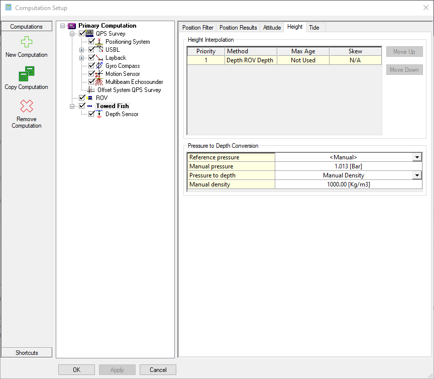
Height: Under this tab the settings for the Height interpolation and the settings for the Pressure to Depth Conversion (When a pressure sensor has been added to the object in the template database) can be found here.
-
Tide: Under this tab settings for setting up Tide van be found. More information can be found in:
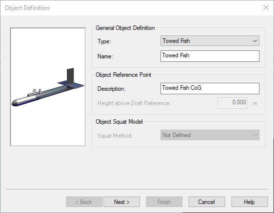
Towed Fish
Template database setup
An object towed behind a vessel.
This object type should be used for towed bodies which are located below the water surface. Examples of this are:
-
Side Scan Sonar fish.
-
Remotely Operated Towed Vehicle.
This object is considered to be a subsurface object and systems can be added to the object.
It can have its own Kalman & speed filter, as attitude & height priorities.
Which info is needed to calculate position?
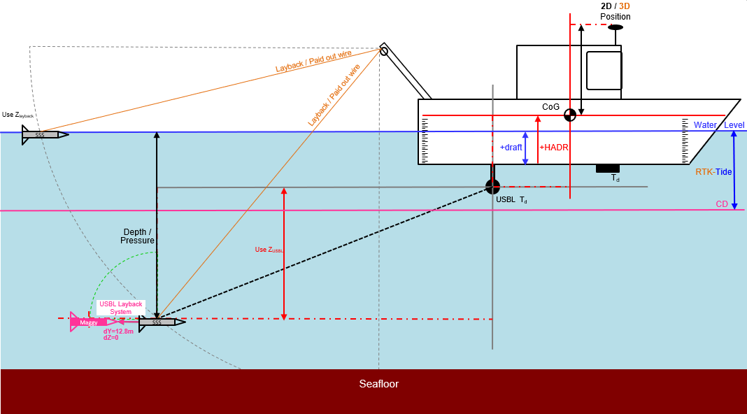
-
Always needs a Surface Object (Vessel/Survey Vessel) for the calculation of the (From - To) Nodes and determining the water level.
-
A Layback system (Paid out wire)
-
Use Depth observation
-
When Depth Observation is available it will use Depth = 0 and skim on the water level
-
-
USBL system dX, dY, dZ or Depth
-
Use Z
-
Use Depth
-
-
USBL Layback system when its piggybacked behind an existing layback system
More information about how to set up a Towed Fish can be found in the How-to Tow Fish or ROV
Online
In the Computation Setup when selecting the Towed Fish the following options become available:
-
Position filters: Under this tab filters can be selected to smooth the track of the positioning, using a Kalman Filter. More information can be found in the How-to Smooth Vessel or ROV Track.
-
Position results: Under this tab the settings can be found for for setting how the object node positions are interpolated and predicted following the position updates or Kalman Filter updates at a triggering system update time.
-
Attitude: Under this tab the priorities for the Heading and Pitch and Roll calculations can be selected. For instance using the COG instead of the Gyro Compass Systems.
-
Height: Under this tab the settings for the Height interpolation and the settings for the Pressure to Depth Conversion (When a pressure sensor has been added to the object in the template database) can be found here.
-
Tide: Under this tab settings for setting up Tide van be found. More information can be found in:
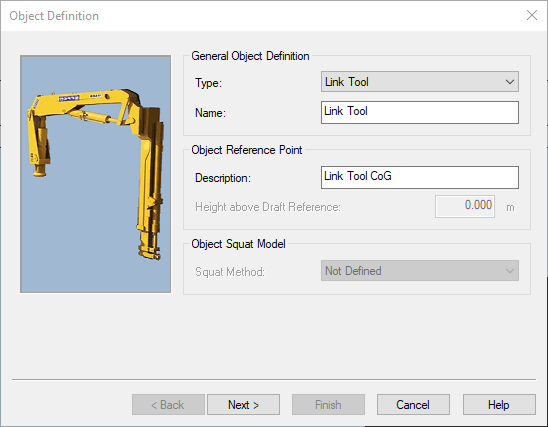
Link Tool
Template database setup
An object used for linking Child object to a Main/parent object
This object type should be used for objects which are attached to another object by a rotation point and follow the movement/attitude of their parent object. Examples of this are:
-
Dredging
-
Trailing Suction Hopper Dredgers (TSHD) tools - TSHD - Object Linking
-
Port Suction Pipes
-
Starboard Suction Pipes
-
Crane house - Boom
-
-
Backhoe Dredgers (BHD) tools - BHD - Object Linking
-
Cabin / Crane house (positioned with horizontal angle or Heading)
-
Boom
-
Stick
-
Artic
-
Bucket (Dredging Tool)
-
-
Cutter Suction Dredgers (CSD) tools - CSD - Object Linking
-
Ladder
-
Anchor Booms
-
Crane house - Boom
-
-
Excavator tools
-
Tracks
-
Boom
-
Stick
-
Artic
-
Bucket (Dredging Tool)
-
-
-
Survey
-
A-Frame
-
David crane
-
Moon pool bracket/trolley (at fixed location, but with its own AHRS sensor)
-
Over the Side Mount (OSM) / Survey Pole
-
Rotating platform/bracket
-
Norbit STX 360º
-
-
-
ROV
-
Manipulator Arms
-
Fold-able arms with survey sensors
-
-
Pipe Lay Vessel
-
Stinger parts
-
Crane house - Boom
-
Which info is needed to calculate the position?
A Link Object is considered to be a surface and subsurface object and systems can be added to the object.
It can not have its own Kalman & speed filter, but it has its own Attitude priorities.
The object linking functionality in QINSy is designed to calculate the exact position and attitude of multiple objects that are physically connected with a swivel joint or a hinge.
For example a crane comprises a cab (Link Tool) where the operator sits, a boom (Link Tool) that is hinged to the cab, a stick (Link Tool) that is hinged to the boom (Link Tool), and a bucket (Dredge Tool) that is attached to the stick via a hinged or swivel joint.
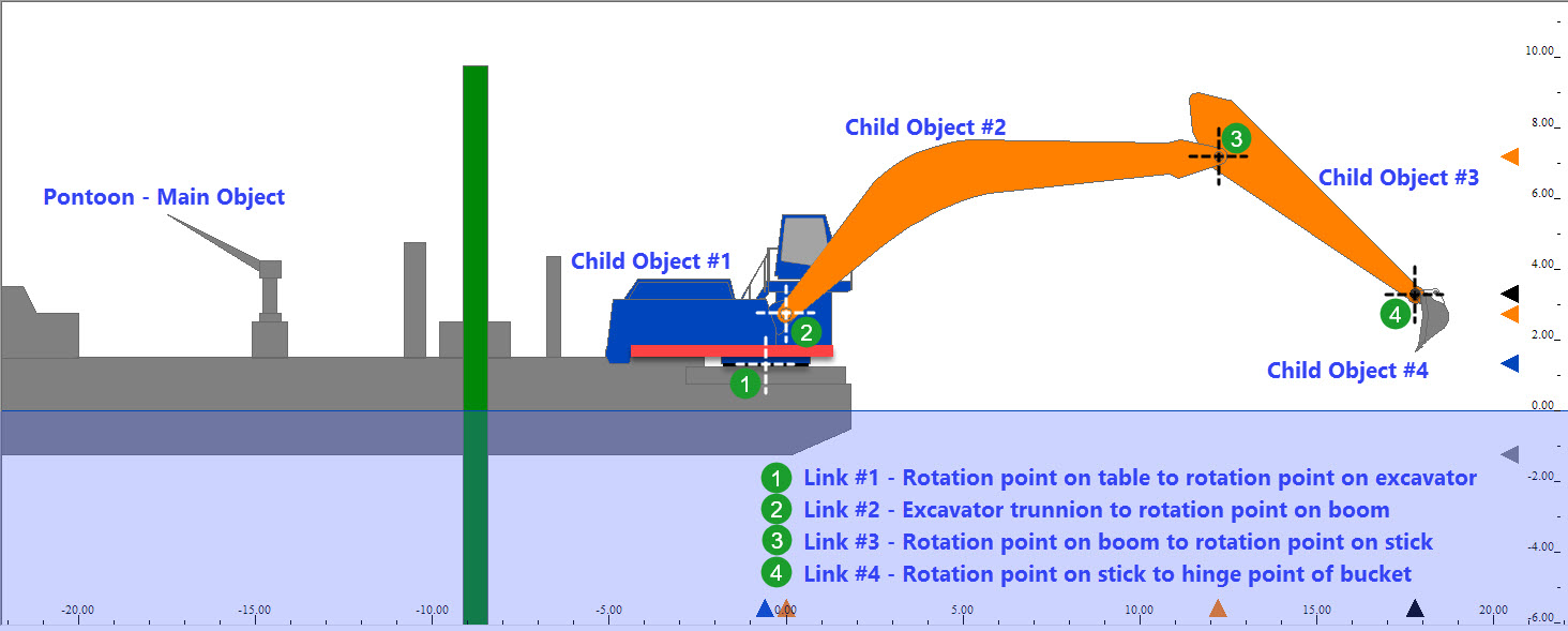
Each component is an 'object'. The idea is to "link" one object to another or in other words, to establish a relationship between the object pieces making up the whole. There is usually a main object (Vessel) which is fully positioned and oriented, i.e. the main object should have its full position and attitude known. Since the other objects of the whole bear a relationship to the main object, you only need an angular observation on the axis of the joint in order to link one object to another. The angle observation can be either an absolute or a relative observation. This is akin to creating a parent-child relationship, i.e. the linked object position is dependent on the main object (filtered) position.
When using an echosounder (MBES/SBES/ect) on a Link Tool, Qinsy will use the calculated transducer depth below the waterline, to determine the correct speed of sound from the active Sound Velocity Profile (SVP) for ray tracing and it will store the transducer depth in the QPD.
Underwater sensors on Link Tools
Underwater sensors systems like draft sensors should in the (Template DB) Setup be added to the main object.
Sound Velocity Sensors can be added to link tool and can be used for the echosounder (MBES/SBES) on that same Link Tool.
Example:
A vessel with a moon pool and positioning a frame/bracket/trolley lowered into the moon pool to a fixed position. The "Trolley" is setup as a linked tool, because its at a "fixed" rotation point in the moon pool. The "Trolley" is equipped with a MultiBeam EchoSounder (MBES) and its own Attitude Heading Reference Sensor (AHRS) because there is some degrees of freedom and we want to want to prevent artifacts.
Because vessel draft sensors are:
-
heavily filtered,
-
not always well maintained (marine growth),
-
not always available for survey input and/or at unknown locations.
Its the easiest to add a Depth/Draft sensor on the "Trolley" and use it as a draft sensor for your survey setup for the vessel.
The location of a node on a Link Tool can change within the Master (Vessel) object frame and therefor cannot be used as a node for the draft observation on the Vessel Object, by design.
To be able to use the Depth/Draft observation for the Vessel Draft, the system needs to be added on the Vessel object with a node to indicate its location.
More information about object linking can be found in: How-to Object Linking
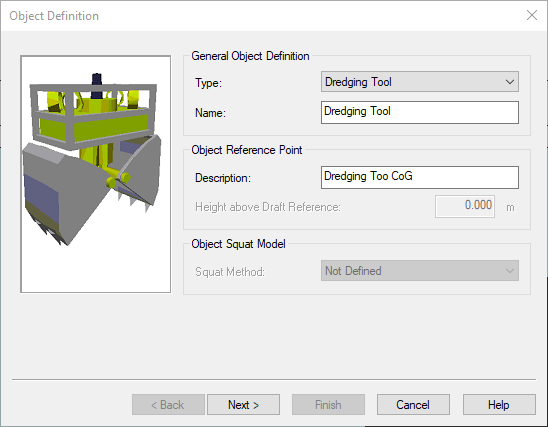
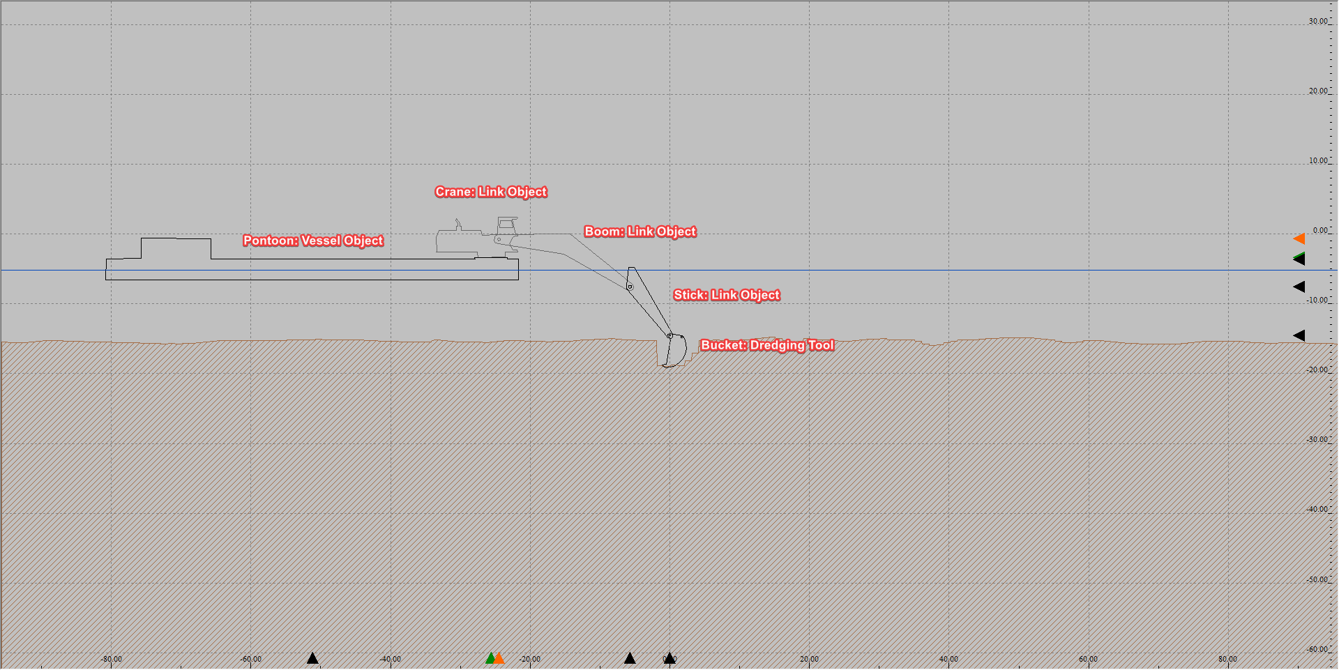
Dredging Tool
Template database setup
An object which is connected to a vessel and which is used for dredging purposes.
This object type should be used for objects which function as a dredging tool. Examples of this are:
-
Cutter head as used by a Cutter Suction Dredgers (CSD).
-
Trailing drag head(s) as used by a Trailing Suction Hopper Dredger (TSHD).
-
Bucket as used by a Backhoe Dredger (BHD).
-
Buckets as used by a bucket dredger.
This object is considered to be surface and subsurface objects and systems can be added to the object.
It can have its own Kalman & speed filter, as attitude & height priorities.
Furthermore is it capable to modify the content of a sounding grid file.
Which info is needed to calculate position?
-
Linked objects
Is getting its position via a Linked object between the Object with its own positioning system and Link Tool objects (Child objects) in between. The position of the Dredging Tool is then being calculated through the offsets of the linked nodes and angles. -
USBL dX, dX,dZ
-
USBL dX,dY and Depth (relative to Water Line) or Depthcorrected for tide = DepthCD (Depth relative to Chart Datum) or a -Height (a setting since 9.4.1)
-
Absolute position E, N, H
Online
In the Computation Setup when selecting the Dredging Tool the following options become available:
-
Position filters: Under this tab filters can be selected to smooth the track of the positioning, using a Kalman Filter. More information can be found in the How-to Smooth Vessel or ROV Track .
-
Position results: Under this tab the settings can be found for for setting how the object node positions are interpolated and predicted following the position updates or Kalman Filter updates at a triggering system update time.
-
Attitude: Under this tab the priorities for the Heading and Pitch and Roll calculations can be selected. For instance using the COG instead of the Gyro Compass Systems.
-
Height: Under this tab the settings for the Height interpolation and the settings for the Pressure to Depth Conversion (When a pressure sensor has been added to the object in the template database) can be found here.
-
Tide: Under this tab settings for setting up Tide van be found. More information can be found in:
-
Dredge Head Model: Under this tab the current dredge head model specifics can be viewed but not changed.
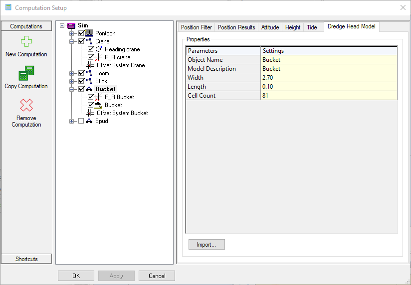
In the Profile Display the object drawing properties for deepest point and cut point of dredging tool become available.
Furthermore if the dredger type is a cutter dredger the dredge tool shape is plotted.
Benchmark
Template database setup
An object without attitude and heading sensors which would normally be at a fixed location. Normally used to monitor position stability.
The difference between the expected fixed location and the actual position as computed gives an indication about overall position accuracy.
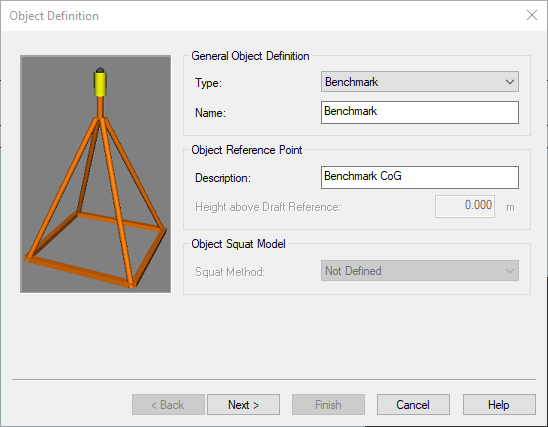
This object type should be used for objects which are used as benchmarks or target on structures. Objects of this type are not allowed to contain any systems. An example of this is:
-
USBL/LBL beacon located on the sea floor as a reference.
-
Beacons can also be on structures for surface range-bearing positioning like KM Radius or CyScan.
This is object is considered to be mostly a subsurface object (USBL/LBL beacons), but can also be surface range-bearing targets. Systems may not be added to the object.
It can not have its own Kalman & speed filter, as attitude & height priorities.
Gun Array
Template database setup
An object towed behind a vessel which is used to mount seismic air guns on.
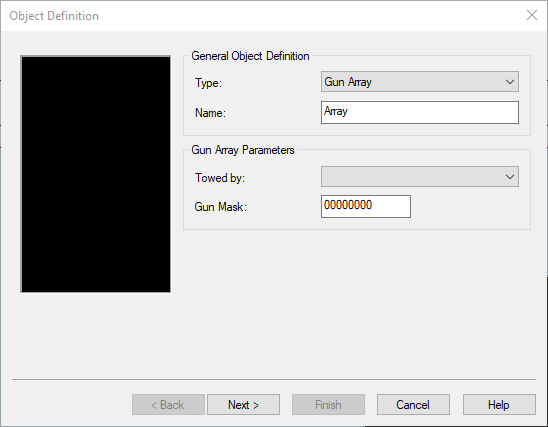
This object type should used for seismic gun arrays floating below the water surface. When this object type is used we allow the definition of the following items:
-
Gun mask and nominal firing pressure.
-
Offsets of tow points.
-
Individual gun locations and sizes.
-
Individual depth sensor locations, corrections & serial numbers.
-
Used units.
This is object is considered to be a subsurface object and systems can be added to the object.
It can have its own Kalman & speed filter, as attitude & height priorities.
How-to Geophysical Survey
More information about how to set up a Gun Array can be found:
Online
In the Computation Setup when selecting the Gun Array the following options become available:
-
Position filters: Under this tab filters can be selected to smooth the track of the positioning, using a Kalman Filter.
-
Position results: Under this tab the settings can be found for for setting how the object node positions are interpolated and predicted following the position updates or Kalman Filter updates at a triggering system update time.
When creating a generic export the gun array definitions can be used and a customize exportable node list becomes available.
Pipe Bundle
Template database setup
A flexible object in the form of a pipe which is towed behind a tug.
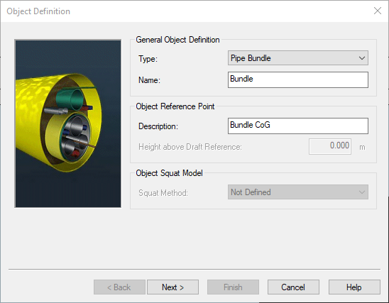
This object type should be used for non-rigid objects below the water surface. An example of this are towed pipe bundles which float beneath the water surface during their tow-out to the oil field.
This is object is considered to be a subsurface object and systems can be added to the object.
It can have its own Kalman & speed filter, but not attitude & height priorities.