DbSetup - Setup for Towed Streamer Seismic
On this page:
2D & 3D Towed Streamer Seismic
Template setup for a single source, single streamer seismic survey (2D) is quite straightforward, especially when there are no positioning type sensors attached to the towed streamer cable. Configuring a template database for a 3D survey with multiple guns, streamers and tailbuoys is a bit more complex, involving more sensors, e.g. compass and acoustic ranging systems.
Info
The information below only addresses those aspects of DbSetup that pertain directly to towed streamer seismic, including sub-bottom profiling when source and streamer are separate objects. Please refer to other Qinsy documentation for additional survey setup issues.
Geodetics
No different than the normal set up. Refer to the F1 inline Help 'Database Setup~Edit'.
Objects
Info
Only information pertinent to seismic objects is addressed here. Consult the F1 inline Help 'Database Setup~File~Object' for more general information about defining Objects.
The UKOOA/OGP P2 and P1 Data Exchange Formats provide helpful descriptions of object reference points and tow points. An extract is included below.
For a simple 2D survey at least three objects need defining; towing vessel, gun and streamer. A tailbuoy may or may not be used. Even if used it may not carry a positioning sensor.
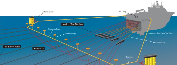
For a 3D survey there may be multiple guns and streamers as well as front floats and deflectors. The example has 2 gun arrays, 4 streamers and 4 tailbouys.
2D Seismic - Objects 3D Seismic - Objects
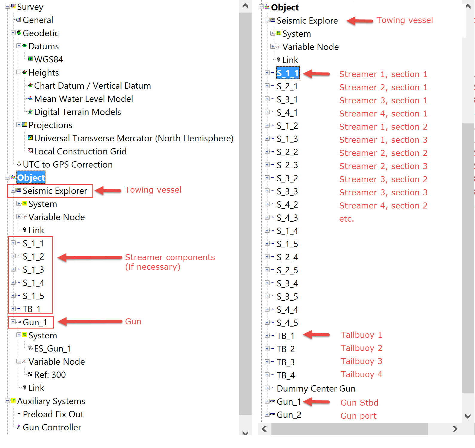
Object Definition - Towing Vessel
Does not differ from the usual Survey Vessel setup. Typically a variable node is defined for one or more tow points (e.g. for gun, for streamer). Refer to the online Help DbSetup File Object ObjectDefinition help for further details.
Object Definition - Gun Array
Gun Array Reference Nodes
A reference node for a gun array is automatically created and given the name "Ref:30x".
For the first gun defined "x=0" so the name is "Ref:300".
For the second gun defined "x=1" so the name is "Ref:301".
The third is "Ref:302" and so on.
These names are commonly used in the seismic industry but can be changed if desired.
A 2D survey uses one gun array while a 3D survey may use one, two or more gun arrays.
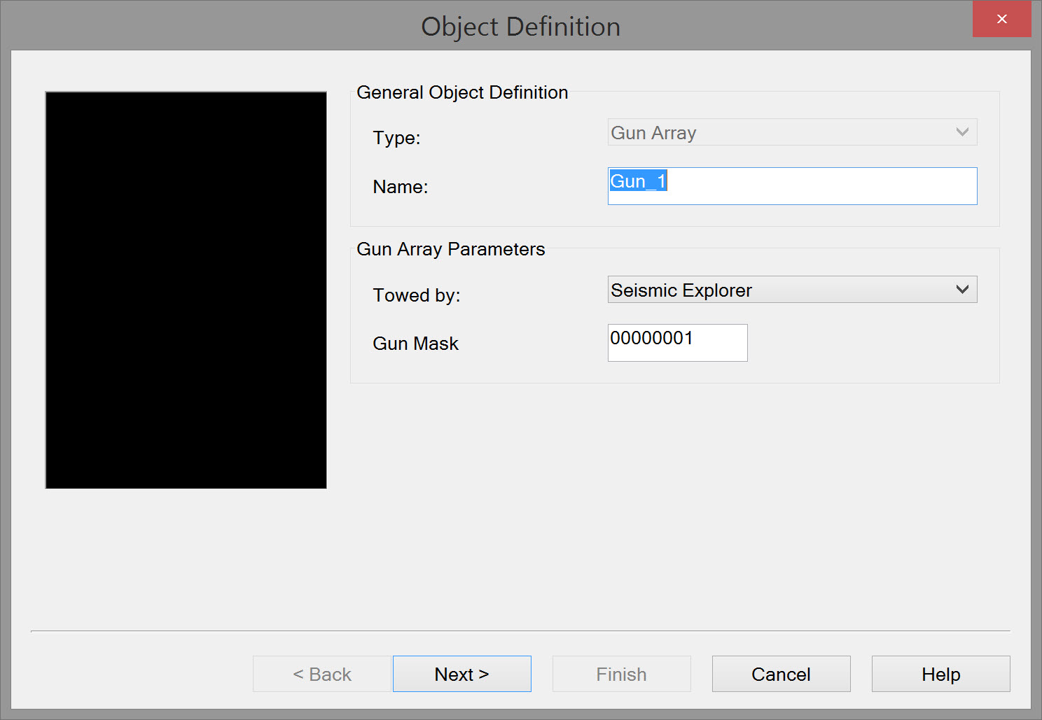
General Object Definition | |
|---|---|
| Type | Select 'Gun Array' from the drop down list. |
| Name | Enter a name. If multiple gun array objects are defined provide a unique name for each one e.g. Port Gun, Stbd Gun. |
| Towed by | Select the object/vessel towing the gun(s). In some operations guns are towed by one vessel and streamers by a second vessel. |
| Gun Mask | Some Gun Controllers require a 'gun array mask' to identify each gun array individually. Note: Using the mask properly requires adding a new Gun Controller System using a Gun Controller driver. |
Click Next.
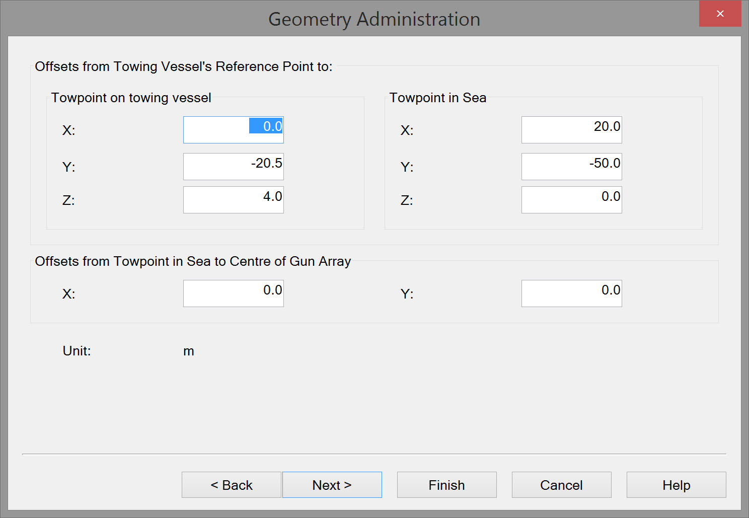
Geometry Administration | Values entered and recorded for administrative purposes and for export of data to UKOOA P2 and P1 formats. |
|---|---|
| Towpoint-on-towing-vessel | The offsets, defined in the project distance unit, from the vessel's reference point to the point on the vessel from which the gun array is towed. |
| Towpoint-in-sea | Gun arrays may not be towed directly from the towpoint-on-towing-vessel but from a towpoint-in-sea. The offsets, defined in the project distance unit, are from the vessel's reference point to the point in the sea from which the gun array is towed, e.g. a paravane. (A device which keeps a line with a towed object at a certain depth.) |
| Offsets from towpoint-in-sea to center of source | Enter the local offsets that reference the center of gun array (source) to the towpoint-in-sea. |
| Units | The defined project distance unit is displayed |
Click Next.
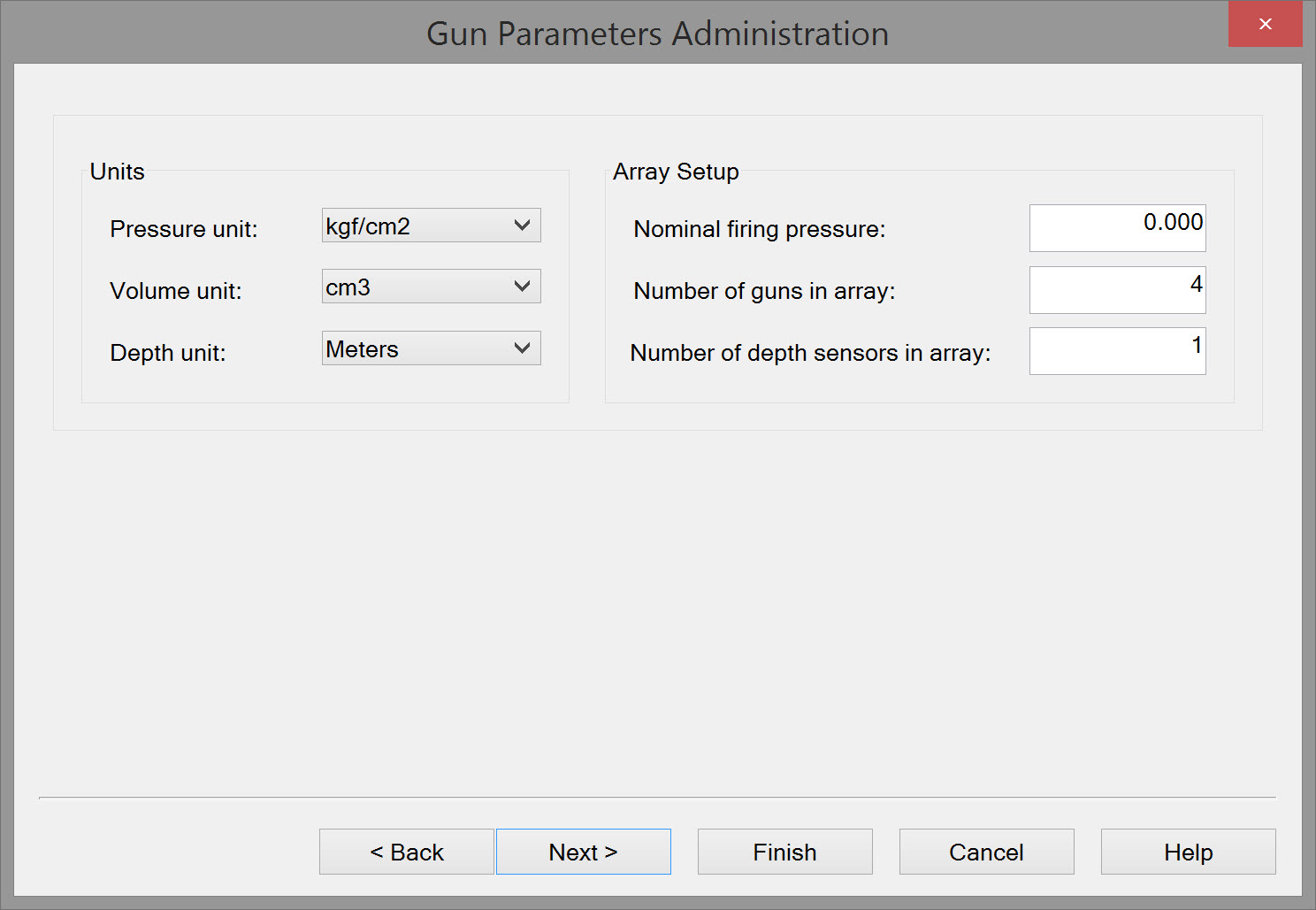
| Gun Parameters Administration | Values entered and recorded for administrative purposes; used in export of data to UKOOA P2 and P1 formats. |
|---|---|
| Units | Select the Pressure units used, Volume unit of the guns and the Depth unit. |
| Array setup | Enter the Nominal firing pressure which is the minimum pressure that has to be reached before the guns can fire; the number of Guns that make up the full gun array; and the number of Depth sensors which indicate the depth of the whole underwater gun array setup. An airgun array is commonly made up of several sub-arrays, or 'strings', which are suspended from floatation devices to maintain the specified operating depth. |
Click Next
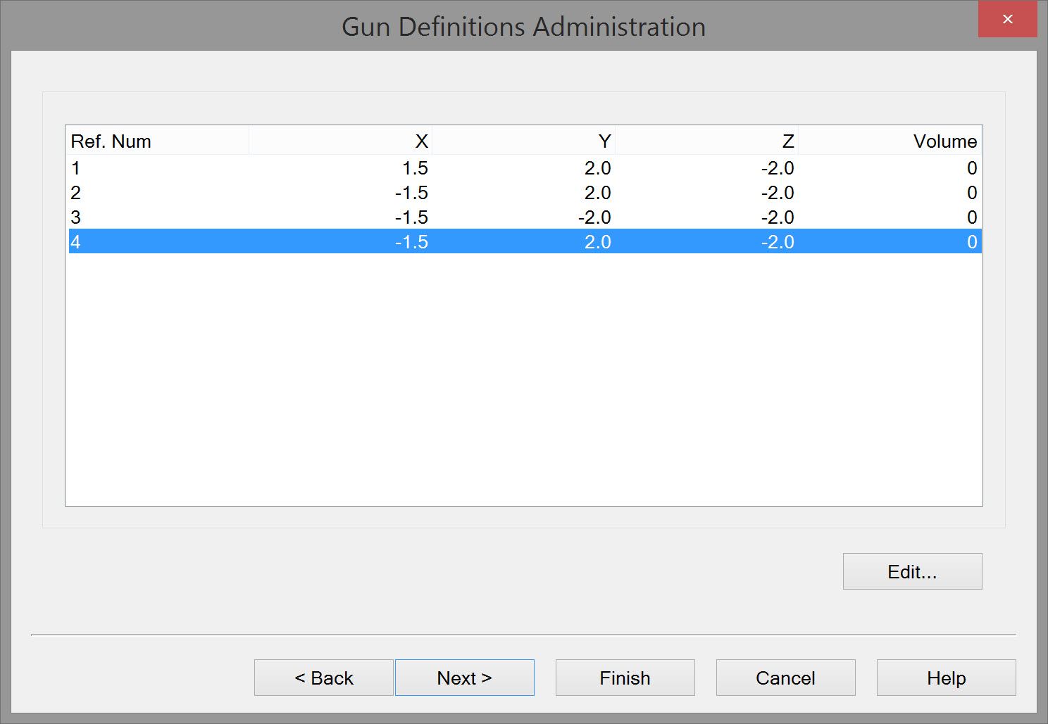
Gun Definitions | Values entered and recorded for administrative purposes; used in export of data to UKOOA P2 and P1 formats. |
|---|---|
| Gun Definitions Administration | The number of guns listed corresponds to the number entered on the previous page. Select each gun and press Edit, or double click to open the Edit Gun window. Enter the volume of the Gun. |
Click Next
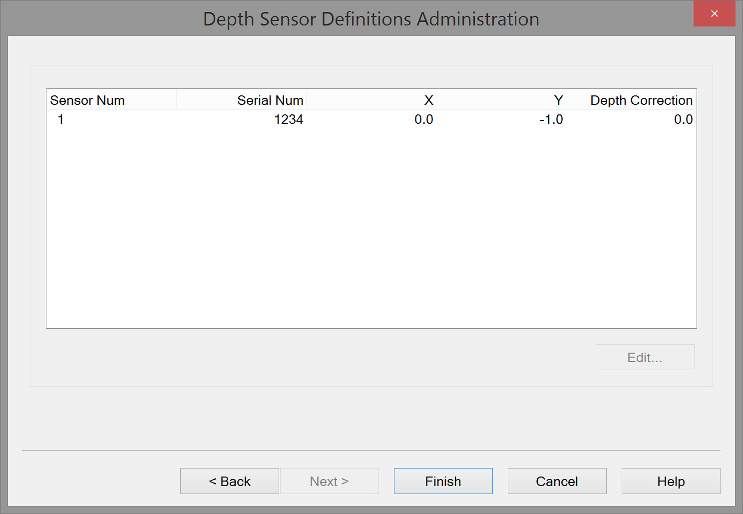
Depth Sensor Definitions | Values entered and recorded for administrative purposes; used in export of data to UKOOA P2 and P1 formats. |
|---|---|
Depth Sensor Definitions Administration | The number of Depth Sensors listed corresponds to the number entered on an earlier page. |
Click Finish
Below is an image of a typical setup with gun arrays and streamers behind a towing vessel:
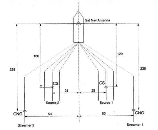
CNG - Center Near Group indicates the first receiver group on the Streamer.
CS - Center Source.
Return to top of page.
Object Definition - Seismic Streamer
Depending on the survey scenario a streamer may be defined:
- As a single entity, in which case it is normal to assume the streamer is straight and is towed directly behind the towing vessel, usually using vessel CMG to orient the streamer. This is the most likely scenario for 2D surveys with shorter streamers.
- With multiple segments in which case the second segment would be linked to the first, the third to the second and so on. This is the most likely scenario for a long 2D streamer incorporating positioning sensors and for 3D surveys. How many segments are defined is determined by the user but could be made dependent on the number of compasses arrayed along the entire streamer length. In the 3D example used here (for illustrative purposes only) there are five segments. Note: if there are no compasses or other positioning sensors on the cable, there is no sense in defining multiple segments (unless compass systems are defined with a Manual Driver, for user entered compass values).
Note
Parameter values shown in dialog box images illustrate principles and do not represent entirely realistic values.
Streamer object type is 'Towed fish' with the CoG located at the head of the segment, i.e. forward end.
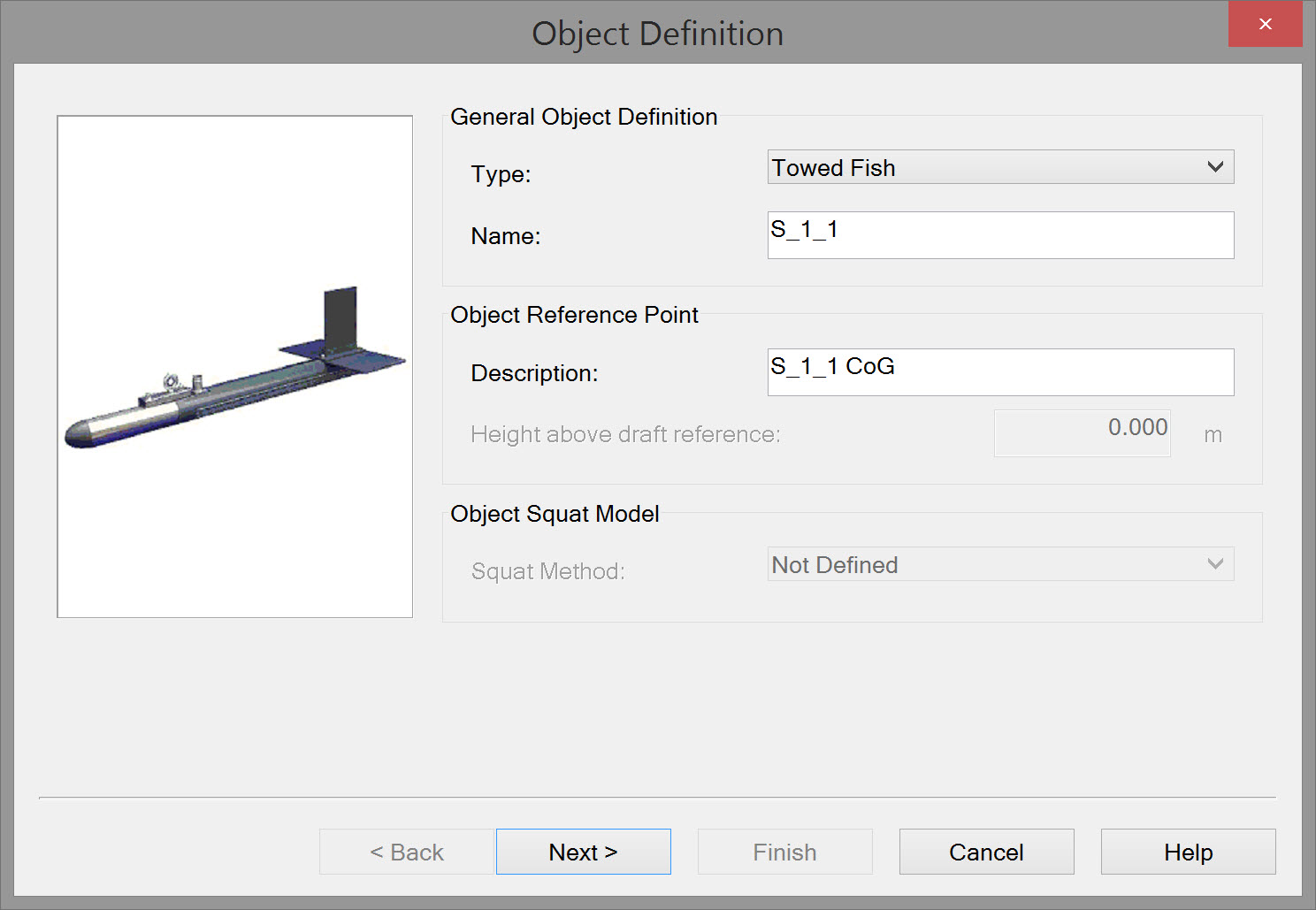
For visualization purposes during acquisition it is useful to define an object shape.
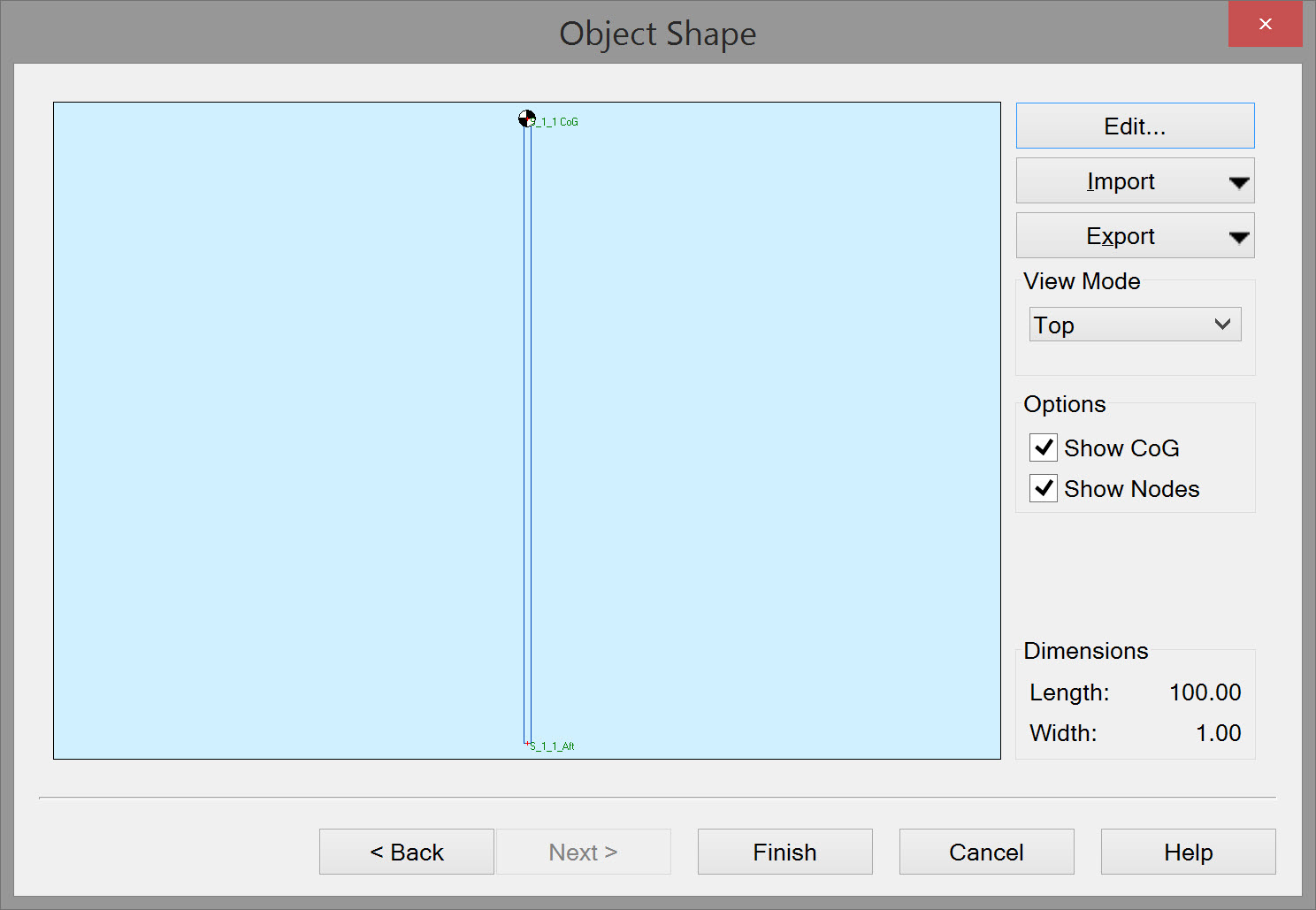
Add another Towed Fish object for each streamer section.
For each streamer section add a variable node at the aft end.
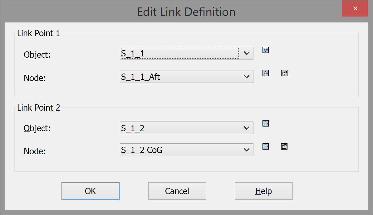
Streamer sections are linked one to the other using the 'Link' option listed in every Object tree. Double click on 'Link' to open the Edit Link Definition window.
| Edit Link Definition | |
|---|---|
| Link Point 1 | For Object select the most forward streamer section, and for Node select the variable node added to the aft end of this first section. If there is no predefined node add a new one using the Add  |
| Link Point 2 | The forward end of streamer section 2 must be linked with the aft end of section 1. For Object select the second streamer section, and for Node select the variable node at the forward end of the second section. If there is no predefined node add a new one using the Add |
Repeat the process to link all segments in a streamer.
Repeat the process for each streamer.
Object Definition - Tailbuoy
Defining a tailbuoy may or not be be necessary depending on the survey scenario. Where the streamer is assumed to be straight and follows the track of the towing vessel, there may be no tailbuoy, and, if there is, it may not have a positioning system mounted on it. In a 3D survey, each tailbuoy is usually equipped with a positioning sensor of some kind, e.g. rGPS.
Whenever a tailbouy object is need, it should be defined as a Towed fish.
Object Definition - Other
Definition of other objects may be required if they carry positioning sensors: front floats, diverters/deflectors/paravanes. These too would be defined as towed objects.
Applicable Systems
Info
Only information pertinent to seismic systems is addressed here. Consult online Help DbSetup~File~System for more general information about defining Systems.
Gun Controller
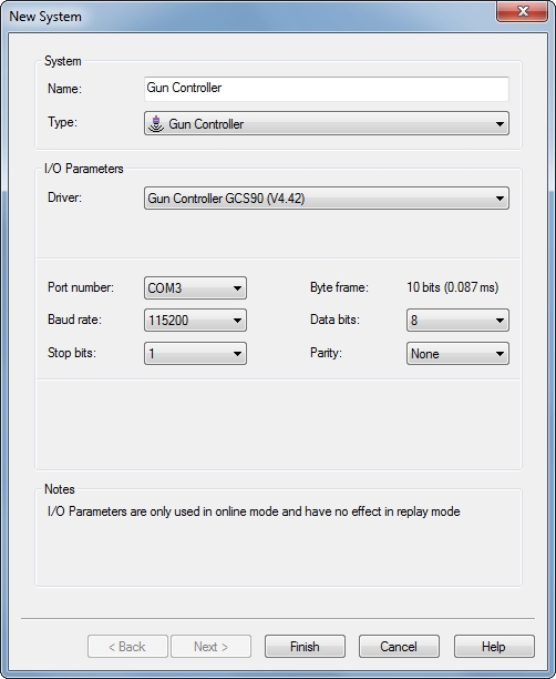
| New System | |
|---|---|
| Name | Enter a name easily recognized in displays Online. |
| Type | Select Gun Controller from drop down list. |
| Driver | Select driver. |
| Port Parameters | Enter the appropriate serial port parameter values. This port refers to the exchange of messages between QINSy and the Gun Controller. For example, outgoing messages from QINSy include items like line and next shot-point number; incoming messages from the Gun Controller include QC items such as which gun fired, pressure etc. |
Click Finish.
QPS Fix Device Mk3/4/5/6
The QPS Fix Device MK 6 is a hardware device manufactured by QPS for use with the Qinsy software. It is able to receive and/or send two closure (CLS) or TTL pulses.
Outgoing closures or TTL pulses can be used to trigger external devices, whereas incoming closures or TTL pulses can be used for PPS (Pulse-Per-Second) support and/or for fixmark triggering from other navigation systems.
Closures (CLS) or TTL pulses can be received or sent via BNC or DB9 connectors. Typically the PPS pulse is received on a BNC In connector. Serial data in and out uses the DB9 connectors.
Note
Please refer to QPS Fix Generator Boxes for a description of the particular Trigger Device model in use and the required cabling for different configurations.
NOTE: The Trigger Config Utility is located in the root directory of Qinsy and added to the Qinsy Console by right-clicking in the lower panel and selecting Add Program.
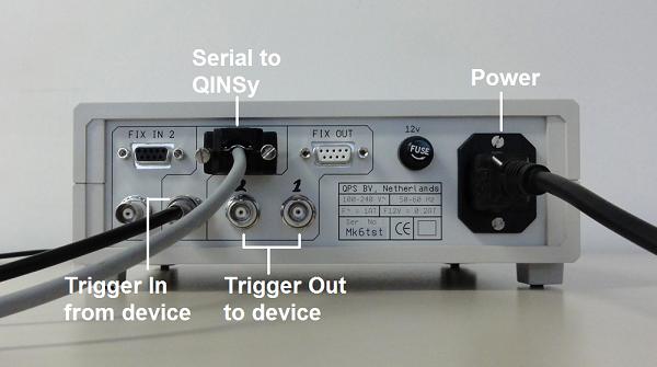
QPS Fix Device - Rear Panel with cables connected
For System Type choose 'Closure Output System'. Make sure you select the appropriate Driver (MK 6 in the example).
The Port number refers to the interface port to which the serial data cable is connected (Com2 in the example).
The cable runs between a comm port on the Qinsy PC to the Db9 labelled 'FIX OUT' on the Fix Device.
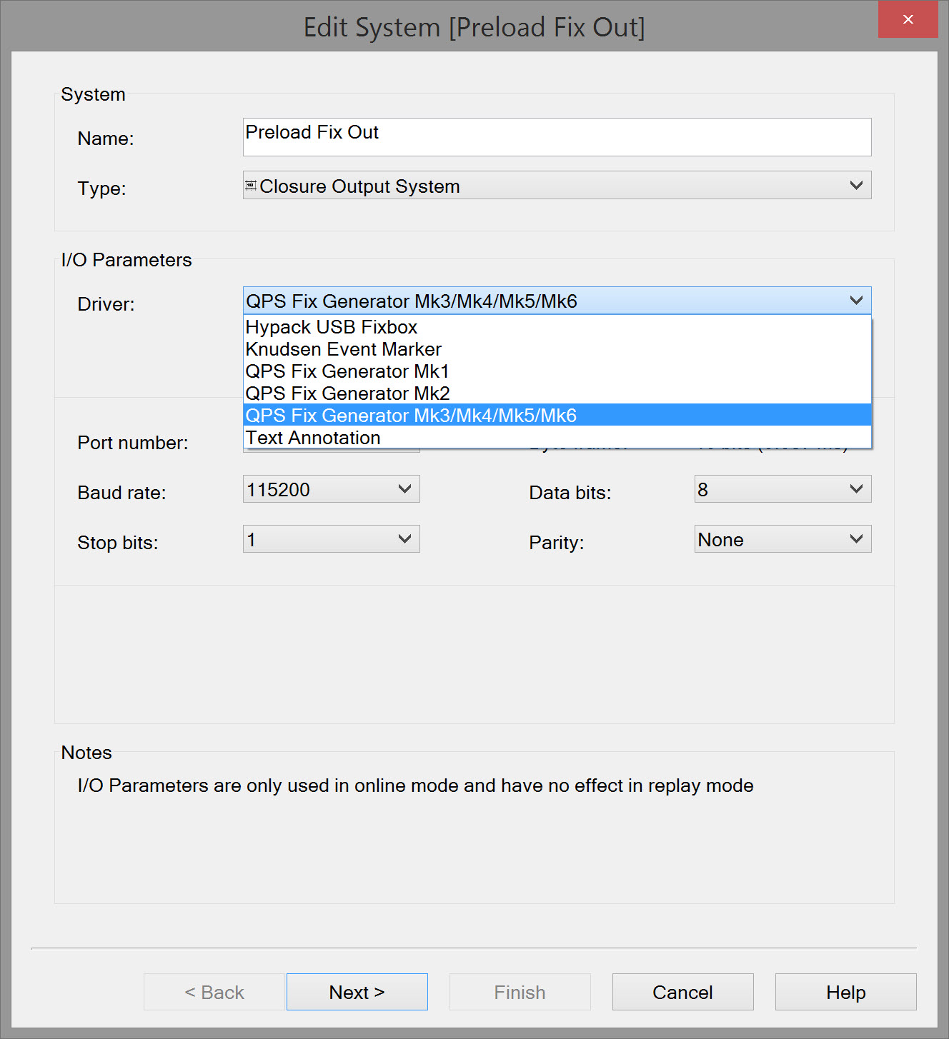
Click Next
Please Note:
The baud rate was changed since the MK 6. Make sure the correct baud rate is selected.
MK | Baudrate |
|---|---|
prior to the MK 6 | 19200 |
MK 6 | 115200 |
Select which of the 'Fix Out' BNC connectors is being used to send the Pre-load closure out to the Gun Controller. This is Port 1 in the example:
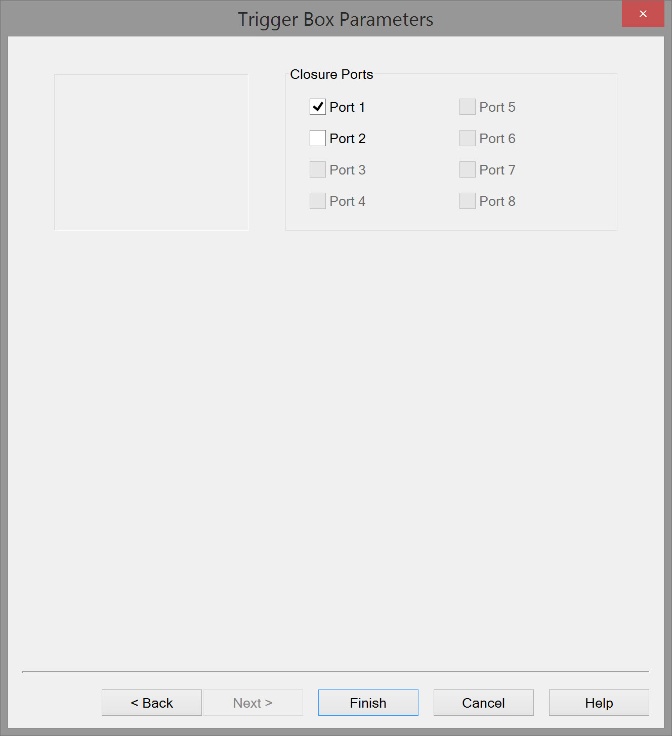
Click Finish
When combining a Qinsy 'Preload Fix Out' to a Gun Controller with a 'Trigger Fix In' from a Gun Controller the cable between the Qinsy PC and the trigger Device should be split so that it can be connected to two serial ports at the Trigger Device end.
The reason for the use of two serial ports on the Trigger Device is the fact that the 'Pre-load Fix Out' is generated by the driver 'DrvOutFix.exe' and the 'Trigger Fix In' signal from the Gun Controller is detected by the core process 'FixGenerator.exe'.
Both 'DrvOutFix.exe' and 'FixGenerator.exe' use the same COM port connected to Qinsy.
The following diagram details the necessary wiring.
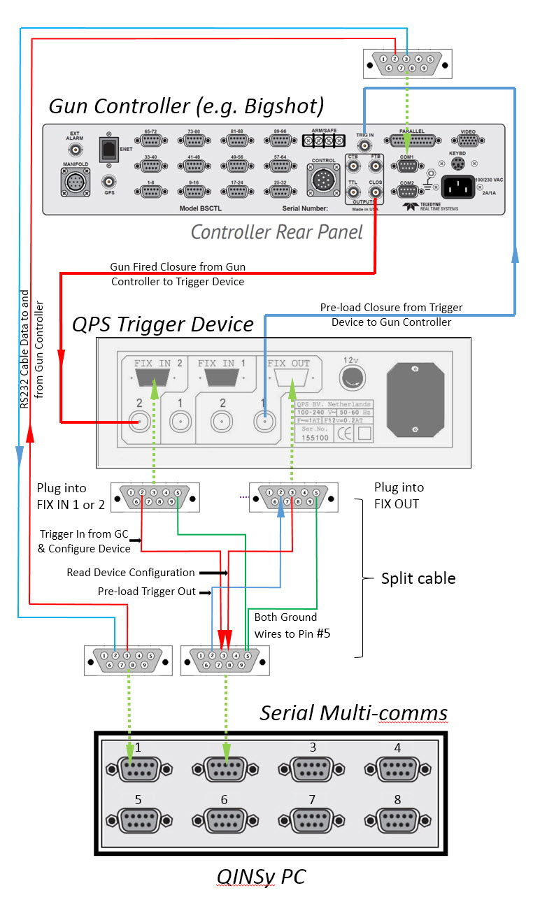
Both FixIn connectors behave exactly the same as the QPS PPS Device:
- BNC 5v pulse in, DB9 (Pin 2) RS232 pulse out (Fixed length). Output Voltage between -12 to +12V
- The Output signal is only a Fixed length pulse, not a character!
- Do not use that output signal to trigger a TTL system (0 to 5V), otherwise you will blow up that TTL input.
The FixOut Input on the DB9 (Pin 2) receives its Fixes (Out1, Out 2 or both) from the QINSy computer. The same Pin 2 is also used for the basic setting as CLS/TTL, Pos/Neg input (Trigger Config Utility).
- The outputs are CLS/TTL on the BNC connectors.
The FixOut Output on the DB9 (Pin 3) is only used to check the settings (Trigger Config Utility) e.g.
- FixIn or FixOut set to TTL or Closure
- FixIn set to Pos. or Neg. triggering
- Basic info like Serial Number, Date of Build, Microcontroller software versions, etc. No output pulses.
Trigger Config Utility
This utility is used to change the configuration of a QPS Trigger Device. If not found in the lower panel of the Console, right click there, select Add/Remove QPS Program and check the appropriate box.
The utility currently supports the following devices:
The utility automatically queries the user for the COM port to which the QPS Fix Device is connected. Once a COM port is selected the utility detects which specific QPS Trigger Device model is connected.
Since the QPS Fix Devices differ slightly it is possible the utility will display several settings as N/A. This depends on the type of QPS Fix Device connected.
The screenshot shown below displays the configuration of a QPS Trigger Device MK5.
As you can see the LED Controller version is indicated as N/A on this model whereas it is available with the MK6 model.
Configuring a QPS Trigger Device is as easy as selecting the correct configuration from the drop downs and clicking on the "Write" button. If Necessary the user can perform a read out of the configuration by clicking on the "Read" button.
Other Systems
The following table summarizes some of the other types of Systems that might be defined, depending on the survey spread:
Additional System Information
Please refer to the Drivers & Interfacing Manual and to F1 inline Help 'Database Setup~File~System' for more information on defining these systems.
'Dummy' Echosounder
It is strongly recommended to define a Single Beam Echosounder system with Manual Input Driver on ALL objects, even if the values entered remain as zero.
Objects would include towing vessel, gun arrays, front floats, diverters, tailbuoys, sub-bottom profiler fish, side scan fish, magnetometer.
Defining these 'dummy' echosounders provides much greater flexibility in exporting data, especially in user-defined formats.
| System Type | |
|---|---|
| Position Navigation | On towing vessel and potentially on gun arrays, front floats, diverters and tailbuoys. Some 3D Sub-bottom Profilers float on the surface and carry a position navigation system. PositionNavigationSystem |
| Gyro | On towing vessel. GyroCompass |
| MRU | On towing vessel. PitchRollHeaveSensor |
| Manual Layback (dX/dY/dZ) | In the absence of other positioning systems Laybacks may be used on the towing vessel to position gun arrays, front floats, diverters and tailbuoys. Also for towed sub-bottom profiler, side scan fish and magnetometer. DrvManualLayback |
| Cable Counter | On towing vessel if used to measure slang range to a towed object. Surface Navigation System |
| Echosounder | An echosounder may physically be installed and QINSy interfaced to it. In any case it is strongly recommended to define a Single Beam Echosounder system with Manual Input Driver on all objects, even if the value entered remains as zero. Defining such 'dummy' echosounders provides much greater flexibility in exporting data, especially in user-defined formats. |
| Surface Navigation Range & Bearing | On towing vessel to potentially position gun arrays, front floats, diverters, tailbuoys, and surface towed sub-bottom profiler. Such systems include rGPS and laser. Surface Navigation System |
| Side Scan Sonar | On towing vessel. SideScanSonar System |
| Magnetometer | On towing vessel. Magnetometer System |
| Compasses | On streamers. Gyro Compass |
| Depth Sensors | May be deployed on various objects including streamers, gun arrays, front floats, sub-bottom profiler fish, side scan fish. Underwater Sensor |
| Acoustic Ranging | Potentially mounted on towing vessel, gun arrays, front floats, diverters, streamers and tailbuoys to measure a network of ranges between various nodes on these objects. Underwater Sensor |
| Acoustic USBL | On towing vessel to position objects such as towed sub-bottom profiler, magnetometer, and side scan fish. USBLSystem |
| Time Synchronization | On towing vessel. Time Synchronization System |
| Output - various | From Qinsy to third party systems and to file, e.g. autopilot, Generic ASCII Data Logger, Generic Output (User-defined ASCII), NMEA, sub-bottom profiler, side scan, seismic systems, Syntrak 480, video overlay etc.. Both serial and network drivers are available. Output Systems |
Return to top of page
UKOOA Definitions
Reference points
Each ship has its own co-ordinate frame, with its origin defined as the ship's reference point.
All towed objects, such as streamers, gun arrays and buoys, have their own local reference point and points on these objects are described in terms of local offsets relative to the local reference point.
Tow points
The header records of the P2/94 format describe the nominal, or design geometry of the spread, in which all towed objects are towed parallel to the longitudinal axis of the towing vessel, the Y-axis of its co-ordinate frame. Each towed object 'streams' from a towpoint, which may be offset from the vessel by means of a paravane. This towpoint is defined in P2/94 as the 'towpoint-in-sea', as opposed to the point on the vessel the towed object is attached to, which is called the 'towpoint-on-towing-body'.
This distinction is only relevant in the case where a paravane is used to offset the towed object from the vessel. When the object is towed directly from the vessel or from a boom rigidly attached to the vessel, the 'towpoint-in-sea' and the 'towpoint-on-towing-body' are coincident.
Some towed objects are in turn towing another towed object. Examples are a tailbuoy towed by a streamer and a front buoy towed by a gun array. Assuming that the buoy is towed straight behind the streamer or gun array the towpoint-in-sea coincides with the towpoint-on-towing-body, which is the point on the streamer or gun array the buoy is being towed from. Note that the 'towing vessel' in this case is not the ship, but the streamer or gun array.
Local offsets and reference points
Each towed object has its own local co-ordinate frame of which the axes are parallel to the ship's X, Y and Z axes (that is: in the design, or nominal, geometry). However, the local offsets on each towed object are measured from its local reference point. For all towed objects except the streamers the local reference point is the towpoint-in-sea, defined for that object. The towpoint-in-sea may of course coincide with the towpoint-on-towing-body, as explained above. The only exception to this rule is the local reference point of a streamer, which is defined as the centre of the near receiver group of that streamer, the receiver group closest to the towpoint. Note that therefore Y-offsets along a streamer are negative and decreasing towards the tailbuoy behind the centre of the near receiver group.
Offset mode: polar or rectangular
Horizontal offsets may be given either as polar or rectangular co-ordinates. The offset mode must be consistent for all offsets defined.
Polar mode:
Offset A = radial distance from ship's or local reference point to the point defined;
Offset B = angle, measured in the ship's or local reference point, clockwise from ship's head to the point defined.
Rectangular mode:
Offset A = X axis offset from ship's or local reference point to the point defined, measured positive to starboard.
Offset B = Y axis offset from ship's or local reference point to the defined point, measured positive towards the bows. (See Figure 3 for clarification.)
Z-axis offset or height
The third offset co-ordinate, along the Z-axis, is always positive upwards. Depths (of e.g. acoustic transducers) are therefore recorded as negative heights, with the minus sign included in the fields
provided.
Units of measurement
Offset distances may be expressed in metres decimal or international feet.
Offset angles may be expressed in degrees decimal or in grads.
The same measurement units must be used consistently for all offsets defined.
NOTE:
The offsets to the towpoints in columns 11 to 56 are measured relative to the ship's reference point.
The local offsets in columns 58 to 71 are measured relative to the local reference point: the centre of the near seismic receiver group.
The towpoint-in-sea is expected to be defined at sea level. The local Z-offset is measured vertically from the local reference point (the near receiver group) to the towpoint-in-sea.
As the towpoint-in-sea, when defined at sea level, is higher then the local reference point, its local Z-offset is a positive figure and equals the nominal depth of the streamer.
Return to: top of page
Return to: 2D and 3D Towed Streamer Seismic Surveys

