Controller - Setup for Towed Streamer Seismic
On this page:
Controller - 2D & 3D Towed Streamer Seismic
The main issue for seismic surveys, and to some extent geophysical surveys, is the set up of 'fixing' of shot-points.
When interfaced to a GCS90 compatible gun controller, it is useful to open the Gun QC Display.
Info
The information below only addresses those aspects of Online Data Acquisition that pertain directly to towed streamer seismic, including sub-bottom profiling when source and streamer are separate objects. Please refer to other QINSy documentation for additional data acquisition issues.
Computation Settings
In general, settings are similar to any other type of survey as described in F1 inline Help 'Controller~Settings~ComputationSetup'.
Of course it is important to check that all the appropriate objects and systems are enabled, including the 'dummy' echosounders defined for each object in the spread (see DbSetup - Setup for Towed Streamer Seismic -Other Systems).
Pay attention to:
Manual Layback Settings
If one or more #Manual Layback (dX dY dZ) systems are being used, pay particular attention to the 'Use Z' parameter, especially when an 'ROV Depth' observation has been defined for the layback object.
Generally use one or the other. Otherwise height conflict messages will pop up.
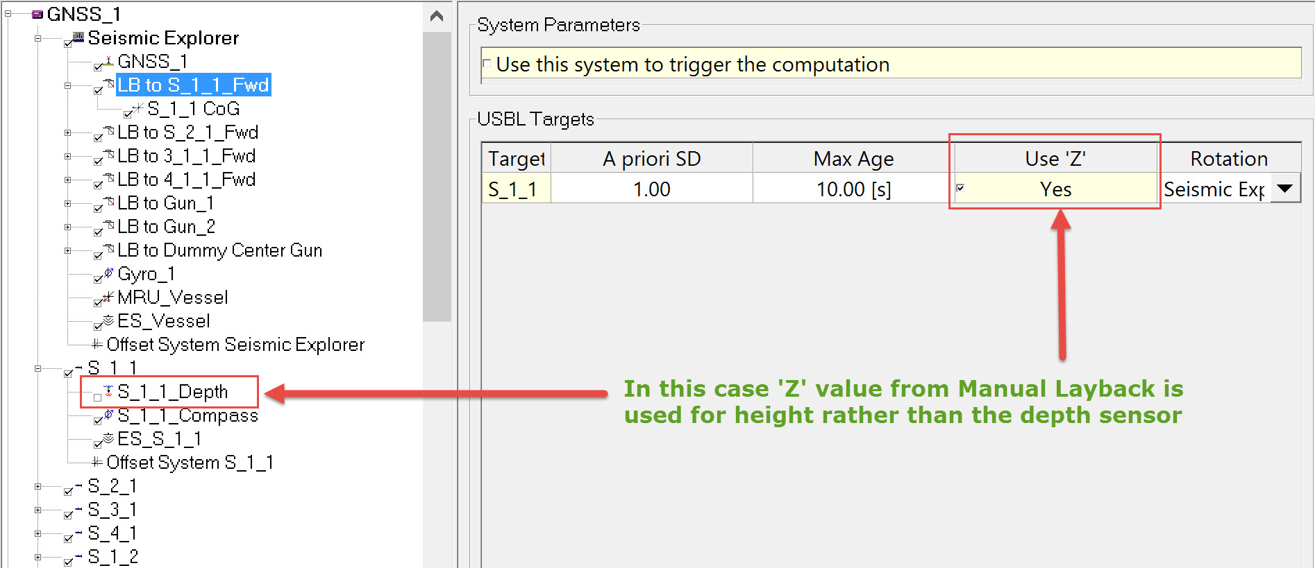
If 'Use Z' is enabled, the dZ value from the layback will determine the height of the towed object. If 'Use Z' is disabled, the computation uses the ROV Depth observation instead.
Depths at Streamer Links
Assuming depth sensors have been defined for the forward and aft ends of each streamer section, be aware that at link points, only one depth sensor can be enabled.
For example, if the depth sensor at the aft end of streamer Section 1 has been enabled, the depth sensor at the forward end of Section 2 must be disabled. Otherwise the link will not work because it has two depths associated with it.
Steered Node
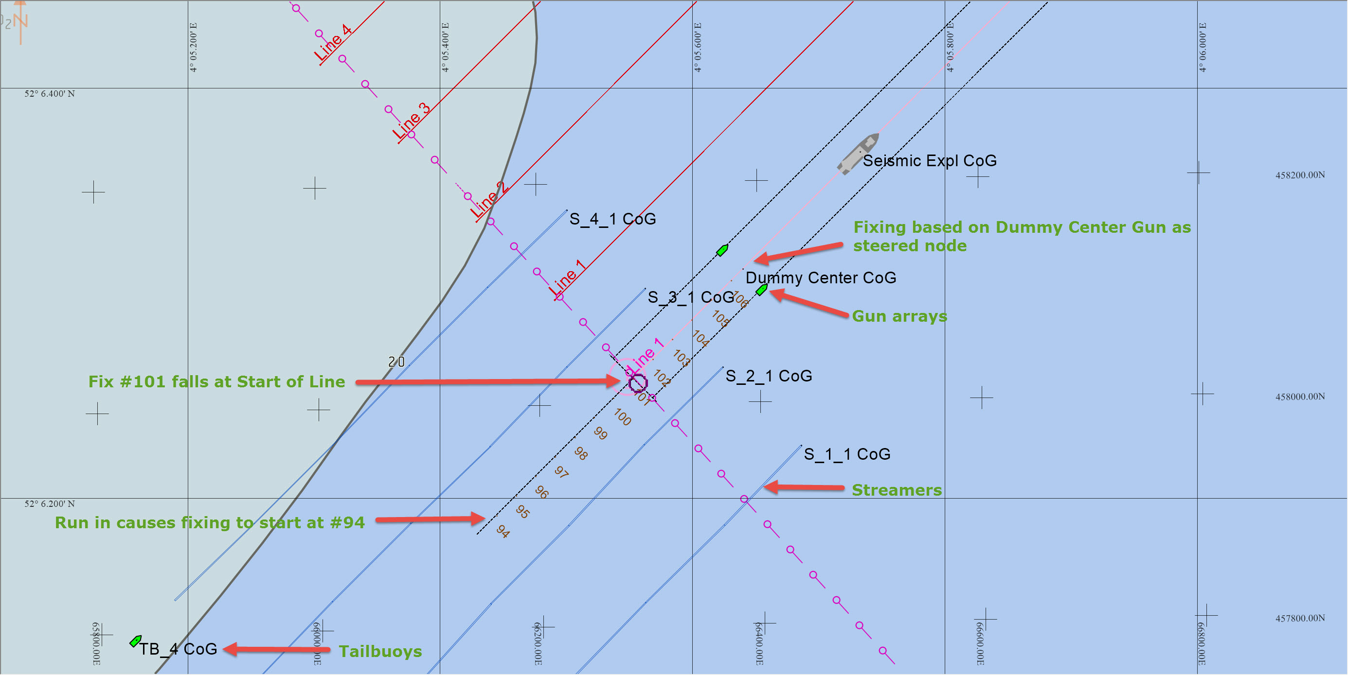
According to the UKOOA P2/94 format description the 'Start Of Line' is defined as the planned position of the vessel reference point at the first shot of the line. However it is the position of 'center of guns' at each predefined shot-point that is needed. Referencing the image below, it is clear that by designating the vessel CoG as steered node fix #101 would have been generated at the Start of Line as the CoG reached the first shot-point location. But the center source (gun) would still be some distance from that shot-point location, i.e. around fix #94. Defining the center source as the Steered Node enables generation of Fix #101 at the first shot-point location at which time the vessel CoG is some way further down the line.
Note that in this example with two active guns, a third 'dummy gun' has been defined as a Towed Fish object (not as a gun array) and designated as the Steered Node both for offtrack vessel steering and as an along line reference for shot-point distance calculations.
In the end it is the client or the seismic contractor who decides how they want fixing. QINSy is flexible enough to accommodate most situations.
Session Setup
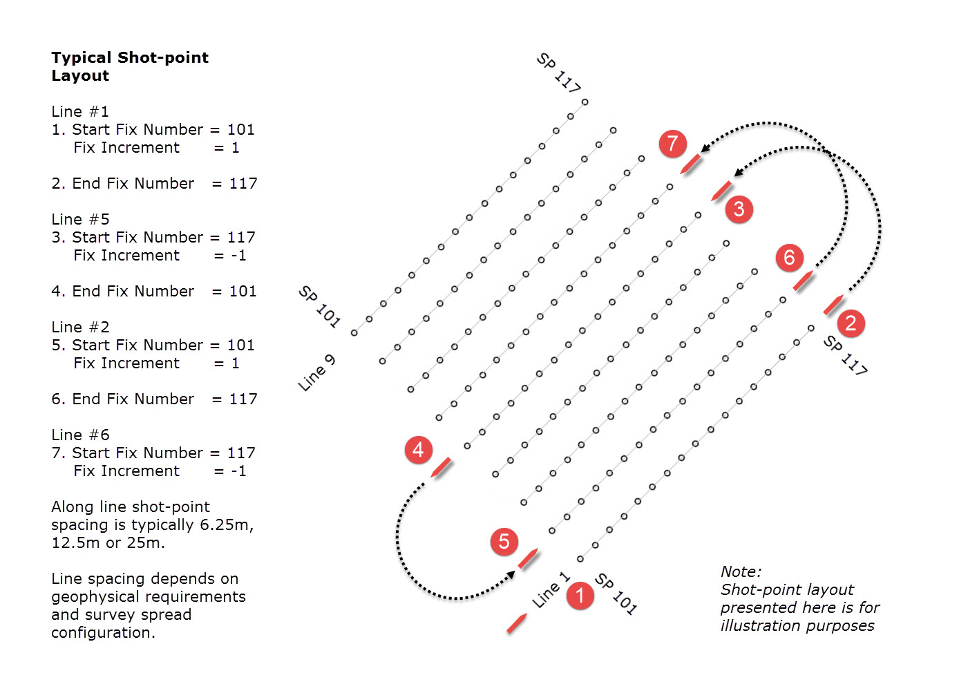
Positioning data is usually acquired by sailing multiple parallel straight lines. 'Shot-points' are arrayed at set intervals along each line; typically shot point spacing is 6.25m, 12.5m or 25m (or the equivalent in feet).
The objective is to fire the sound source at the exact moment it reaches each shot-point, at which time a position fix is taken. In most cases the requirement is to use the same shot-point number (SP#) at the start of each line. If lines are all the same length, the last SP# should be the same on each line.
The shot-point increment is -1 when shooting a line in the opposite direction.
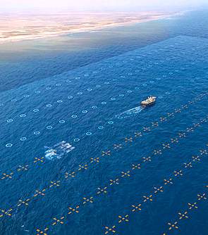
The picture and diagram below illustrate the principle:
Fixing (Eventing)
Shot-point Interval
In seismic, the distance traveled is based upon inline distance along the sailed line, in survey units. The actual sailed distance may be slightly longer due to deviations offline by the vessel.
In order to achieve the objective, fixing needs to be configured correctly. Settings are slightly different when interfaced to a gun controller and when not interfaced.
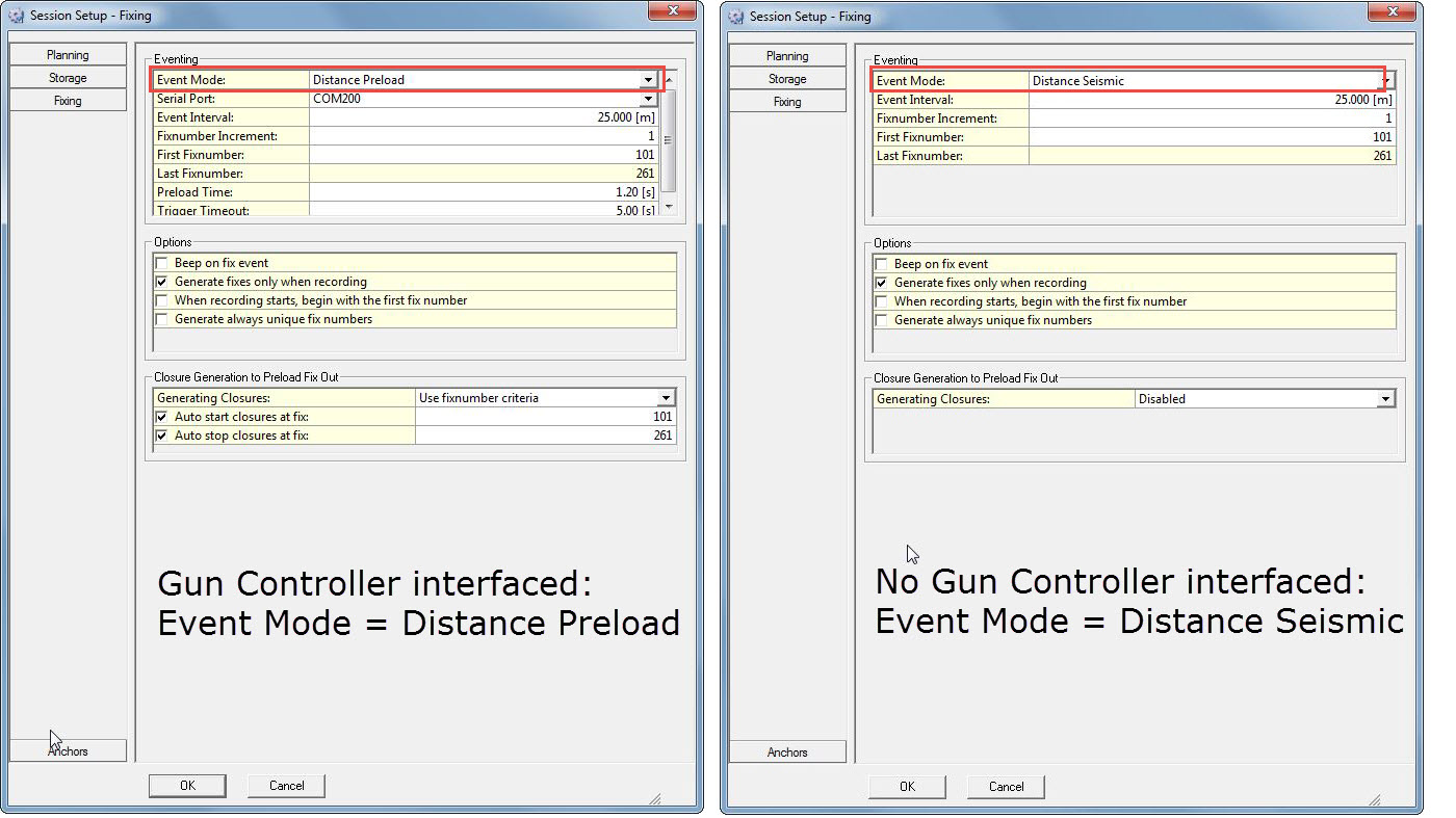
| Eventing | |
|---|---|
| Event Mode | Gun Controller Interfaced, select Distance Preload - For each shot-point, a FixOut signal to a Gun Controller is generated a little before the steered node (usually center of source node) reaches the nominal fix position (i.e. planned location of the next shot-point). The spacing between shot-points corresponds to the Event Interval entered. Vessel course and speed are used together with the Event Interval to predict time of arrival at the next shot-point. For this exchange of fix signals to happen a Fix Output System (e.g. QPS Trigger Device) must be defined in Database Setup. No Gun Controller interface, select Distance Seismic - the behavior of this option is similar in terms of calculating when to take a fix, but does not factor in a preload time interval. |
| Serial Port | Only available when Event Mode is set to 'Distance Preload' or 'Trigger'. Refers to the QINSy PC comm port on which the FixIn trigger is received from a peripheral device, e.g. Gun Controller. |
| Event Interval | Enter the nominal distance between shot-points in survey units. Usually this is 6.25m, 12.5m or 25m (translate to feet if necessary). Based on course and speed, actual fixes at shot-points will be taken as close as possible to the Event Interval. |
| Fixnumber Increment | Typically this is '1' in seismic but can be anything. |
| First Fixnumber | Any number may be entered. Typically Fix 101 is used in seismic. Note: See explanation in Options/'When recording starts, begin with the first fix number' below. |
| Last Fixnumber | This number is calculated based on the First Fixnumber and the length of survey line. Note: See explanation in Options/'When recording starts, begin with the first fix number' below. |
| Preload Time | Only available when Event Mode is set to 'Distance Preload'. This equates to the ramp up time needed for the gun(s) to charge ready for firing. |
| Trigger Timeout | Only available when Event Mode is set to 'Distance Preload'. The gun controller sends back a trigger FixIn to indicate when the gun(s) are fired. |
| Options | |
|---|---|
| Beep on fix event | If this box is checked, a beep is heard from the computer speaker at each fix, no matter how the fix is generated. |
| Generate fixes only when recording | Enable this option when you only want to create fixes when recording, which is usually the case in seismic and geophysical work. |
| When recording starts, begin with the first fix number | Enable this option when you want the fix number to be reset to the first fix number when recording is started, which is usually the case in seismic and geophysical work. |
| Generate always unique fix numbers | Enable this option when you want the last fix number to be remembered, even when you close the Controller. |
| Reset unique fix number to first fix at the next event | This option is only available when the "Generate always unique fix numbers" option is enabled. The fix number is reset to the value you enter as "First Fixnumber" in the Eventing section of the dialog. This option normally only happens once per project as it is used to create unique fix numbers for the whole project. |
| Closure Generation to Preload Fix Out | |
|---|---|
| Generating Closures | This option refers to the generation of a preload Fixout signal going to a QPS Fixr Box where it is converted to either a closure (CLS) or TTL pulse for transmission to the Gun Controller. There are three choices: Disabled - No Fixout signals are generated. Always active - Fixout signals for output are generated all the time as long as fixes are being updated internally in Qinsy irrespective of other settings. Use fixnumber criteria - Fixout signals for output are generated based on settings under Eventing and Options. For example if |
| Auto start closures at fix | Enter the fix number at which closure output should begin. |
| Auto stop closures at fix | Enter the fix number at which closure output should end. |
Activate Fixing
Please realize that Fixing will be active as soon as you press OK (you will see the value in the Controller window incrementing/decrementing).
If you have selected Time, Distance Sailed or Distance Along as the fixing mode, then fixing will begin immediately (assuming you are moving).
If you selected Manual then manual fixes (F9 hotkey) can be taken.
Distance Preload and Distance Seismic are dependent upon the steered node being between the start and end of line co-ordinates.
Difference between Distance Seismic and Distance Along
When using Distance Seismic each fix number is positioned relative to the start of the line in such a way that fix numbers will always be at the same position along the line.
The first fix generated will therefore be different from the specified first fix number (unless you start fixing very close to the SOL).
When using Distance Along, however, the first fix number you ask for is the first fix you get - regardless of position relative to the SOL.
In both cases the fixes are always in the same place along the line.
When using Distance Seismic, the direction of the fix numbering is determined by the planned line direction only, rather than the line bearing during acquisition.
Distance Seismic can work in both directions if used with a negative fix increment when starting from the end of the planned line.
Data Storage - Control
Info
The following descriptions do not include all available options because some have limited, if any, value in seismic surveys.
Please refer to F1 inline Help 'Controller~Settings~SessionSetup~Storage' for more information.
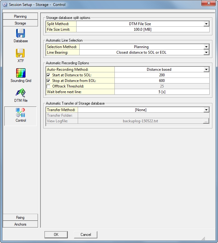
| Automatic Line Selection | |
|---|---|
| Selection Method | Use Planning - In seismic lines are normally sailed very much to plan, primarily to minimize long turnaround times due to the length of towed objects.
|
| Line Bearing | 'Heading based' or 'Closest distance to to SOL or EOL' are the best choices for seismic.
|
| Automatic Recording Options | |
|---|---|
| Auto-Recording Method | Use 'Distance based' for seismic. |
| Start at Fix | Enter the fix number at which to start recording - often #101. Fix numbers are often predefined during seismic operations and can be obtained from the client. |
| Stop at Fix | When using Event Mode 'Distance Preload' or Distance Seismic, the last fix number is computed based on length of line and shot-point interval. |
| Offtrack Threshold | Enter the Offtrack limit beyond which recording is paused. One value serves both port and starboard. Option appears after enabling the 'Start at' line. |
| Wait before next line | Enter how long the software should wait before selecting the next line. Not really applicable to seismic. This gives the helmsman time to steer the vessel off the current line, or to disconnect the autopilot. Option appears after enabling the 'Stop at' line. |
| Start at Distance to SOL | Enter how far before the Start of Line recording should take place. Leave the value at zero when you want recording to start at the beginning of the line. Enter a positive value to start recording before the start of line. Enter a negative value to start recording after the start of line. Typically a run-in to the SOL is used in seismic in order to straighten up and align all the towed objects with the line bearing. |
| Stop at Distance from EOL | Enter how far after the End of Line recording should take place. Leave the value at zero when you want recording to stop at the end of the line. Enter a positive value to stop after the end of line. Enter a negative value to stop before the end of line. Typically a run-out is used in seismic in order to clear all the towed objects past the EOL. |
| Start at MP | Enter at which distance along the main line recording should start. |
| Stop at MP | Enter at which distance along the main line recording should stop. |
Data Storage - DTM File
DTM data is motion and heading corrected geo-referenced footprint data from an echosounder (multibeam, multi-transducer or singlebeam) or laser scanner system. Transducer positions are also stored.
The DTM data can be stored in several formats, ready to import into QPS processing software (Validator, Fledermaus, Qimera), or other third party programs (Terramodel, CARIS, Cyclone, etc.).
In seismic it is usual to export data in UKOOA/OGP formats: P2/94 for raw data and P1/90 for post plot data. In current versions of QINSy (May 2015) neither of these exports relies on storing a DTM file. Exported data is drawn from *.DB and *.RES files.
Note that changes are planned in the near future.
However, even in current versions, and as recommended elsewhere, it is highly desirable to define single beam echosounders (ES) on each of the objects in DbSetup, and to then record DTM files during data acquisition, even if the recorded ES values are meaningless.
The fact that an ES is associated with an object means that transducer positioning data can be stored in *.QPD files, which offers much greater flexibility in exporting data in cases where P2/94 and P1/90 do not meet all the client's requirements.
Info
The following descriptions do not include all available options because some have limited, if any, value in seismic surveys.
Please refer to F1 inline Help 'Controller~Settings~SessionSetup~Storage~DTMFile' for more information.
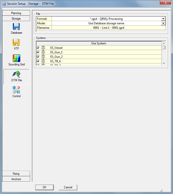
| File | |
|---|---|
| Format | *.qpd - QINSy Processing - is the recommended format. It is a proprietary format which can be imported into the Validator, Qimera or Fledermaus for further processing, analyzing and/or publishing. It is possible that one of the '*.pts - ASCII' formats is useful. |
| Mode | The mode determines the name of the storage file: Use Database storage name - By Default and Recommended. The DTM file will have the same storage name as the raw data file. This is highly recommended, since some processing tools require a DTM file to have the same name as the corresponding database. User-defined name - User is able to enter a different file name. This is not recommended. |
| Filename | A preview of how the file name will look. |
| Systems | |
| Use System | Activate the echosounder system(s) that should be used for the generation of the DTM file. |
| Layer name | This setting is only available when File Format is set to '*.pro - QINSy Mapping'. |
Displays
It is assumed the reader is familiar with most QINSy displays. If not refer to F1 inline Help 'DisplayManager~AddDisplay' for a list of all the options.
Each display has a separate detailed description.
GunQC
The Gun QC Display, only available when interfaced to a Gun Controller System, provides useful information about the gun(s) status and performance.
The Gun QC Display menu can be reached through: Controller - Options - Displays - Add Display, if a Gun Controller System was added to Database Setup.
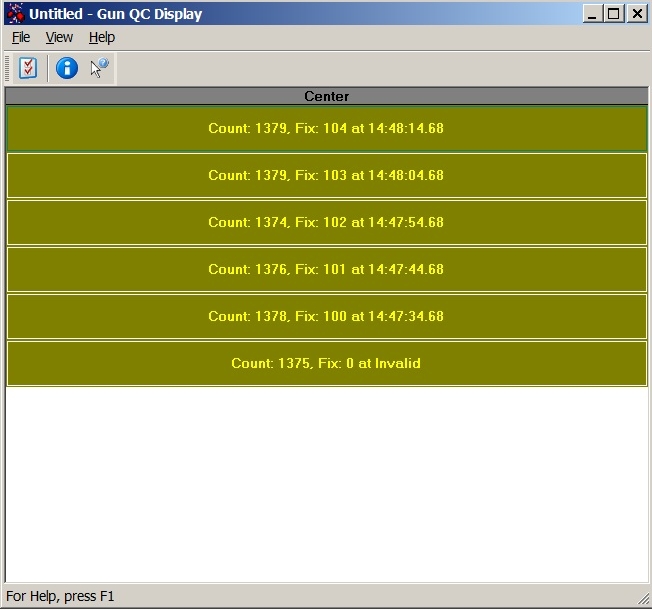
| Gun QC Display | |
|---|---|
View | Set the general viewing options for the display. |
Help | View the Help documentation about the Gun QC Display. Or use 'About' to check on the version of this executable. |
File | Close the display. |
View
The View menu contains the following options:
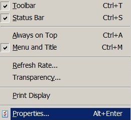
| View | |
|---|---|
Toolbar | Toggle tool bar on/off. |
Status Bar | Show the status bar at the bottom of the page. |
Always on Top | Show this display first when overlaying other displays. |
Menu and Title | Turn on/off menu bar and title of display. Double click with the left mouse button to reappear. |
Refresh Rate | Adjust the refresh rate of the display. Enter value in Hertz. |
Transparency | Normal Window - Regular window appearance. |
Print Display | Hardcopy print is made to the default printer. |
Properties | Open the View Properties window to set which items should be shown in the Gun QC Display. |
Properties
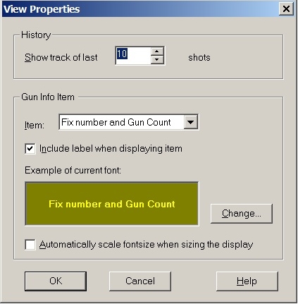
| History | |
|---|---|
<Change> | Change the font, text size or color of the text in the display. |
Automatically scale font size when sizing the display | When activated the text will be adjusted when the display changes size. |
Gun Info Item | |
Include label when displaying item | The selected label in Item will also be displayed in the window. |
Item | Choose which items to show in the display. For a list of items, see below. |
Show track of last x shots | Enter the number of shots to be shown in the screen. |
| Item | |
|---|---|
Fix number and Gun Count | QINSy Fix number and Counter number from Gun. |
I/O Time header | Time of arrival of the string from the gun. |
Gun Counter | Counter number from Gun. |
Array Mask | Defined Gun Mask in setup. |
Trigger Mode | Internal or External. |
Gun Time | Time of firing the gun array(s). |
Sequence | Sequence number. |
Total Subarrays | Number of gun strings (sub-arrays) in an array. |
Total Guns | Number of guns in an array. |
Total Active Guns | Number of active guns in an array. |
Total Delta Errors | Number of inoperative guns (guns that did not fire). |
Total Auto Fires | Number of fires. |
Total Miss Fires | Number of miss fires. |
Delta Spread | Total error spread for shot, in 1/10th ms. |
Total Volume | Volume of airgun. |
Manifold Pressure | Pressure of airgun. |
Deep Tow | Yes or No. |
Return to: top of page
Return to: 2D and 3D Towed Streamer Seismic Surveys
