Exporting Seismic - All Data Generic
On this page:
All Data Generic Wizard
Info
Please refer to the Generic Layout Editor for complete details of this export routine. Only a limited description is presented here as it relates directly to seismic data export.
Both raw and results data can be selected for export to an ASCII text file. Most of the seismic output comes from 'Result Data'.
Items and their layout are saved to an Export Layout XML file which is stored in subfolder \XML\Export of the current Project's Settings folder, or in the current \Support Settings folder.
Due to the extreme flexibility of this program it is possible to format an output somewhat akin to the official UKOOA P1/90 format if that is the objective. Otherwise a format that is readable by a third party application can be specified.
Note
The Generic Layout Editor is used by component ExportGeneric.exe
A recorded raw database (*.DB) file must be available, and additionally a results (*.RES) file, in case RESULTS DATA items are part of the selected layout.
In the Raw Data Manager highlight the files for export and select 'Actions - Export', or click on the icon:

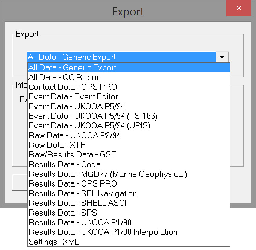
Select 'All Data Generic' and click OK to open the export wizard:
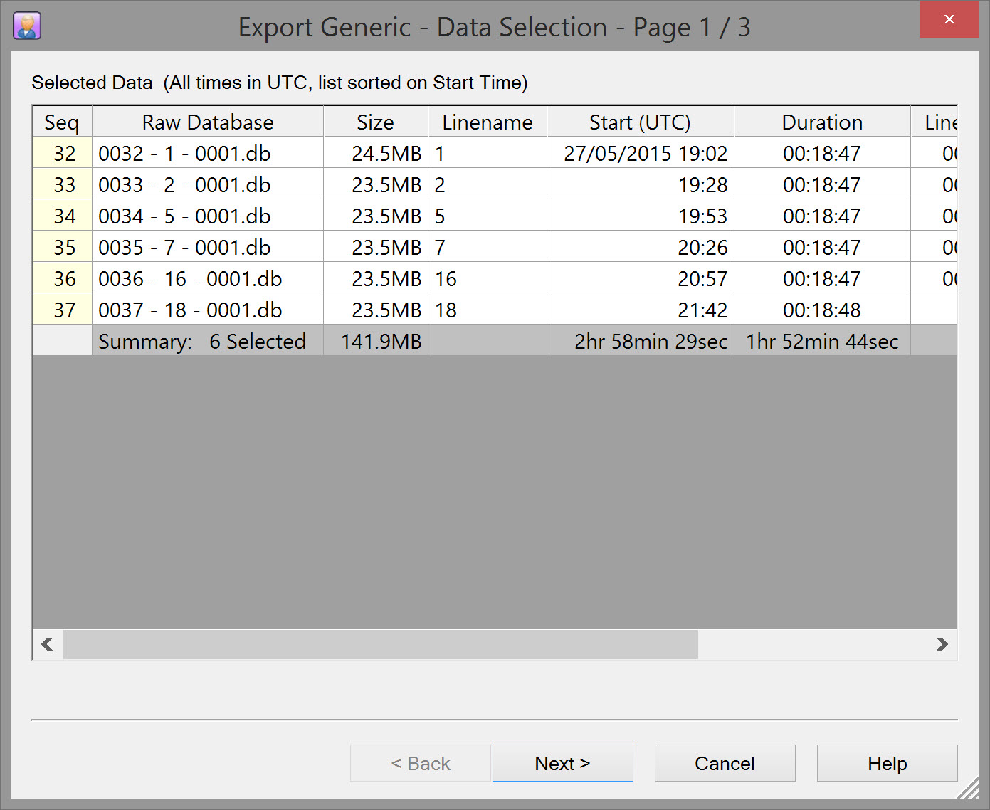
Page 1 - Export Generic-Data Selection
Displays the *.DB files selected in the Raw Data Manager.
Page 2 - Export Generic-Layout Selection
If not used before the Layout Selection dialog box is initially empty.
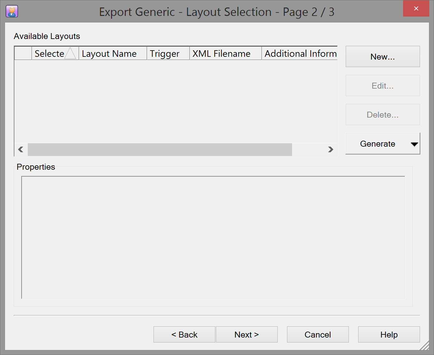
Click on 'New' to define a Layout XML settings file. This starts the Generic Layout Editor.
Generic Export Layout Editor - Overview
The 'All Data - Generic' application has four Layout Purposes, i.e. Driver, Display, Log File and Export.
When started from the Raw Data Manager 'Export - Action' the layout purpose cannot be changed from 'Export'.
General Layout Information
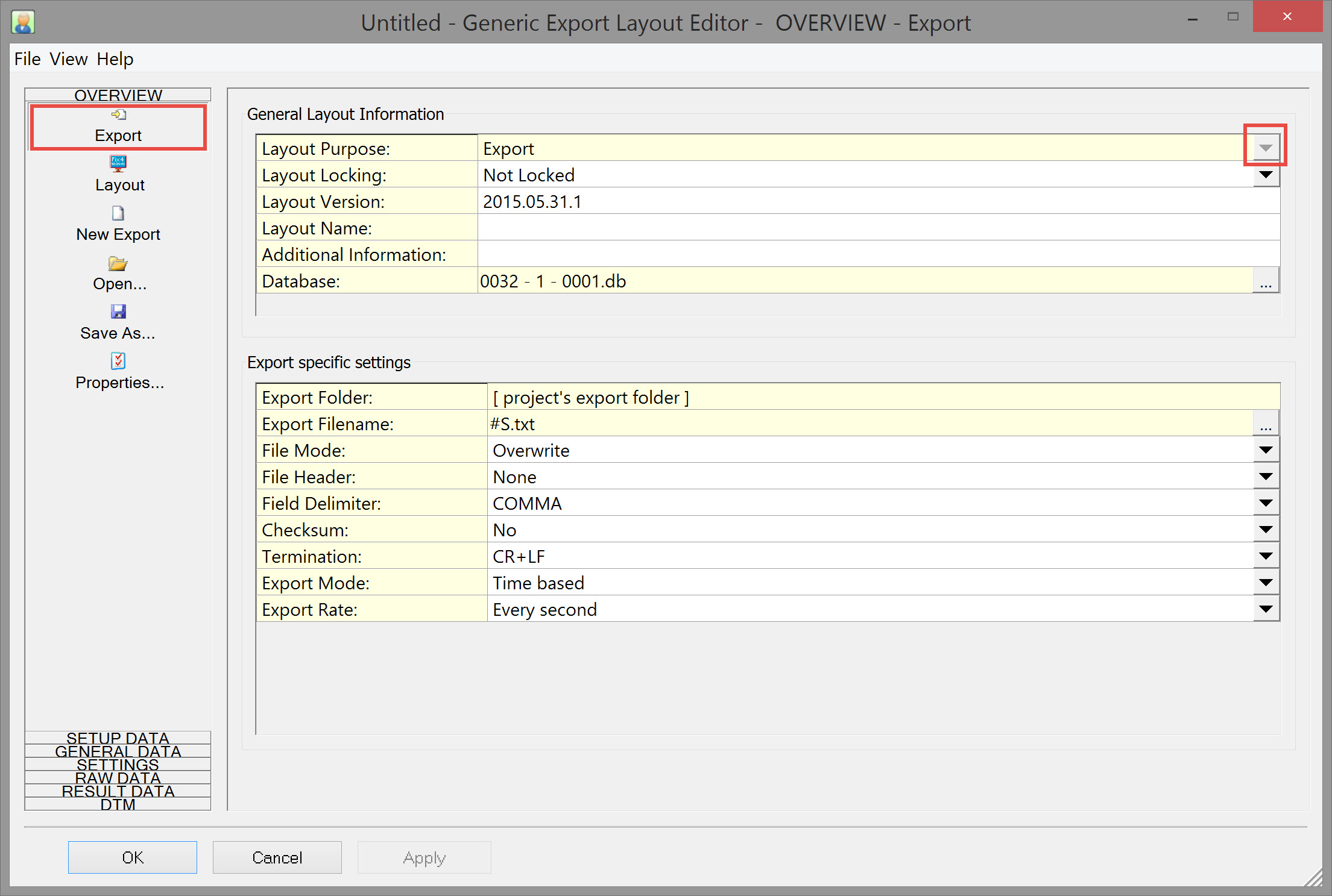
Layout Purpose: | The purpose of the layout can only be changed when the Generic Layout Editor has been started from the QINSy Console
|
Layout Locking: |
|
Layout Version: | Free text. Not mandatory |
Layout Name: | Free text. Not mandatory, but recommended |
Additional Information: | Free text. Not mandatory |
Database: | The QINSy database that is used to extract the data settings (e.g. which Node Id, System Id, etc) from.
|
Export Specific Settings
Export Folder: | By default this is the Project's Export folder. |
Export Filename: | By default is #S.txt where #S = Storage database file name. |
File Mode: | Select either 'Overwrite' or 'Append'. |
File Header: | A file header may be specified. Select one of: Non; Simple (all in one row); Simple (each item in one row); Reserved (kml). |
Field Delimiter | Select a field delimiter. Choices are TAB, SPACE and COMMA. If none of these are appropriate, select ADVANCED which adds the Advanced Delimiter field. |
Advanced Delimiter: | Opens the User defined Format Specifiers window. Click Add to choose one or a combination of delimiters. |
Checksum: | Option not really necessary for exporting data to files, but you never know... |
Termination: | For normal text files always select CR+LF |
Export Mode: |
Mode selected determines which fields are displayed below this one. |
Node: | Field is displayed when Mode is either Node based or Distance based. |
Computation: | Field is displayed when Mode is either Node based or Distance based. |
System: | Field is displayed when Mode is System based. |
Export Rate: | Field is available for all Export Modes. |
Another System: |
Generic Export Layout Editor - Node Output
Note on Text Formats that can be entered
In various places throughout the wizard, text may be entered in different formats.
Text Format:
- Normal Text
Your own free plain text Binary
Enter one or more ASCII character codes, comma or space separated, in the range between 1 and 127.
For example '2' for a binary STX character, '3' for a binary ETX character, or '13, 10' for CR+LF.
See tableASCII Codes for an overview of all possible characters.- New Line
Same as Binary, but already formatted as '13, 10' (meaning CR+LF) and without a possible Field Delimiter.
A Field Delimiter may be present when your layout purpose is for Export or ASCII Logging.
Info
Please refer to Nodes for further information.
Positioning data for vessel, guns, and receiver groups are the primary output for seismic surveys.
Nearly all the data is defined using the 'Nodes' button under the 'Result Data' side tab on the left of the Generic Layout Editor window.
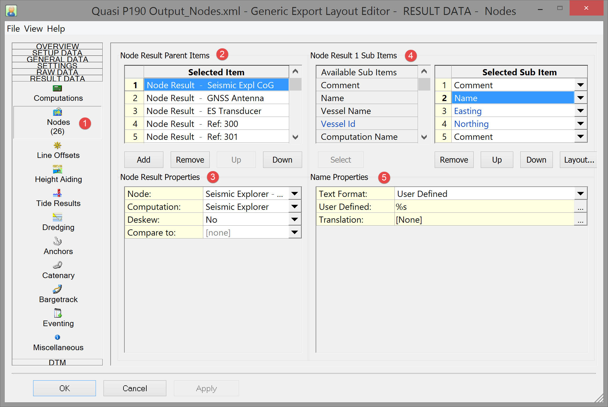

The sequence of adding nodes and defining properties is:
- Select the 'Nodes' button on the left under the 'Result Data' side tab.
- Click on 'Add' under 'Node Result Parent Items'. This adds a blank entry under 'Node Result Properties'.
- Select the appropriate node and determine whether the position should be deskewed to the time of Fix.
- Select the Node result Sub Items, by double clicking on each item.
- Define the Properties of each sub item.
Info
Note that when defined as 'New Line' the Comment field can be used to insert a blank line in the ASCII output file.
It serves a useful formatting function.

Continue to Add nodes. For seismic this would typically include:
- Vessel CoG
- Vessel GNSS Antenna
- Vessel Echosounder
- Guns (1 & 2 in the example)
- Receiver Groups
Other important output items for seismic are Fix Number and Fix Time. 'Fix Info' items are accessible under the 'General Data' side tab.
Number and Time should be sufficient.
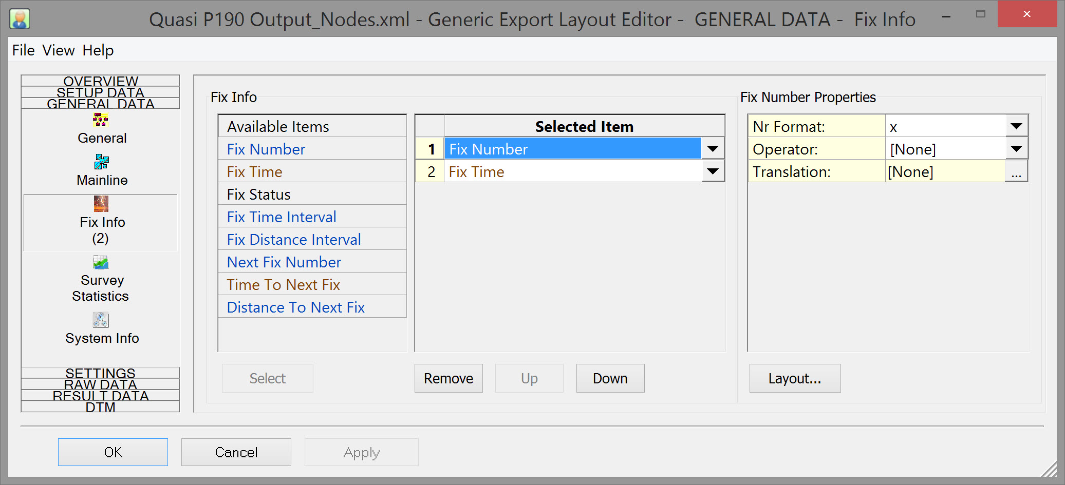
A final Layout might look something like this:
Example Layout Editor selections
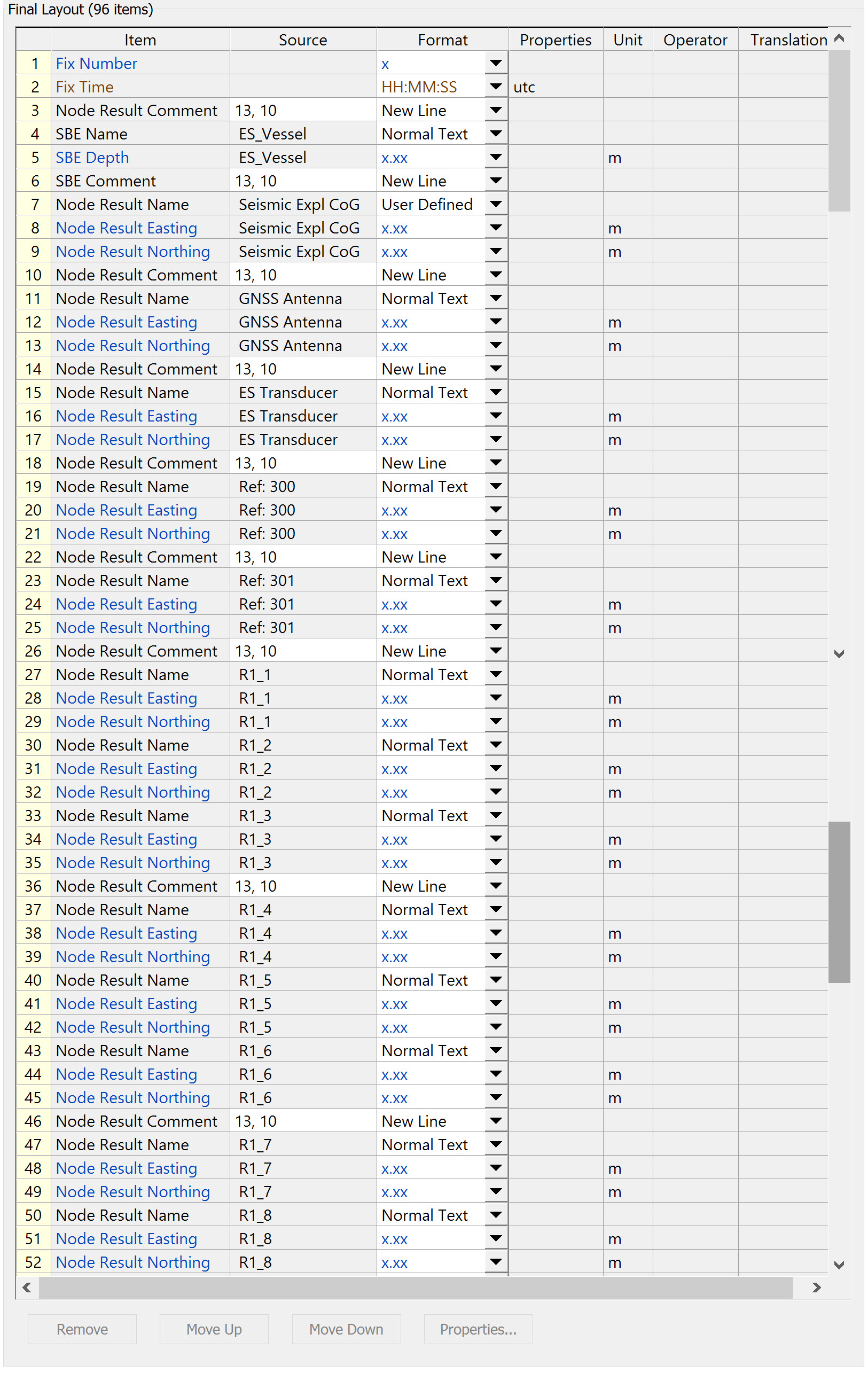
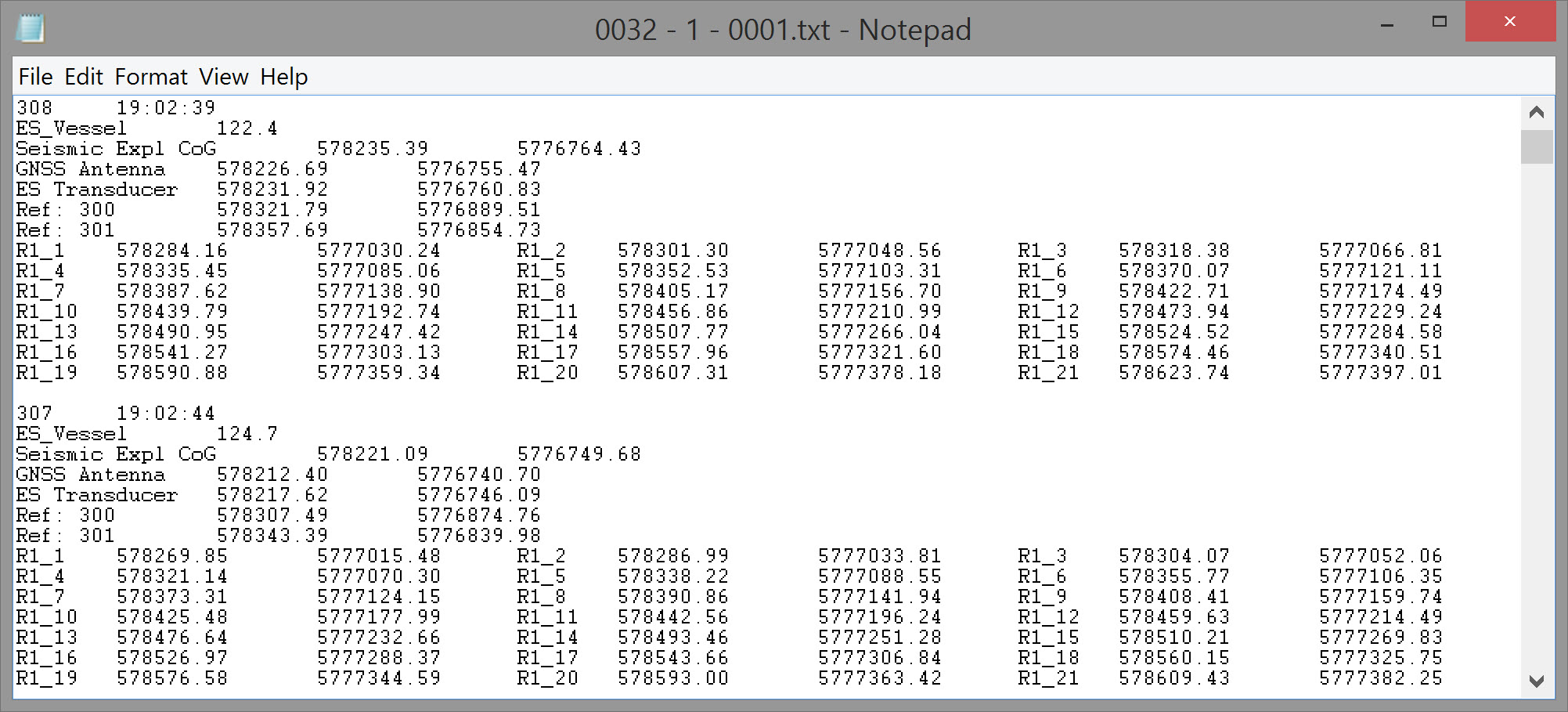
Note that Receivers have been grouped to export as three Receivers to a line by inserting a 'New Line' spacer every third Receiver.
Example Text File Layout:
Generic Export Layout Editor - Header Output
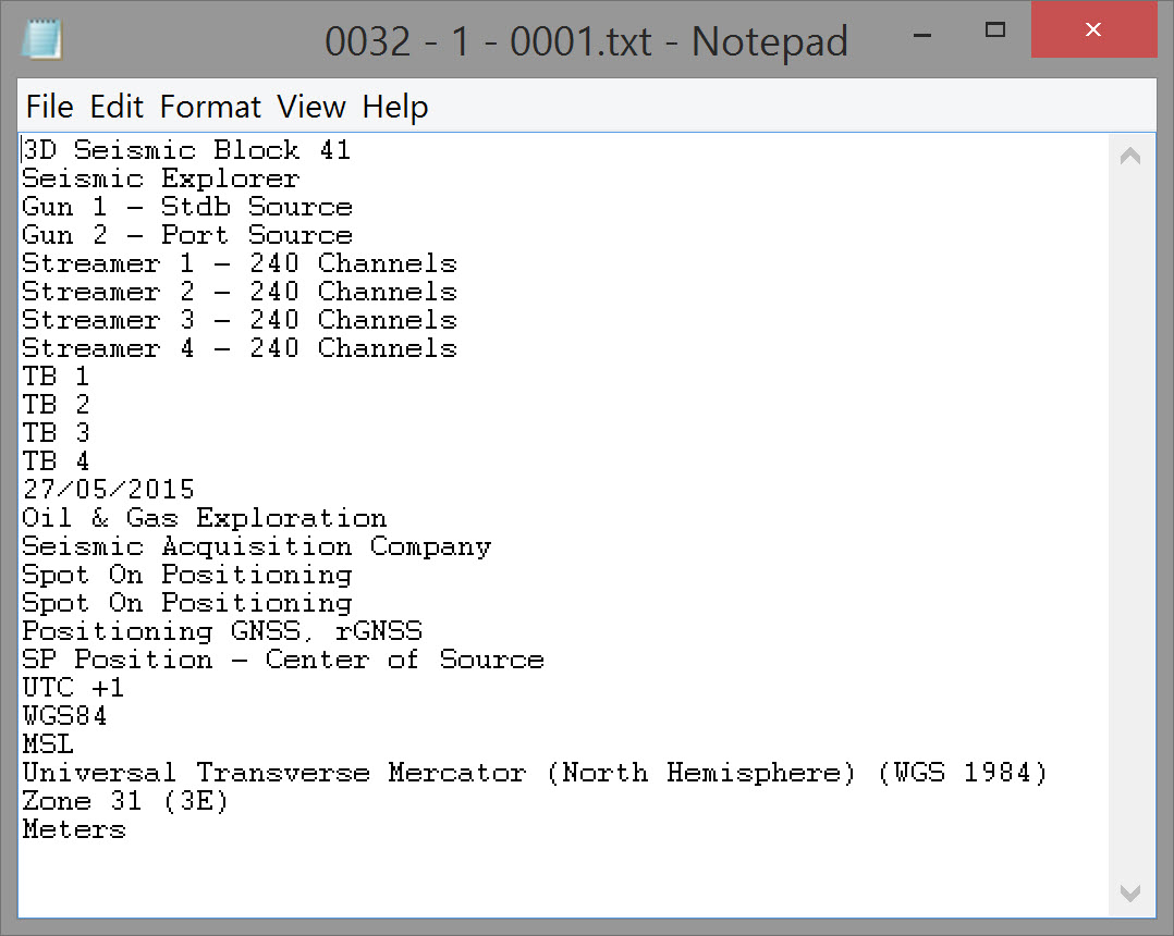
Perhaps of lesser importance but included here for completeness, it is also possible to output a 'Header' file which can be made to resemble a P1/90 header.
Setup Data - General
Info
A true P1/90 header cannot be fully replicated using the Generic Layout editor but the four options under 'Setup Data' (General, Geodetic, Object, and, to a lesser extent, Fixed Nodes) provide most of the information that appears in a P1/90 header.
See below for an example setup and exported file.
If exporting a quasi P1/90 format, almost all of this data would be part of the P1/90 header records.
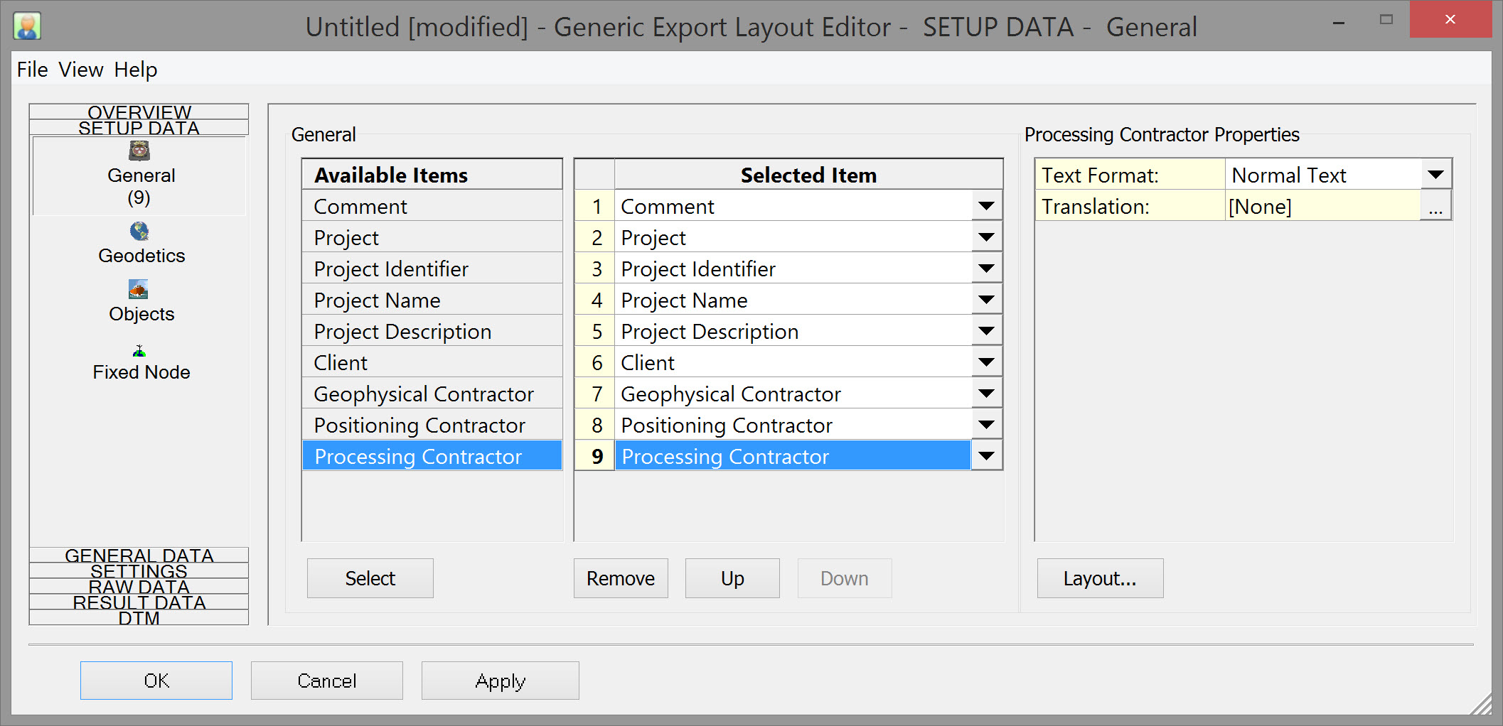
Information generally drawn from items entered in DbSetup, under the General Tab, with options to add more information here.
Double click on an item under the Available Items list to add it to the Selected Items list.
Refer to General for more details.
Setup Data - Geodetic
If exporting a quasi P1/90 format, almost all of this data would be part of the P1/90 header records.
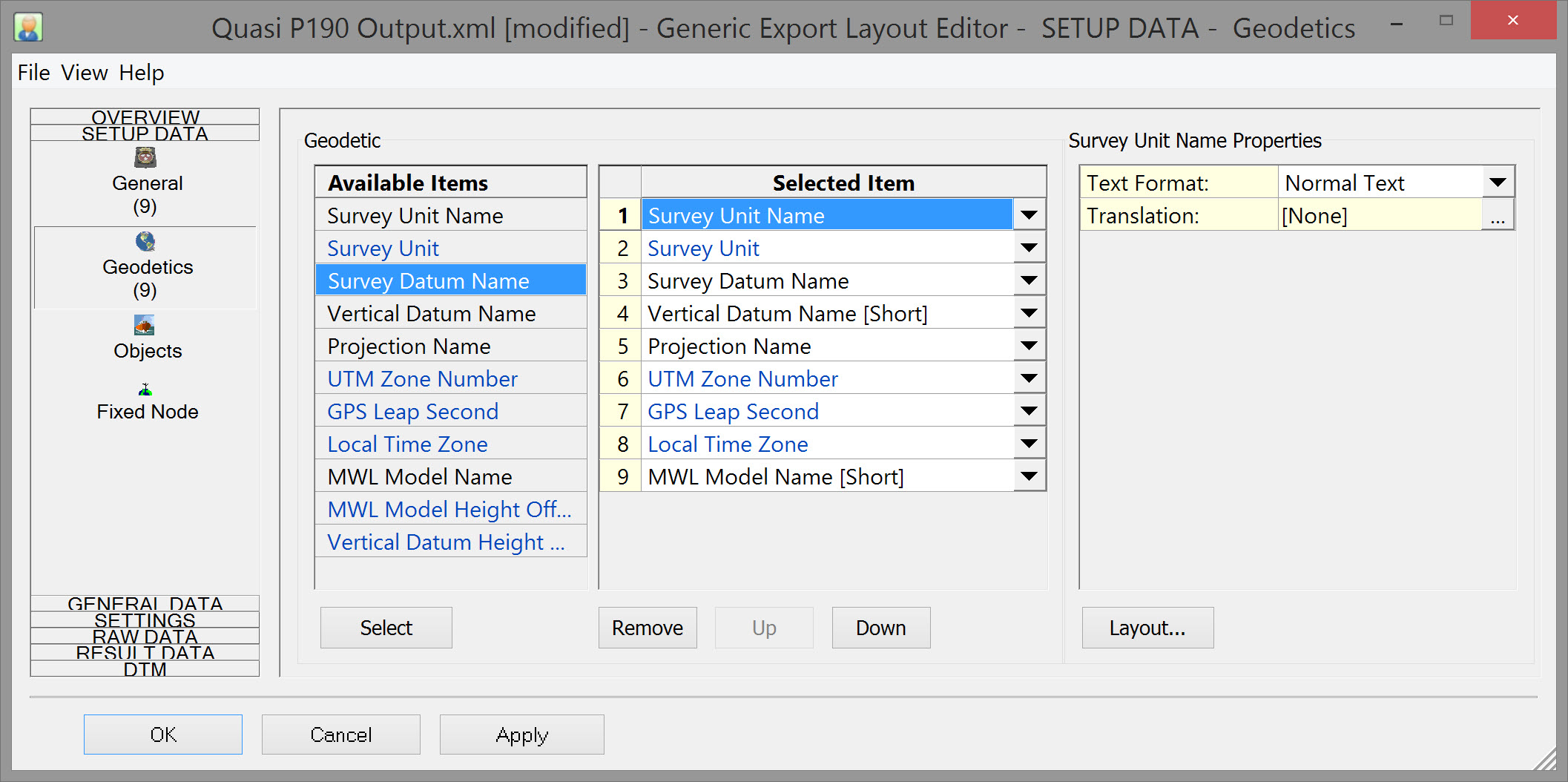
Information generally drawn from items entered in DbSetup, under the Geodetic Tab, with options to add more information here.
Double click on an item under the Available Items list to add it to the Selected Items list.
Refer to Geodetics for further details.
Setup Data - Object
If exporting a quasi P1/90 format, almost all of this data would be part of the P1/90 header records.
Press the 'Add' button to list 'Vessel Parent Items'. For each 'Parent Item' define the 'Vessel Properties', which is the name of the Object as entered in DbSetup.
For each vessel (object), double click on any of the 'Available Sub Items' to add it to the list of 'Selected Sub Items'. For a seismic header this would typically be the 'Name'.
Name may be modified under 'ID Properties' below. In the example S_1_1 is the name given to a towed object in DbSetup, i.e. the foremost section of Streamer #1.
By selecting 'User Defined' for 'Nr Format:' the name has been modified to 'Streamer 1' .
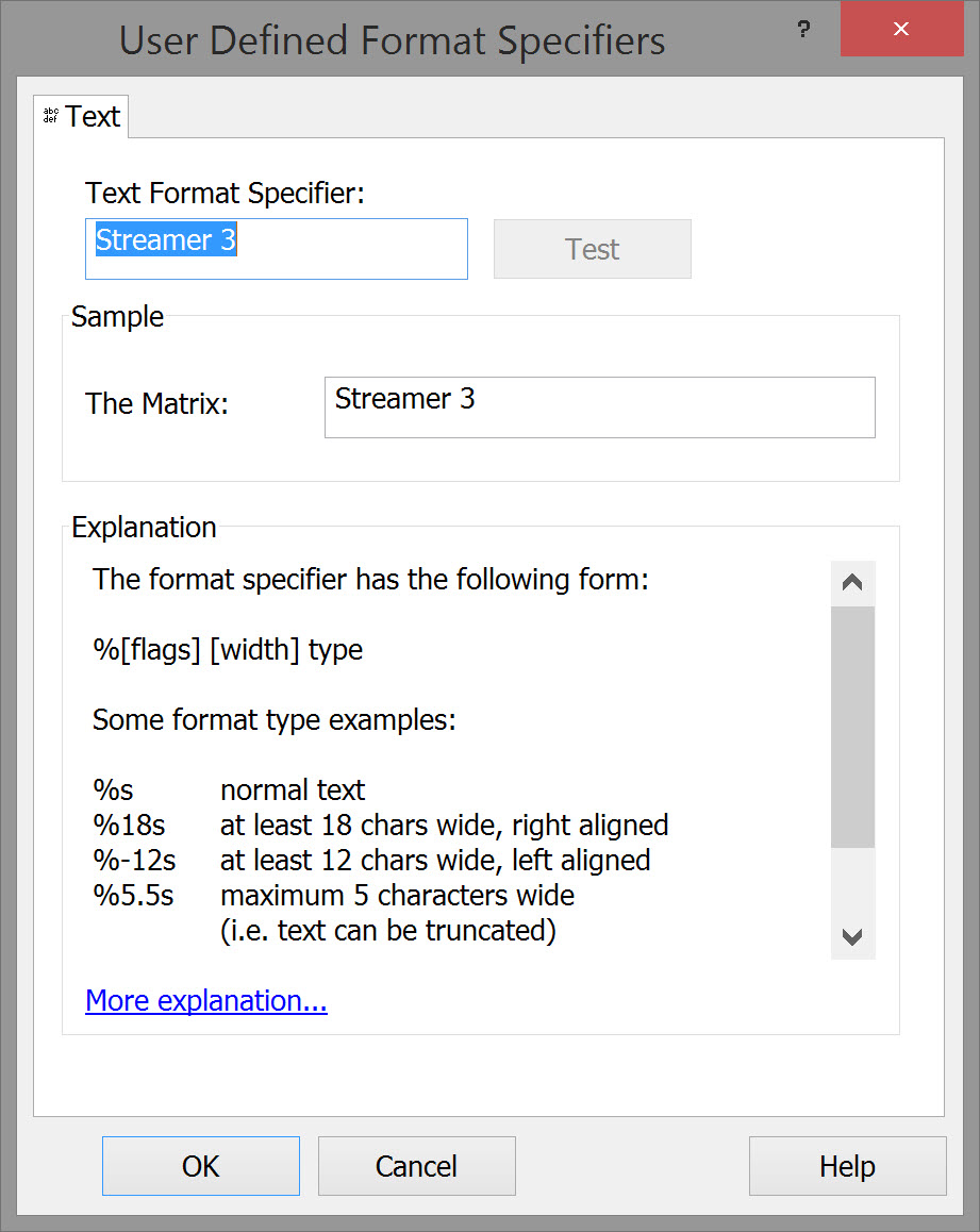
Refer to Objects for further details.
Setup Data - Fixed Node
According to UKOOA P2/94 format -
Fixed nodes (record H5000):
Record H5000 should be used to define fixed nodes, such as shore stations of radio positioning systems. Also moored buoys for which the co-ordinates are assumed to be fixed, should be defined using this record.
The co-ordinates of fixed nodes must be defined on the Survey Datum.
Heights need only be supplied when relevant to the position calculation.
Heights for nodes under the height datum, e.g. LBL acoustic beacons on the sea floor are negative and the sign should be included in the field.
Heights should be above sea level (code 3) in the case the node is mounted on a fixed moored buoy.
GNSS has largely replaced radio navigation systems so in modern times this would refer maybe to tide stations, or acoustic transponders in a fixed array.
Refer to Fixed Node for further details.
Example Header Output
Layout for Header output
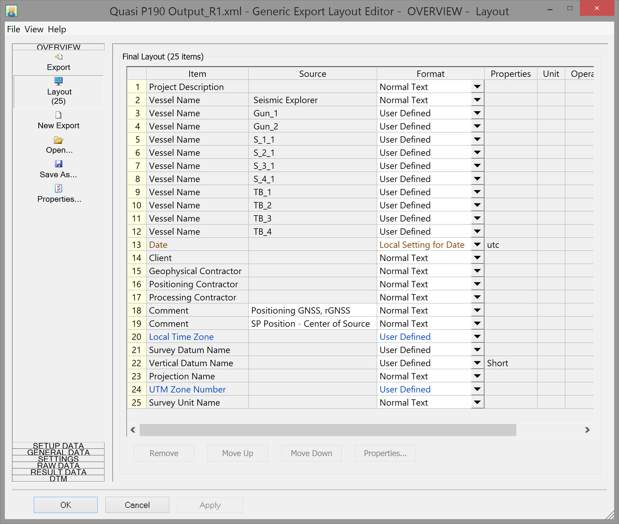
Header Output File:
Completing the export
After saving the Layout XML file, it is listed on Page 2 of the Export Generic - Layout Selection wizard. There may be more than one XML defined and saved.
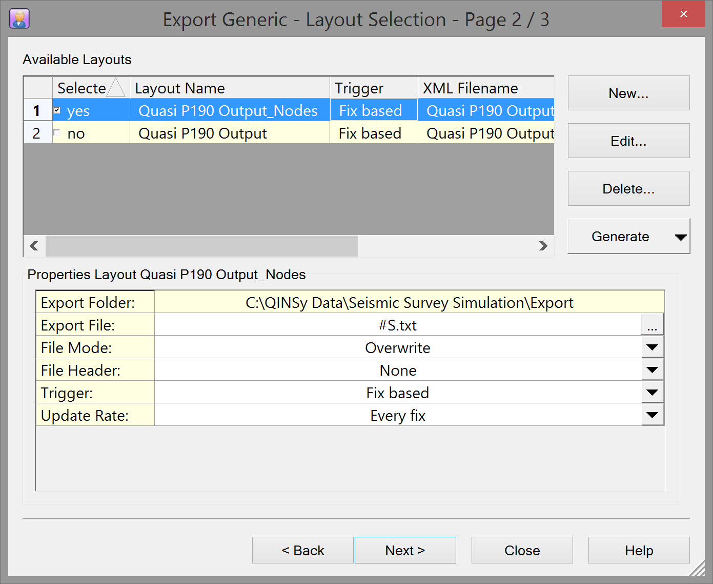
Click on Next and Finish on the third page of the Wizard to export the file.
Return to: Exporting Towed Streamer Seismic Positioning Data
