
Anchors
This is where the anchor spread is configured, including settings to store all anchor actions and anchor positions.
It is also used in actual running of anchors, especially the Anchor Setup dialog, where anchors are assigned to tugs and actions such as 'drop' and 'pickup' are initiated.
It is only available when a Tug Manager Output System has been added to the Database Setup.
To see this option make sure to first enable 'Show Anchor Setup' in the Settings - Session Shortcuts menu.
There are four buttons under the main 
|
Anchors |
|
|---|---|

Settings |
Enter settings to store all anchor actions and anchor positions. |

Rig and Tug Setup |
Configure vessels and tugs which will be involved in the anchor procedures.
|

Anchor Setup |
Set up and manage the anchors. |

|
Generate anchor positions based on the planned position of the barge. |
Settings

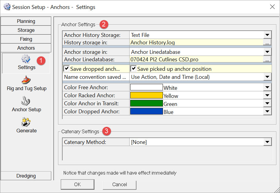

Anchor status and position are stored in an Anchor History log file. Drop and Pickup locations can also be stored in a *.qgf line database file, either the same database in which all main lines, routes and points are stored, or a dedicated database for anchor positions.
Positions may be stored with either UTC or local time, e.g
-
Picked up
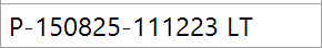
-
Dropped
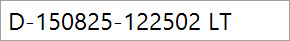
The addition of a sequential counter is optional.
Anchor icons and the 'rubber band' lines connecting objects can be displayed in different colors referenced to anchor status, i.e. Free, Racked, In Transit, or Dropped.

Return to: top of page
Rig and Tug Setup
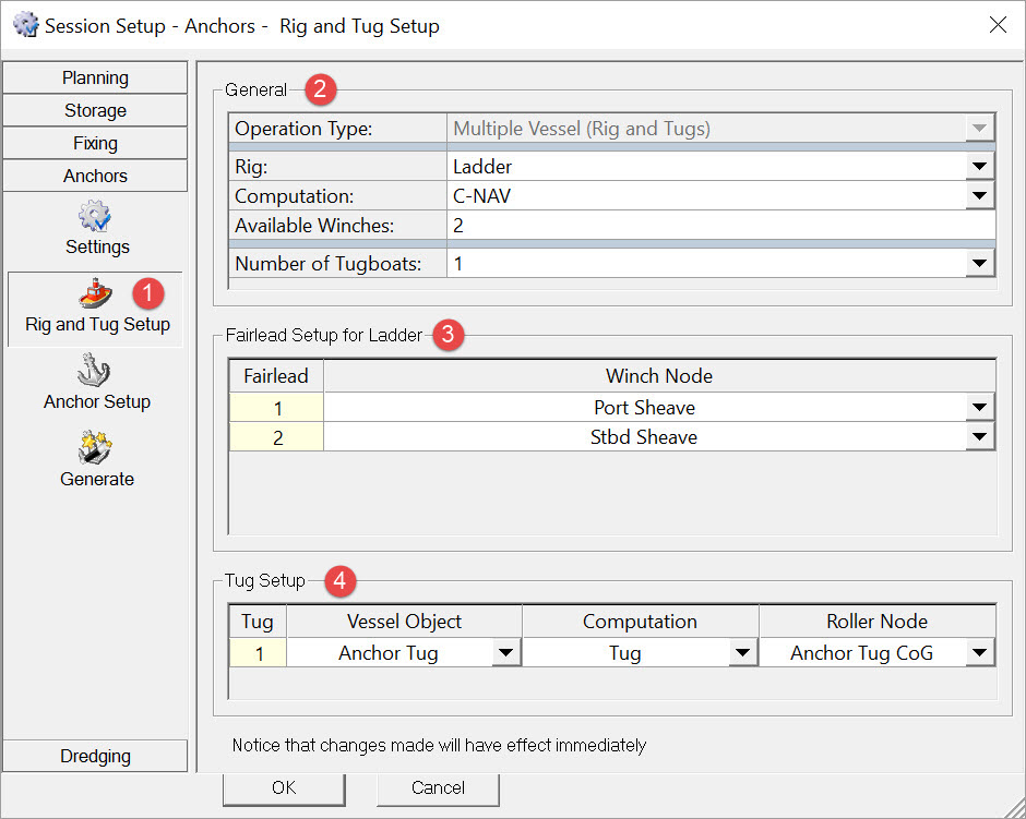
Either the dredger itself deploys and recovers anchors (One Vessel, No Tugs),
or one or more tug(s) are used to ferry anchors from the dredger (Multiple Vessels (Rig and Tugs)).
Note that this selection can only be changed when no anchors are defined on the Anchor Setup page so make sure to remove any that are listed in that page.

Return to: top of page
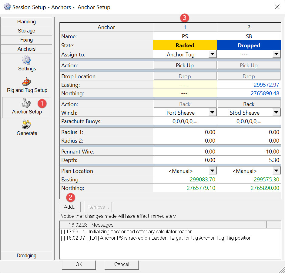
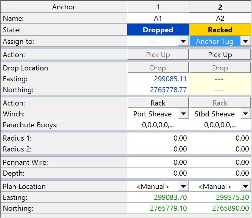
Anchor Setup
This is also the page open when running anchors..
|
Setting |
|
|---|---|
|
State |
First assign a winch node to each anchor. Anchor State changes to 
. |
|
Name |
Next give each anchor a name. |
|
Plan Location |
Define where the anchors should be dropped. Planned locations may already exist in the line database file selected under Anchor Settings or can be Generated. If so select the appropriate planned locations.
|
|
Radius 1 & 2 |
Two circles can be drawn around each anchor. Because they move along with the anchor when it is being re-positioned, they are useful in the Navigation Display when obstructions/hazards on the seabed must be avoided by certain distances.
|
|
Assign to |
The next step is to assign a tug to an anchor. State changes to 
. |
|
Action |
The Action button becomes live, initially showing Range markers may be set in the Navigation Display to show bearing and distance between winch and tug, winch to planned drop, and tug to planned drop. |
|
Drop Location |
This button becomes live Drop location coordinates are updated automatically. |


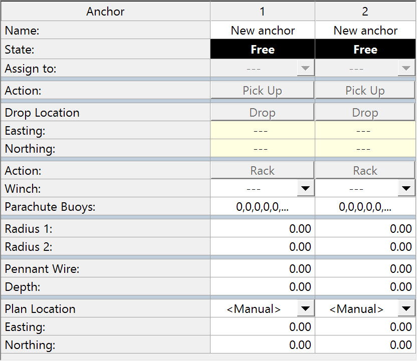
Having completed the drop for one anchor, assign the tug to the second anchor. The dialog now looks like this:
Further picking up and dropping is a repetition of the above.
Parachute buoys are not normally used in dredging operations.
Pennant wire lengths are not normally of concern either.
Please refer to the Navigation Display section for information about displaying anchors.
Return to: top of page
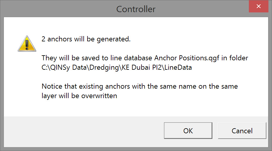
Generate
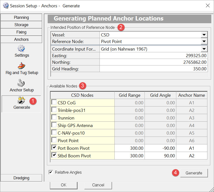
Enter predefined coordinates, either in grid or geographical format.
Typically the 'vessel' (object = dredger) also has a predefined heading.
These are usually the nodes from which the bearing and distance of anchor wires are measured.
Generate uses the ranges and angles entered to compute anchor locations relative to these fairlead nodes.
Angles used in the computation can be either absolute (referenced to north) or relative (referenced to the heading of the object entered above.
By default anchor names are assigned to each available node. Change the names for any activated nodes.
Return to: top of page
Return to: CSD - Session Settings