
How-to Height - Tide and RTK
This document describes how to obtain reliable heights with various types of positioning systems.
The How-to comprises three pages:
- This How-to Height with a general explanation
- The Height 2D -Tide- Settings mode document
- The Height 3D -RTK- Settings mode document
This first page includes:
ITRF
Throughout the text ITRF is used as a generic term that covers global and regional datums; for example ETRS89 and NAD83.
Height Conventions
Heights are positive upwards and depths are positive downwards.
Real-time Height
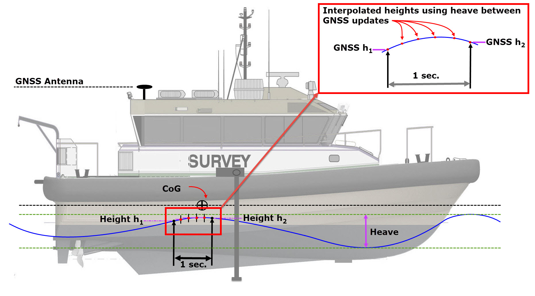
Qinsy always uses the object’s reference point for rotations and heights. The Least-Squares Adjustment (of raw observations) computes the reference point, the Position Filter process filters the reference point, and the Multibeamer process computes the transducer positions from this reference point too. In between reference position/height updates the Multibeamer uses the highest-priority active heave/bathy observation to interpolate the reference node height, applying a scale factor so that that delta observation fits the before and after node heights computed by the Adjustment and Position Filter (see following image).
Five processes are involved.
- PreProcessor
This determines the attitude (heading-pitch-roll) and height observations to be used. - Height Aiding
The height Aiding driver computes the raw object heights (if no accurate heights are available), It computes the value of the so-called 'Height Aiding Observation'. - Adjustment
The Adjustment computes all raw object node positions (including the reference point). - Position Filter
The Position Filter, filters/predicts the reference point (position and/or height) and shifts all the other object nodes. - Multibeamer
The Multibeamer computes the transducer (transmit/receive) positions for the echosounder ping times as well as the footprint locations.
Traditional (2D) Hydrographic Surveying vs RTK (3D) Surveying
The accuracy of the measured height is important if a correct representation of the seafloor is to be obtained.
When calculating the height of the transducer above the local vertical datum, two situations can be distinguished:
- 3D Positioning (height status = accurate)
- 2D Positioning plus Tide (height status = unreliable)
How Qinsy handles each situation is described in the sections below.
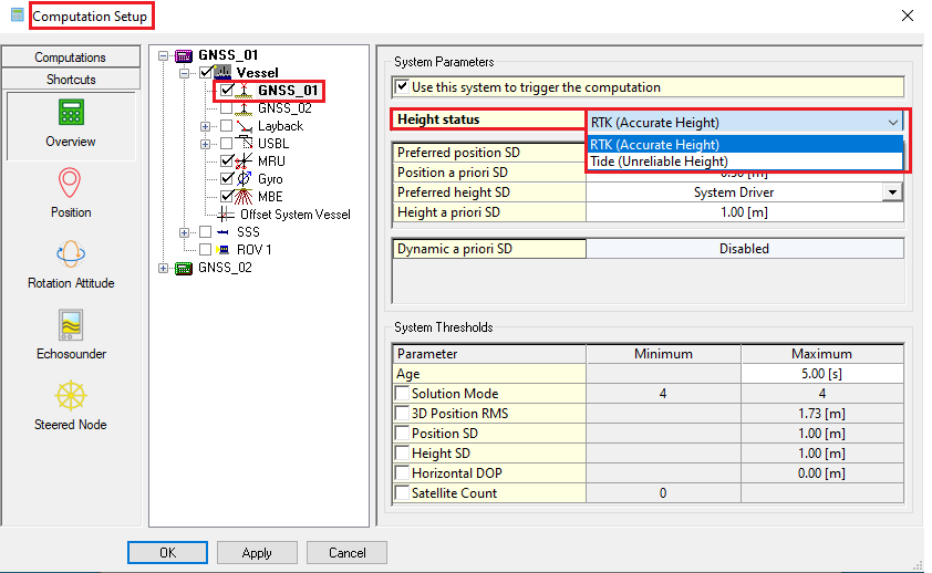
Height status
'Height Status' is set in the Computation Setup window accessed by selecting Computation Settings from the Settings menu in the Controller.
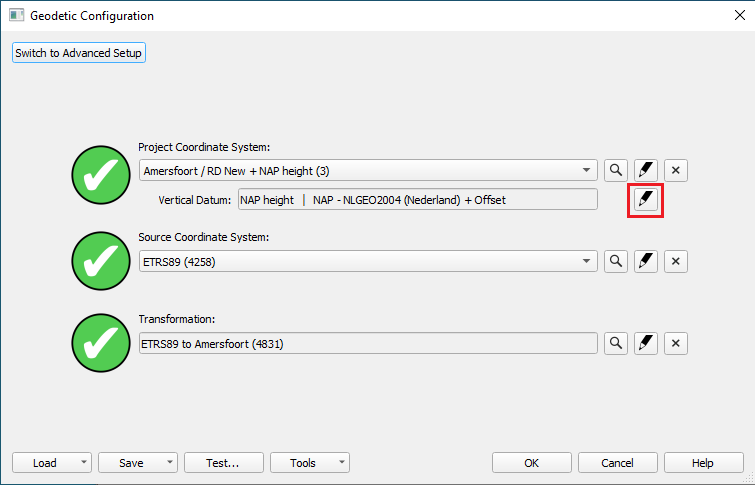
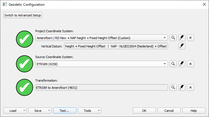
Datum Transformation
Grid coordinates are always calculated and visualized on the selected survey datum. In case a GNSS positioning system is used, the position is commonly measured in ITRF/WGS84. When one of these is not selected as the survey datum, a datum transformation to the local survey datum is required.
For both 2D and 3D positioning methods it is necessary to do a datum transformation first. In the positioning system a source datum is defined (most often ITRF/WGS84) and this needs to be transformed to a local datum.
This is done via a datum transformation: the resulting latitude, longitude and height are then referenced to the local datum.
Height Concepts - Height Aiding and Chart Datum
First it is important to realize that we are dealing with 2 different concepts, i.e. Height Aiding and Chart Datum.
'Height Aiding' means to “aid” the computation of the 'height' of a node position by adding an additional observation, i.e. the height aiding observation, to the adjustment in which the node position is determined. Height aiding is typically required when the height component of position is insufficiently accurate for the particular survey purpose. For example, DGPS is not usually accurate enough for precise bathymetry. Height aiding is also used in computing position of an underwater object (towed fish/ROV) when observation(s) relative to water level are available, e.g. ROV depth, even when the 3D positioning of the surface vessel itself is accurate to centimeter level.
Survey datum
However, even when height aiding is used, all the resulting heights computed in the adjustment are still given with respect to the survey datum that has been selected on page 1 of the Geodetic wizard in Database Setup.
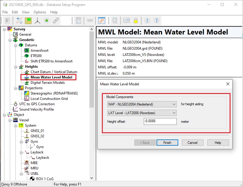
A "Mean Water Level Model" (MWLM) is used as the reference plane for height aiding observations which are used as input for the computation modules that are listed in the 'Real-time Height' section above.
MWLM is a geoid model, plus optional river line model, plus optional height offset, used in Qinsy to reduce tide observations to. It defines the common height level for the tide height values.
Height aiding observations
The sources of height aiding observations are listed below.
“Chart Datum” means that the resulting heights computed in the adjustment are published with respect to a datum other than the (survey) datum on which the positions are computed. Note that selecting a different datum as "chart datum", on page 3 of the Geodetic wizard, does not influence the computations themselves in which position and height are still computed with reference to survey datum, except as noted here.
Chart datum
Chart datum can be identical to the survey datum. In this case published heights are the same as those computed in the adjustment.
So 'Mean Water Level' refers to height aiding observations which are used as input for the computation modules listed in the 'Real-time Height' section above. Chart Datum refers to the published height results that are output from the computation modules.
MWLM and Chart Datum are often connected by using a common geoid model. Indeed, it makes no sense to use different geoid models for input and output. For a lot of surveys, MWLM can be chosen identical to the Chart Datum, especially when only relative heights are important. One common situation where MWLM and Chart Datum may be different is when '2D Positioning / Unreliable Height (Tide)' is used and height results are to be reduced to LAT, so the Chart Datum reference level is lower than the MWLM reference level.
Confusion potentially arises from the fact that both concepts can make use of the same (or even a different) geoid model. Moreover, the height aiding driver can also be used to compute heights with respect to the geoid (or more precisely mean sea level). However, the latter approach is only available if we have an observation that gives height data with respect to mean sea level, such as an ROV depth.
If we have position data that is accurate enough to compute precise and reliable heights, e.g. when using RTK, then we only need to consider the Chart Datum because all 3D positions are computed in the adjustment referenced to the selected Survey Datum and then results are published with respect to the selected Chart Datum.
If we have observations that give heights with respect to mean sea level, e.g. when using ROV bathy units, then we only use the height aiding driver and select the Chart Datum to be the Survey Datum. But if we want to improve the height results from the adjustment computations, e.g. when using DGPS, then we (can) use both the height aiding driver, to add more height information, and the Chart Datum, to apply a height offset to the results.
Both the Mean Water Level Model and the Vertical Datum / Chart Datum definitions consist of three parts:
- an absolute geoid model. Geoid separation is the height of the geoid (MWLM) above the ellipsoid (survey datum).
- a relative height correction model.
- and/or a manual height offset.
Both 'relative height correction model' and 'manual height offset' are used to adjust the MWLM. For example, a 'River Lines' relative height correction model might be used when surveying up a river. Or a manual offset might be used to adjust published depths when the Chart Datum is slightly different to the MWLM. Please refer to Help pages for more information on MWLM and Chart Datum components.
Return to top of page.
3D Positioning / Accurate height (RTK)
This method measures depths relative to the Chart/Vertical datum directly from accurate GNSS observations (RTK).
This means the water surface level is of no relevance anymore. Height offsets like tide, draft and height above draft reference are not necessary for this method and are not used to calculate the depths.
Computation Process
An RTK (or Total Station) is, for example, a system that provide an accurate height or a 3D position, outputting a position and height accurate to within a couple of centimeters.
On the vessel a local reference frame is employed that preferably uses the Center of Gravity (CoG) as its origin. All offsets of all sensors (GNSS antenna, echosounder transducer, etc.) are measured relative to that CoG.
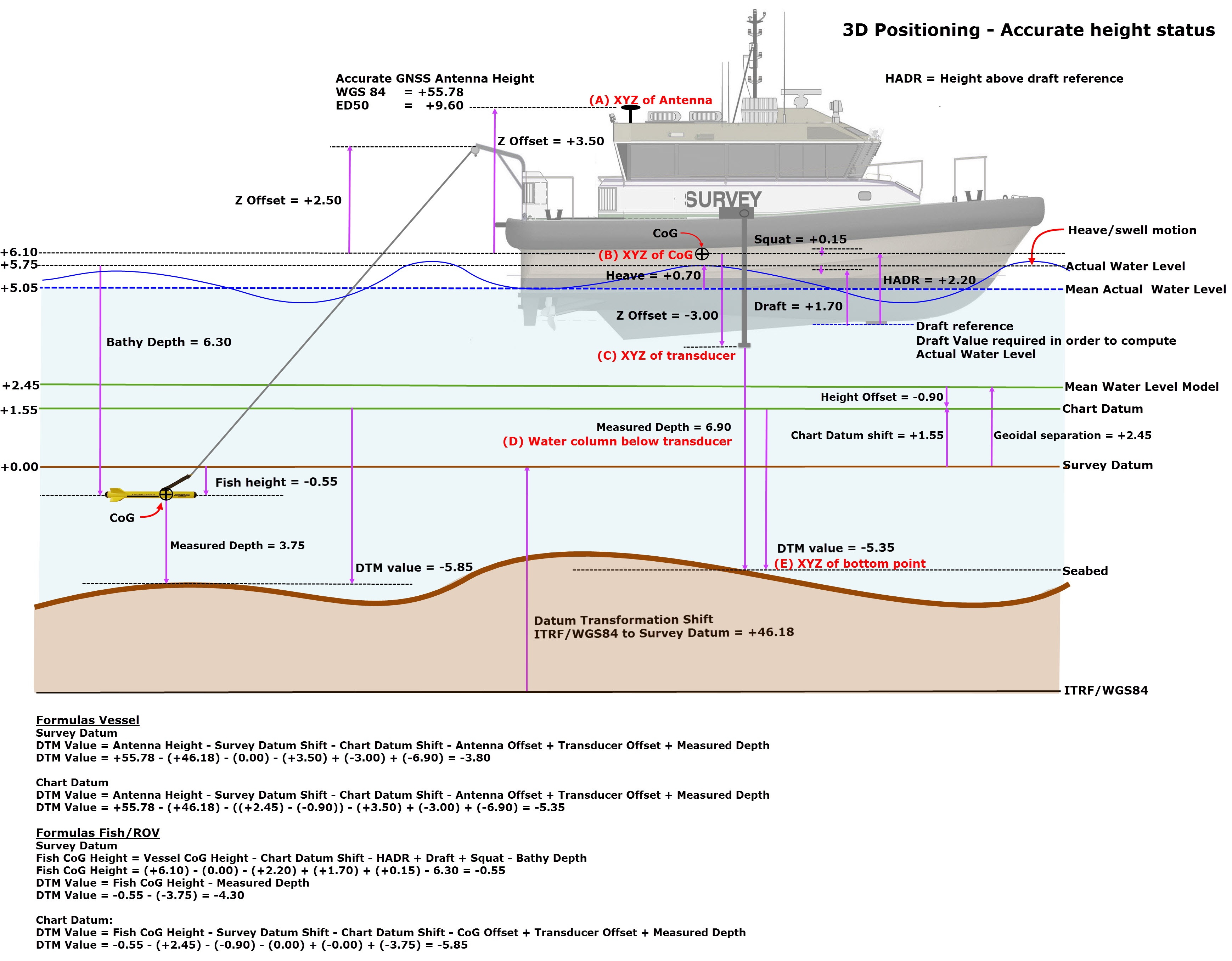
When the GNSS RTK positioning system measures the position and height it will provide the (almost) exact position and height of the antenna (see 'A' in the diagram below) in WGS84 coordinates (default datum in GNSS systems). As mentioned above this position is transformed to the local datum. Assuming that the exact offset from the antenna to the CoG is measured, we know the position and height of the CoG (see 'B') in reference to the local datum.
Now we know the position and height of the CoG, we also know the height of the echosounder tranducer (see 'C') (and all other sensor offsets) relative to the local datum.
The echosounder transducer measures the distance to seafloor below the transducer (see 'D'). Combine that distance with the transducer height and you know the position and height of the measured seafloor footprint (see 'E') relative to the local datum.
Many GNSS systems update position at only 1 Hz. In order to calculate height of the CoG at a higher frequency than position updates the heave observation from a motion sensor is used. Heave values are only used to calculate the height of the CoG between two position updates (see Real-time Height above)..
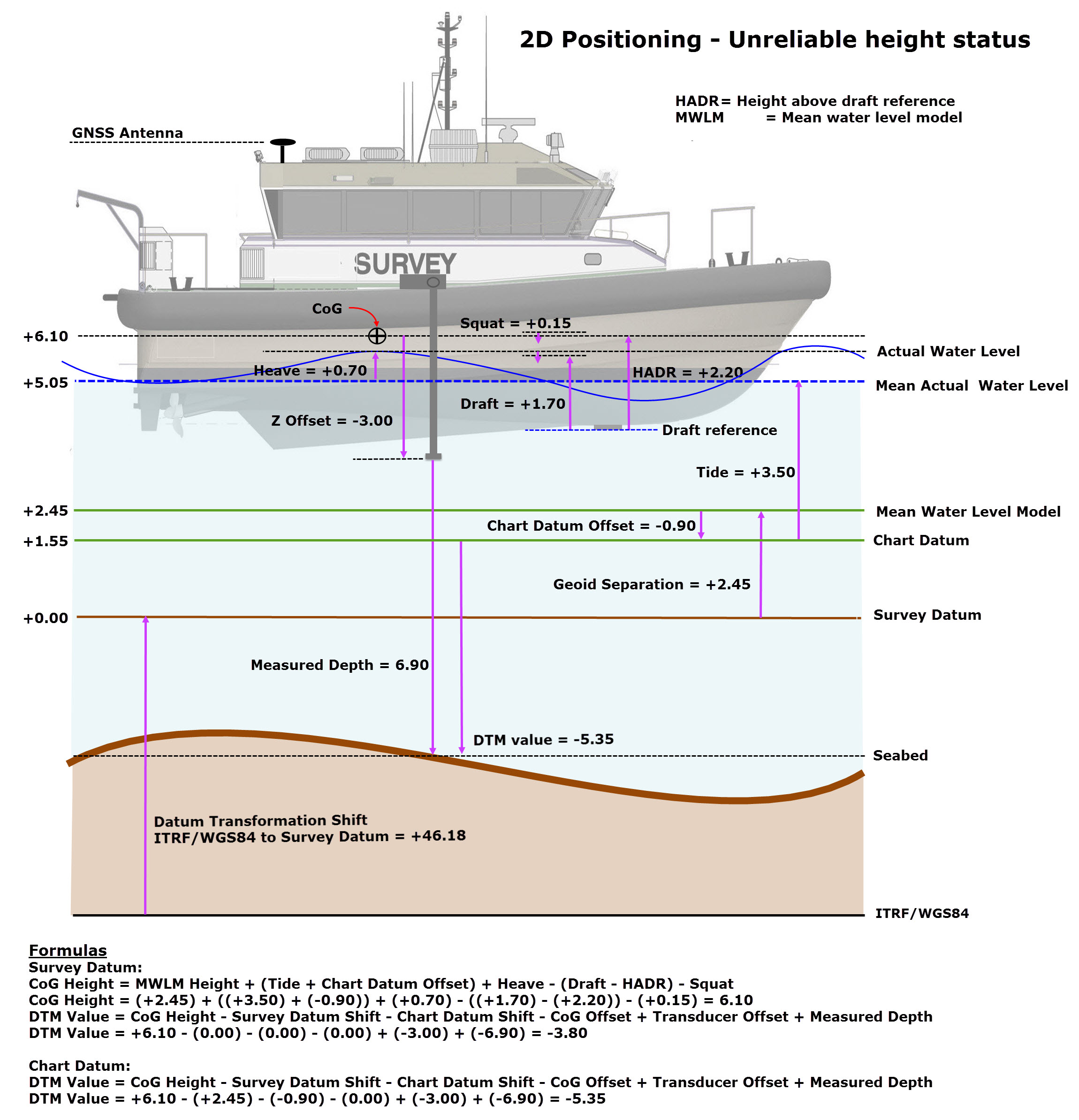
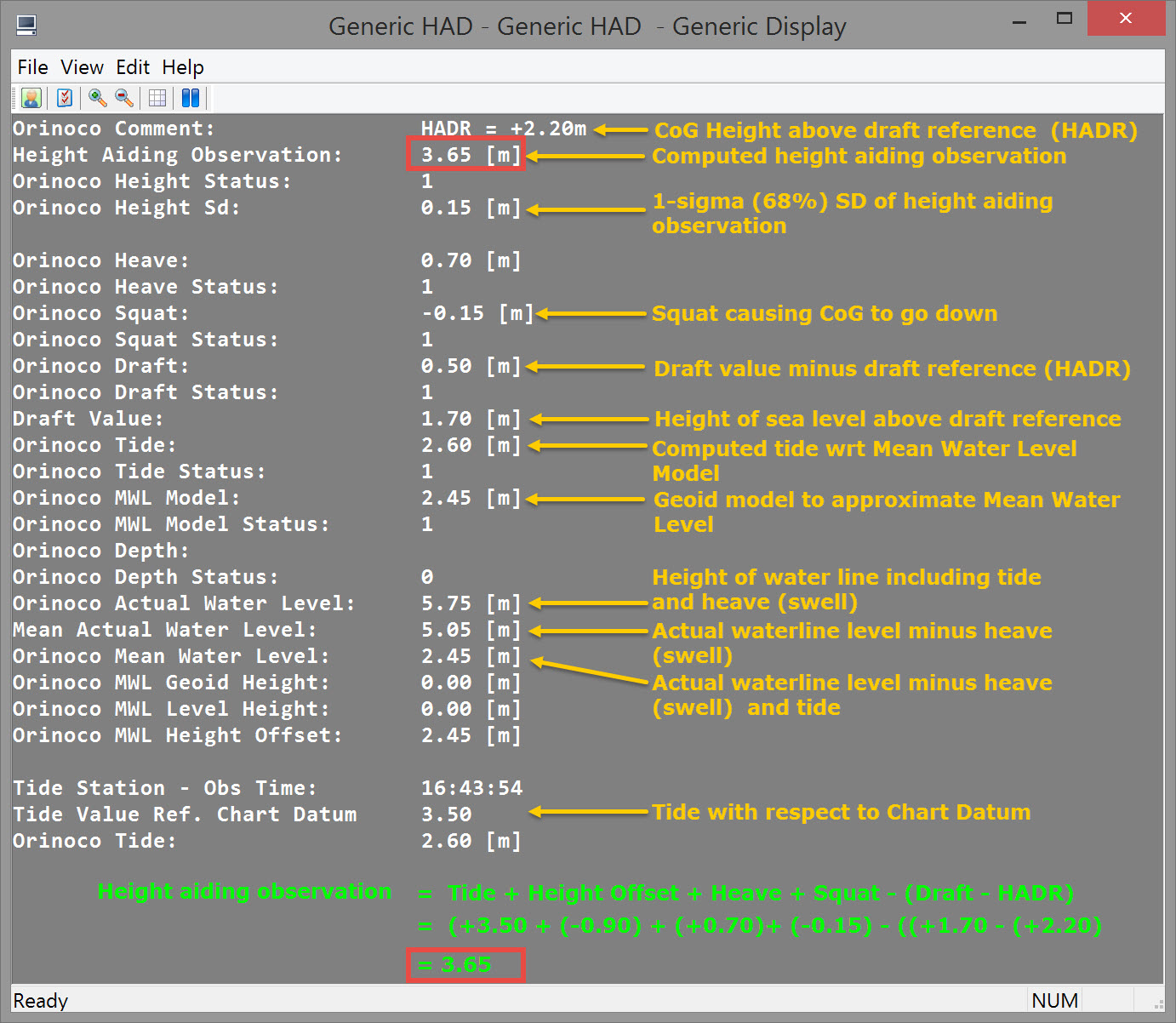
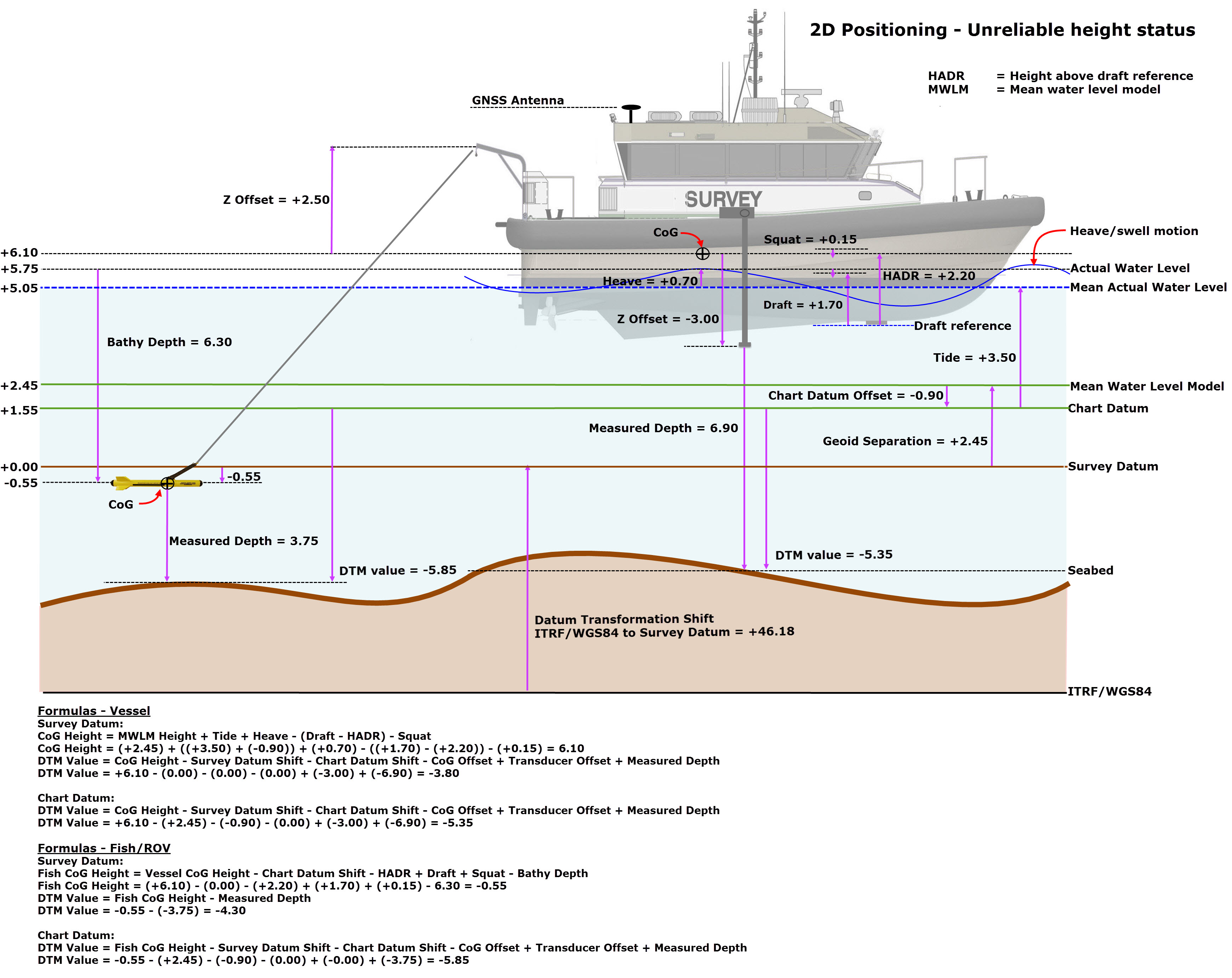
Parameter values from a simulated project are presented in the figure below to clarify the computational process.
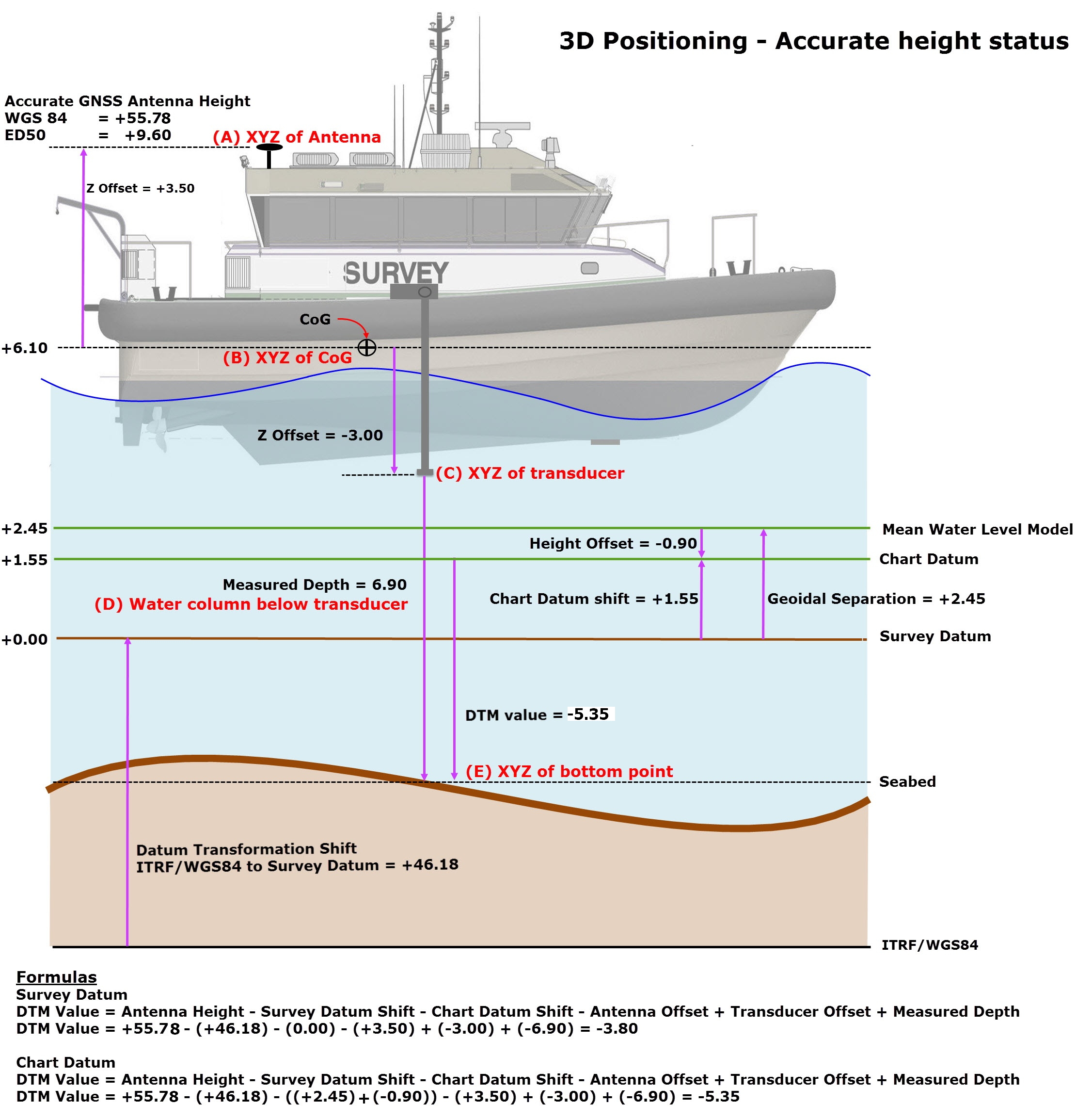
In the uppermost formula above, the computational result is with respect to Survey Datum. Hence 'Chart Datum Shift' equals zero and the computed DTM value is -3.80.
The two other formulas represent selection of another datum (MWLM or Chart Datum) used to publish a DTM value. Hence a 'Chart Datum Shift' with respect to Survey Datum is applied.
In other words, the computation result is always referenced to the Survey Datum selected in DbSetup and a 'Chart Datum Shift' is applied if DTM values are published referenced to another datum.
Vertical position of the vessel on the water level
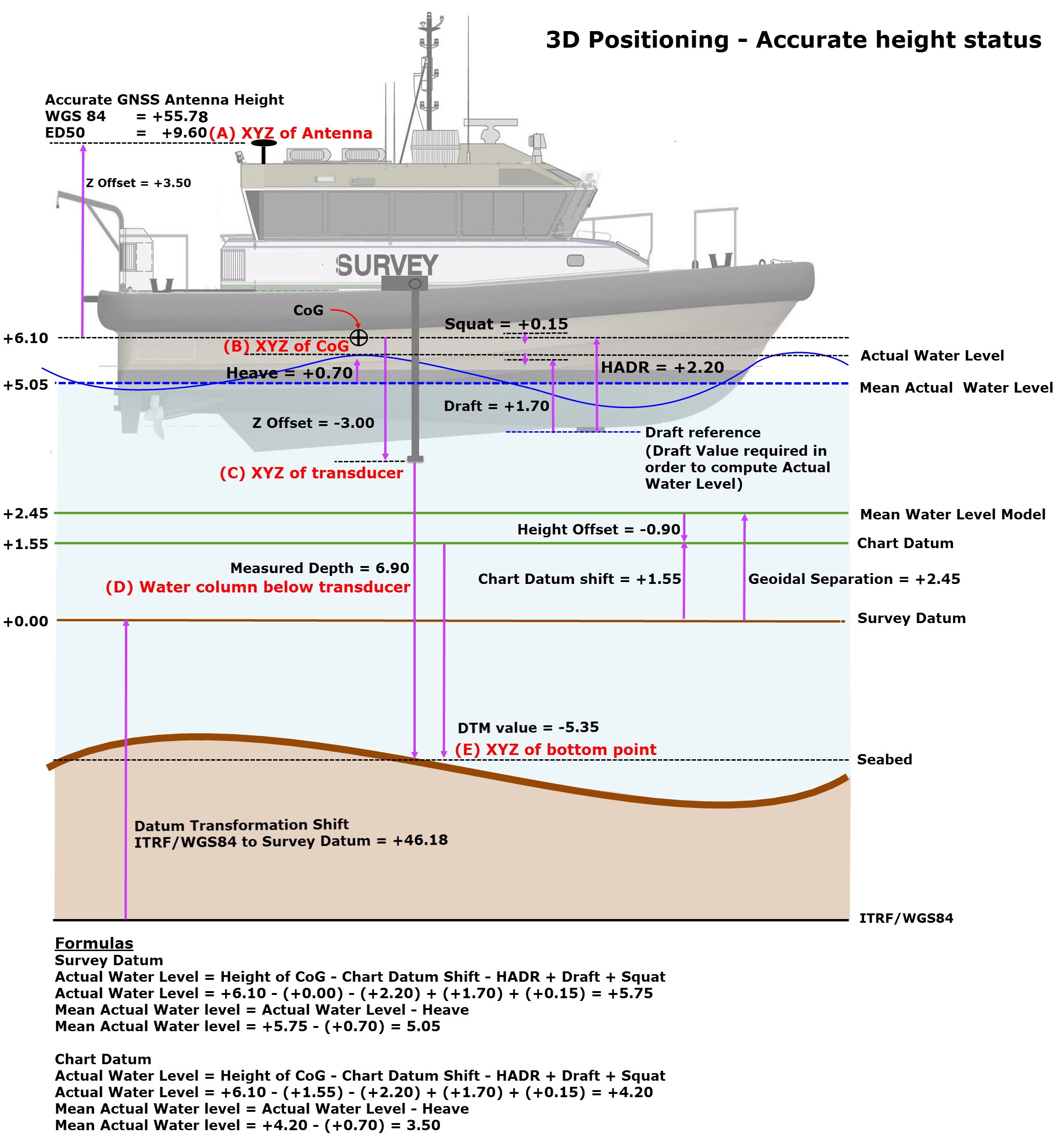
As noted above, water surface level is not directly calculated in accurate 3D positioning. However, in some circumstances a knowledge of water level is needed; for example, when a towing vessel is accurately positioned with RTK and the 3D position of a towed object, or ROV, is required, the actual water level must be determined by the survey vessel because the measured depth of the towed fish, or ROV, is referenced to water level. In another example actual water level is needed to determine loading of a dredge hopper.
When draft/depth sensors are used (defined in Database Setup) in combination with a GNSS providing accurate height, it is possible to calculate a Water Level height. This Water Level can be used in Height Aiding to determine the height of towed objects, ROVs, hopper loading etc.
The following diagram illustrates the computation of water level:
Delta Height of Vessel CoG
'Delta Height', is the height difference between an accurate height (e.g. from RTK) for a node and an unreliable height for the same node. Unreliable height is computed using database settings such as the mean water level model and object height settings as defined in the Computation Setup (see 2D Positioning plus Tide / Unreliable Height below).
Continuing with the example scenario used above, height status is set to 'accurate' and no HADR, draft, tide, heave or squat observations are enabled. The Height Aiding Driver window looks like this:
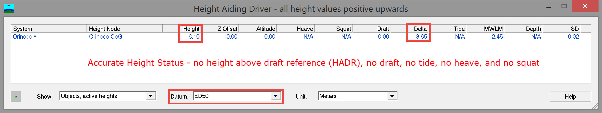
Delta height = 3.65
If height status is switched from 'Accurate' to 'Unreliable' and no other changes are made, the Height Aiding Driver window contains the following values:
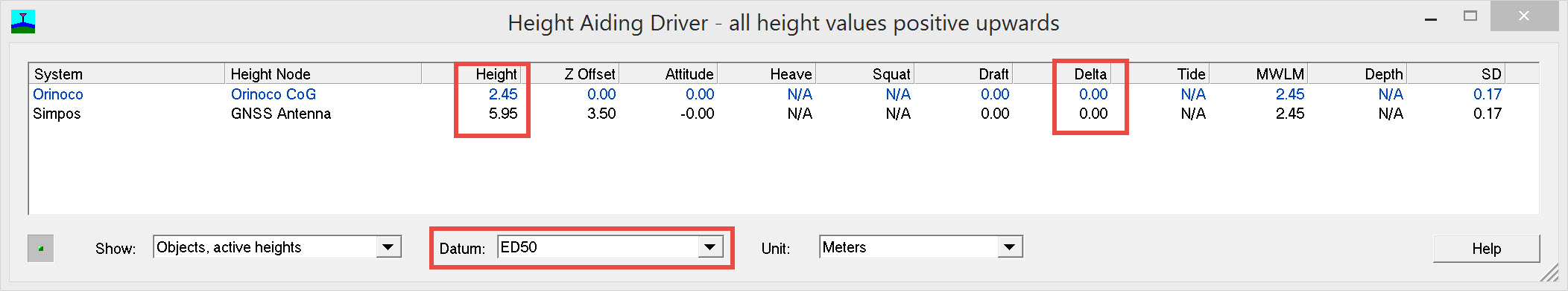
The shift in height for the CoG is
(+6.10) - (+2.45) = +3.65
which equals the Delta height value shown in the 'accurate' case.
With an 'unreliable' height status and with the usual height aiding components, HADR, draft, tide, heave and squat enabled, the Height Aiding Driver window contains the following values:
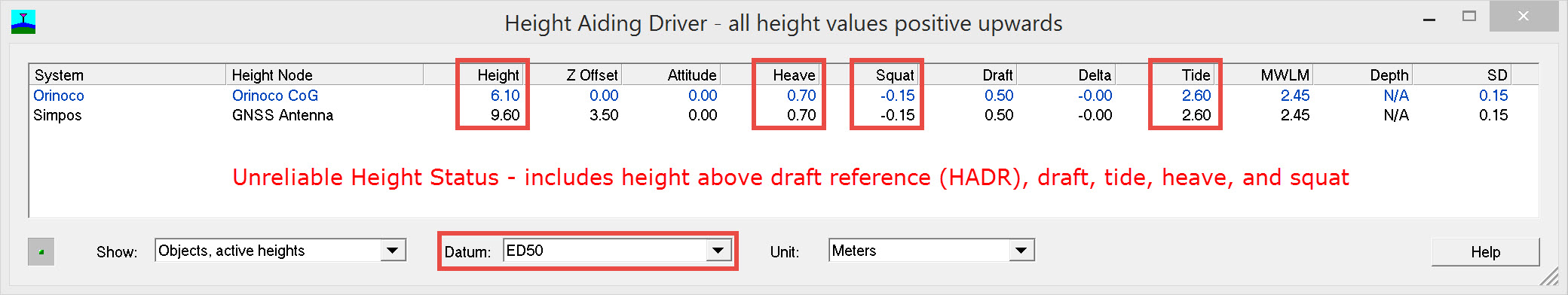
Now the vessel CoG height computed with 'unreliable' height status is +6.10, the same as for the 'accurate' height status scenario.
The 'Delta Height' vale of 3.65 is derived as follows:
Delta Height = HADR - Draft + Tide + Heave - Squat
Delta Height = (+2.20) - (+1.70) + (+2.60) + (+0.70) - (+0.15) = +3.65
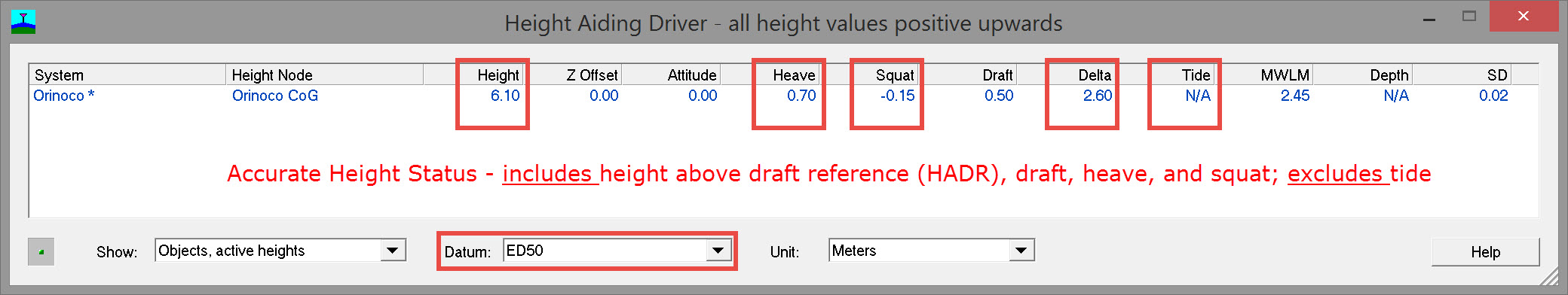
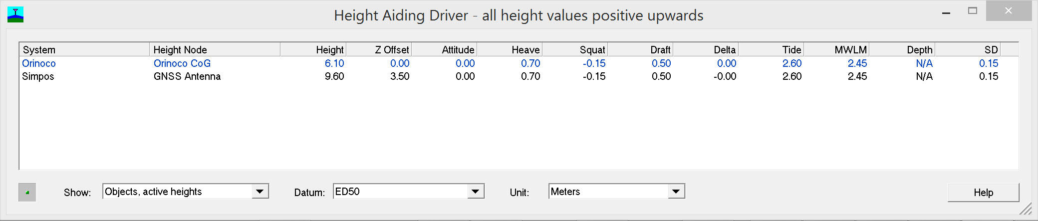
Delta height usually corresponds to a water level correction, i.e. an unknown tide value and/or an inaccurate geoid model height, but it also includes offset errors, attitude errors, ROV depth errors, and/or datum shift errors. The delta height value can be used to determine a tide value from RTK heights. In our example a Delta Height of +2.60 represents a tide value (image below).
Re-enabling all height aiding observation components except tide, the Height Aiding Driver window looks like this:
Vertical position of a vessel and towed fish on the water level - 3D
Delta Height of Vessel CoG and Fish CoG
In the example scenario used above, the CoG accurate height is 6.10 and the Fish CoG is -0.20; no height offsets like tide, draft and height above draft reference are applied in computing this value.
The Height Aiding dialog window for this particular scenario shows a 'Delta Height' value of 3.65 for the vessel CoG and for the fish CoG. How are these numbers derived?
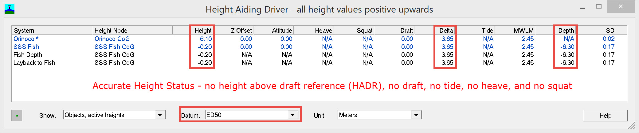
Delta height = 3.65
If height status is switched from 'Accurate' to 'Unreliable' and no other changes are made, the height aiding dialog window contains the following values:
Now the vessel CoG height is +2.45, and the Fish CoG is -3.85
So the Accurate Height minus Unreliable Height is
(+6.10) - (+2.45) = +3.65 (vessel)
(-0.20) - (-3.85) = +3.65 (fish)
The shift in height for the CoG is
(+6.10) - (+2.45) = +3.65
which equals the Delta height value shown in the 'accurate' case.
With an 'unreliable' height status and with the usual height aiding components, HADR, draft, tide, heave and squat enabled, the Height Aiding Driver window contains the following values:
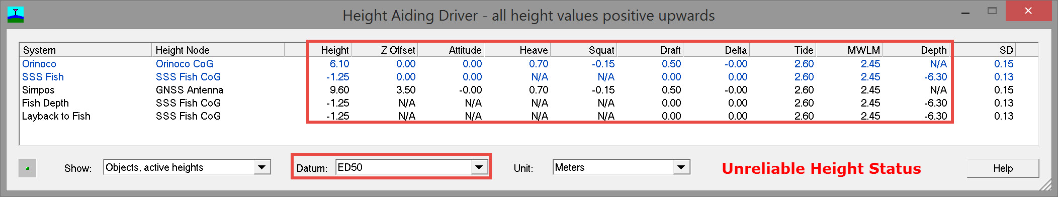
Now the vessel CoG height computed with 'unreliable' height status is +6.10, the same as for the 'accurate' height status scenario.
The 'Delta Height' value of 3.65 is the sum of height aiding components as follows:
Delta Height = HADR - Draft + Tide + Heave - Squat
Delta Height = (+2.20) - (+1.70) + (+2.60) + (+0.70) - (+0.15) = +3.65
Limitations to applying Delta Height
Water level correction (delta height in the Height Aiding dialog box) is only applied to height aiding nodes if:
- A Height node is enabled in a computation with one or more enabled accurate heights on 'above water' objects.
- A Height node is enabled in a computation in which another height node with a water level correction is enabled.
The only object types that are now used to determine the actual water level are vessel objects and towed buoys.
Water level corrections are calculated by comparing accurate heights with heights computed from object settings.
To prevent an external height observation causing a shift in heights through water level corrections:
- Add new positioning systems with accurate height setting to new computations.
- Add new positioning systems to existing computations using unreliable heights.
Be aware that one height node (unreliable height) will get the same height value across multiple computations.
Note
External vessel objects such as tugs should be added to new computations if they have accurate heights.
Accurate and unreliable objects can be compared (only) if there are no across-computation height nodes.
Settings
View which settings should be used for 3D positioning in the Height 3D -RTK- Settings document..
Return to top of page.
2D Positioning / Unreliable Height (Tide)
Unlike 3D positioning, in 2D positioning the height measurement component is not used in the height calculation.
Point positioning GNSS or Differential GNSS, for example, are systems providing heights that are neither accurate nor stable enough to be used within the height calculation when accurate seabed soundings (for example) are needed.
The latitude and longitude provide the horizontal positioning (2D positioning), but the height of the vessel needs to be calculated from other sources.
These height sources are:
Height Aiding Observation Components
Mean water level model
This is a geoid model, plus optional river line model, plus optional height offset, used in Qinsy to reduce tide observations to.
The actual raw tide observations can be referenced to another level such as LAT or any other local reference level, so it is important that for each fixed node connected to a tide observation, the Vertical Datum is set to the proper tide station reference level.
'Geoid separation' is the height of geoid (MWLM) above ellipsoid. It is not the height difference between MWLM and 'Chart Datum / Vertical Datum' as in DbSetup or 'Chart Datum' in general.
'Height reduction' in Database Setup is the difference between MWLM and vertical datum.
For height reduction there are the options: Mean Low Low Water Spring Northsea and Lowest Astronomical Tide for the Northsea.
Also a user defined River Lines model can be used.
Chart Datum / Vertical Datum
All the published footprints are calculated relative to this datum, which could be ITRF, local datum or Mean Water Level Model. Depth values in nautical charts are relative to this vertical datum, commonly known as 'chart datum'.
Height above draft reference (HADR)
This is the height of the CoG above the draft reference. The height above draft reference is a fixed value. The draft reference is the common level from which the draft of the vessel is measured.
This could be the bottom of the transducer, the bottom of the keel, or the top of the deck for instance. It might even be a mark on the pole of an over-the-side mount.
Draft
This is the vertical distance between the waterline and the bottom of the draft reference. This value changes over time due to different payloads. Only a vessel can have a draft, transducers of echosounder systems don't have draft in Qinsy.
Change of Draft
When the draft changes, make sure this value is updated in the Online - Settings - Computation Setup - Vessel setup - Draft and Squat Parameters.
Tide
Tide is the height of the water level with respect to a height reference surface close to the geoid, e.g. LAT.
Squat
Hydrodynamic phenomenon where the vessel may slightly pitch or sink due to an increase in speed. Most noticeable in shallow water. The CoG point moves downward by the squat amount. The effective draft is increased by the squat amount.
Heave
Vertical movement of the vessel due to waves and swell.
2D Positioning Height Computation
When using 2D positioning these individual height sources are shown in the Height Aiding Driver dialog. This driver uses the individual height sources in combination to compute the so-called Height Aiding Observation which replaces the measured height in 3D positioning. The driver is automatically started when the Qinsy Controller is started.
The 2D positioning method can be divided into three segments:
Resulting water level
Tide Reduction
Because the height of the GNSS is not used, a different height level or height reference is needed, as indicated above. For 2D positioning Qinsy makes use of a "Mean Water Level Model" as height reference. CoG is assumed to lie at the water line with an assumed height of zero.
This means that all the depths that are measured should be relative to the waterline.
The instantaneous actual water level is a combination of tide, referenced to some vertical datum, and heave. The tide vertical datum may be LAT or any other local reference level.
Actual water level must be reduced to the Mean Water Level reference plane. Heave is not not shown in the diagram below but would be a higher frequency time series imposed on the tide time series.
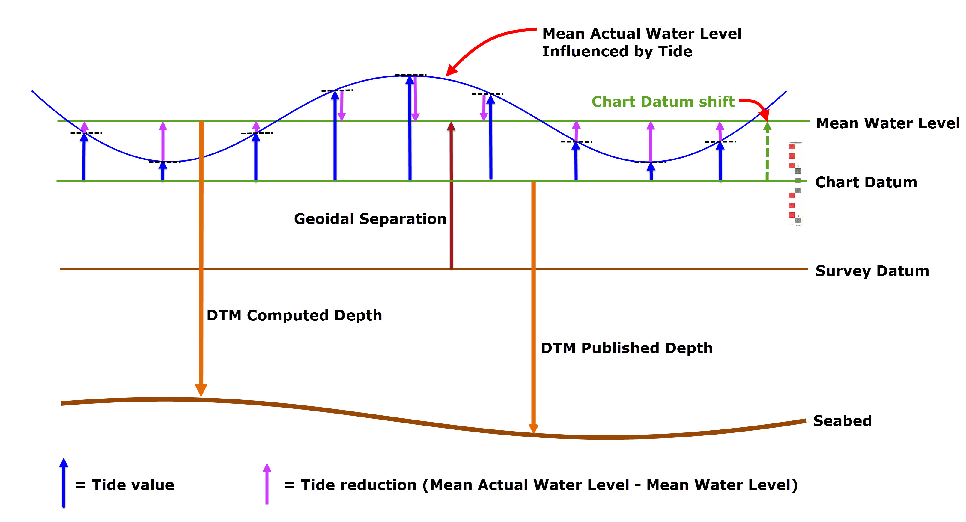
Mean Actual Water Level = Actual Water Level - Heave
Mean Water Level = Actual Water Level - Tide - Heave
Mean Water Level is most often represented by a Mean Water Level Model.
Tide is a temporary height correction to the "Mean Water Level Model" because the tide value changes with time. When the tide value for a certain time is known, the measured depths can be reduced to the "Mean Water Level Model".
The tidal variations that are measured by the tide stations are all relative to some vertical datum which may, or may not, be MWLM. Tide gauges are sometimes referenced to other datums such as LAT, MLLW etc..
In Qinsy 'Tide reduction' is the difference between Mean Actual Water Level and Mean Water Level.
Therefore, in order to reduce tide correctly, it is important to know which vertical datum tide values are referenced to, and, if that vertical datum does not correspond to MWLM, it is necessary to know the 'chart datum shift' from MWLM so that a relative correction may be applied.
Chart datum shift may be a constant offset from the MWLM, or it may vary across a geographical area. In the latter case a grid of chart datum shifts allows interpolation of the shift pertinent to the vessel position.
In the diagram above we want to reduce tides to Mean Water Level but measured tides are referenced to a different chart/vertical datum. Account for this chart datum shift must be made when defining the tide station, as in the image below.
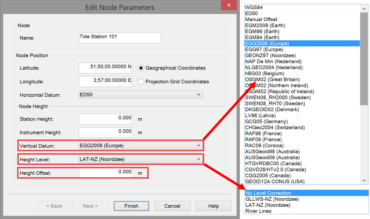
As with the Mean Water Level Model and the Vertical Datum / Chart Datum definitions, the tide station node definition also consists of three parts:
- an absolute geoid model. Geoid separation is the height of the geoid (MWLM) above the ellipsoid (survey datum).
- a relative height correction model, e.g. river lines.
- and/or a manual height offset.
If a tide station outputs water level relative to LAT, then the LAT model should be selected as Vertical Datum for the fixed tide station node connected to the tide observation.
If a tide station outputs the water level relative to a local datum, then this local datum must be selected as Vertical Datum for the tide station node connected to the observation.
In the example EGG2008 (Europe) is selected as the Vertical datum, and the relative height correction model is LAT-NZ (Noordzee).
Geoid separation is always calculated for any MWLM or Chart Datum not being the survey datum ellipsoid.
Chart/Vertical Datum
In some cases the Chart/Vertical Datum reference for publishing of depths to the chart is not the "Mean Water Level Model", but a different ellipsoid or geoid. In that case the alternative Chart/Vertical Datum must be set on Page 3 of the Geodetic wizard in Database Setup. When the vertical output datum is different from the "Mean Water Level Model" a geoid separation is calculated. A geoid separation is the vertical difference between two geoids for a specific location. The measured depths in the chart will not be relative to the "Mean Water Level Model" anymore, but relative to the Chart/Vertical Datum that is used in the chart.
It is common to apply a tidal correction afterwards in post-processing instead of applying tide corrections during the survey.
Example
For a certain survey the tide was measured referenced to a local datum, for instance NAP (local Dutch geoid). The "Mean Water Level Model" in Qinsy would be set to NAP. But the charts that are produced must be relative to LAT. The height difference between NAP and LAT must be applied to correct measured depths in the chart so that they will be relative to LAT. By selecting LAT as Chart/Vertical Datum Qinsy will apply the geoid separation.
Example
For river surveys it is common to use a river line model as "Mean Water Level Model". A river line model is a height model that suits the local conditions the best. For example: when the start of a survey area is at an altitude of 200 meters and the end is at sea level you want the depths to be relative to a model that takes the drop of the river into account. For instance, the measured height of the bottom is 205.40 meters but the river is only 5.40 meters deep. The depth that will be stored in the chart will be 5.40 meters.
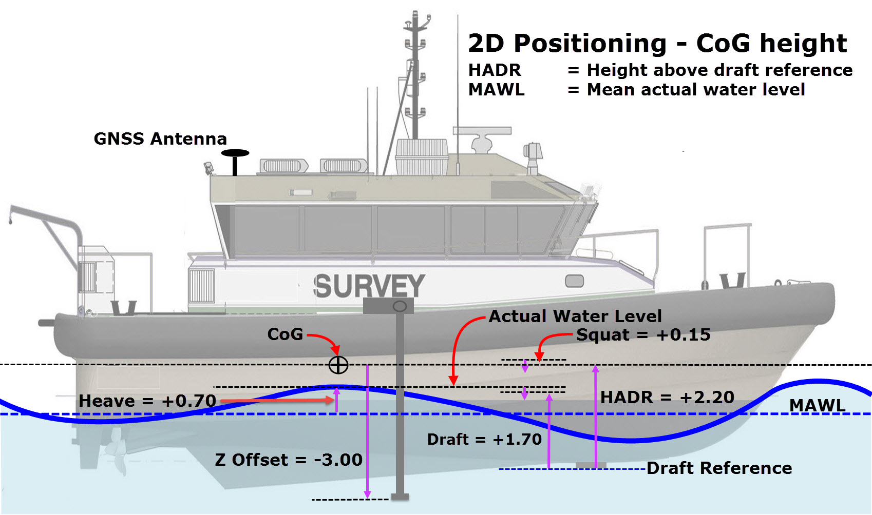
Vertical position of the vessel on the water level
With 2D positioning the depths are expressed relative to the water line; therefore it is important to know how the vessel is positioned relative to the water line.
The way Qinsy works is that all depths that are measured are relative to the height of the CoG. This works fine as long as the CoG is lying exactly on the water line. Of course this is never the case, and therefore the vertical distance between the CoG and water line needs to be determined in order to correct the measured depths to the water line.
The first thing that should be done is to determine a draft reference plane. Often the bottom of the keel is used.
To determine the vertical distance between the CoG and the water line, two measurements are needed
- the height of the CoG above draft reference (HADR) and
- the draft which must be measured or determined in some way.
The HADR can be calculated from the offset measurements, and the draft can be measured with a bar-check or by checking the draft marks on the hull of the vessel. Alternatively a draft or depth sensor may be used.
As long as the HADR and the draft are set to "0" Qinsy will assume that the height of the CoG is equal to the waterline. When the HADR and draft are entered correctly into Qinsy, the height of the CoG in Qinsy relative to the water line is the same as when this distance is measured with a tape measure for instance.
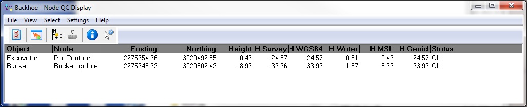
The best way to check if the height of the CoG relative to the water line is correct, is to display the height of the vessel's CoG in a Node QC display.
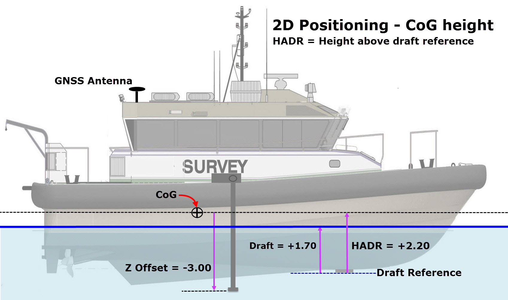
Example
A survey vessel has the following HADR and draft values:
HADR: 2.20 meter
Draft: 1.70 meter
This results in a height of the CoG of 0.50 meter above the water line, this will also be displayed as 0.50 meter in the Node QC display. All node offsets will be affected by this height change, and all transducer offsets on board the vessel will show the correct depth below the water line.
Dynamic influences
Qinsy now knows how the vessel is positioned on the water as it floats in calm water. But due to influence of waves and swell the vessel is constantly moving up and down. This is called heave. This vertical movement needs to be corrected in order for Qinsy to compute the correct depth value. The heave values are applied to the CoG height and thus all the variable nodes on the vessel will be corrected for heave.
Qinsy needs the heave value at the CoG (i.e. the reference point for rotations). Therefore, it is important to note that pitch-roll induced heave must be left out of the (height) equation. Either the MRU (pitch-roll-heave sensor) must output heave for the vessel reference point, or the heave filter length must be set properly, so that Qinsy can correct for the lever arm of the heave observations.
When the vessel is in motion the vessel is also subjected to squat. Squat is a phenomenon whereby the vessel will pitch or slightly sink into the water when it is moving through the water. This value is a variable number that changes with the speed of the vessel through the water. In addition to speed, the shape of the hull and the water depth are also factors that influence squat. Squat is difficult to determine and/or to measure, therefore this is often used as an optional setting.
As with the heave, squat's vertical influence must be used to correct the height of the CoG in order store the correct depth values.
Vertical position of a vessel and towed fish on the water level - 2D
Settings
View which settings should be used for 3D positioning in the Height 2D -Tide- Settings document..
Height and related settings can be checked in various displays:
Use the Node QC Display:
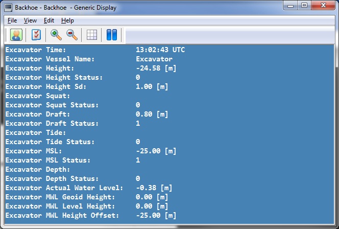
The Generic Display:
The Profile Display:
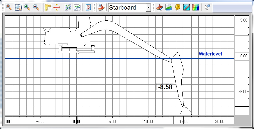
Height Aiding Driver
The Height Aiding Driver computes a Height Aiding Observation, which is used when the height component of position is too inaccurate and/or too unreliable for the survey task.
Typically the Height Aiding Observation is required when GNSS receivers are used in point positioning or differential mode.
The Height Aiding Driver Display is launched automatically when the Controller is started.
Minimizing the window is recommended unless the height aiding components need to be checked.
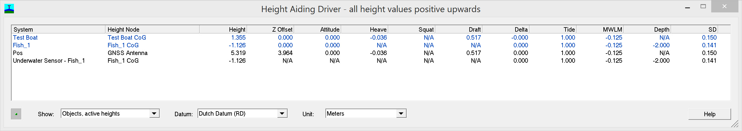
All the height component values are positive upwards, which means that positive bathy depths are displayed as negative heights.
'N/A' means either 'Not Applicable' or 'Not Available'.
Column | Description |
|---|---|
System | System name in case of height aiding observations (black text) and Object name in case of object heights (blue text). |
Height Node | ‘Height Node’ is just a short description for ‘height aiding observation at object node’. Height aiding observations are computed by the Height Aiding Driver for positioning systems and satellite systems that have unreliable heights, for bathy depth and pressure observations, and for the ‘to node’ with manual layback observations. |
Height | Height above Survey Datum, or height above WGS84 Datum in case raw GNSS data are interfaced. |
Z Offset | Offset of the node relative to the CoG, for example the node offset of a GNSS antenna or bathy sensor. |
Attitude | Correction to Z offset to account for pitch and roll according to object attitude priority. |
Heave | Heave component according to object height priority. |
Squat | Squat component according to object height settings. |
Draft | Draft component according to object height settings. |
Delta | ‘Delta Height’ is the height difference between an accurate height (e.g. from RTK) and an unreliable height (computed using database settings such as the mean water level model and object height settings as defined in the Computation Setup). |
Tide | Tide height according to object height settings. |
MWLM | Mean Water Level Model height according to geodetic database settings. In case only a geoid model is selected in the database, this corresponds to Mean Sea Level height. |
Depth | Bathy depth (or converted pressure) according to computation settings. |
SD | Standard deviation (1-sigma) computed from object settings and observation SD's. |
The object heights are computed for the object reference node in order to transfer height differences between objects and computations and in order to transfer object height components to other Qinsy modules.
The delta height has been implemented in order to be able to combine accurate RTK heights on vessels with bathy depths on towed fish objects, in case accurate tide values (or geoid heights) are not available.
More information on the various height component settings can be found in the Help pages of the Database Setup program (Geodetic Parameters, Object Definition), the Controller's Computation Setup and the Height Aiding Driver window.
Option | Description |
|---|---|
Show: | Select type of information to show. In release mode, three options are available: |
Datum: | Select datum for heights. Currently only the computation datum is available. |
Unit: | Select unit for height values. Currently only the survey unit is available. |
Return to top of page.
Height Aiding Practical Example
Using the Qinsy position and motion simulator, the following example illustrates the principles explained above. The known position of the GNSS antenna is:
| Datum | Latitude | Longitude | Height (m) |
|---|---|---|---|
| ETRS89 | 51 54' 04.99" N | 4 22' 50.35" E | 41.35 |
| Amersfoort / RD New | 51 54' 08.43" N | 4 22' 51.39" E | -2.40 |
| NAP + Height offset | -2.26 |
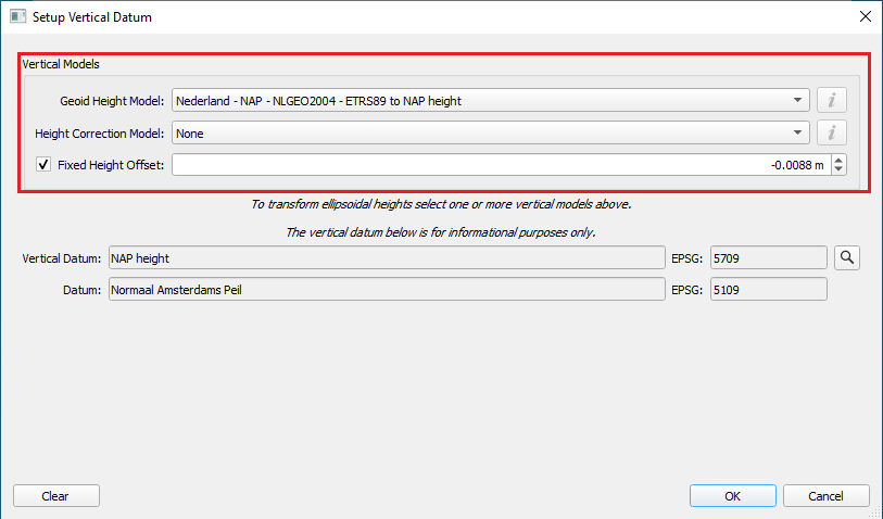
Mean water level model = NAP height
Fixed Height offset = -0.0088 m
Please refer to
- The Height 2D -Tide- Settings mode document
- The Height 3D -RTK- Settings mode document
for diagrams and online displays for this example.
Info
For offshore operations the heights from a GNSS receiver can be quite accurate, but still have some noise and sometimes even an incorrect height (spike).
The solution is filtering the height and presenting this as a pseudo tide.
To use the RTK Tide for height aiding, please refer to the following document: How-to RTK Height as Tide.
Return to top of page.