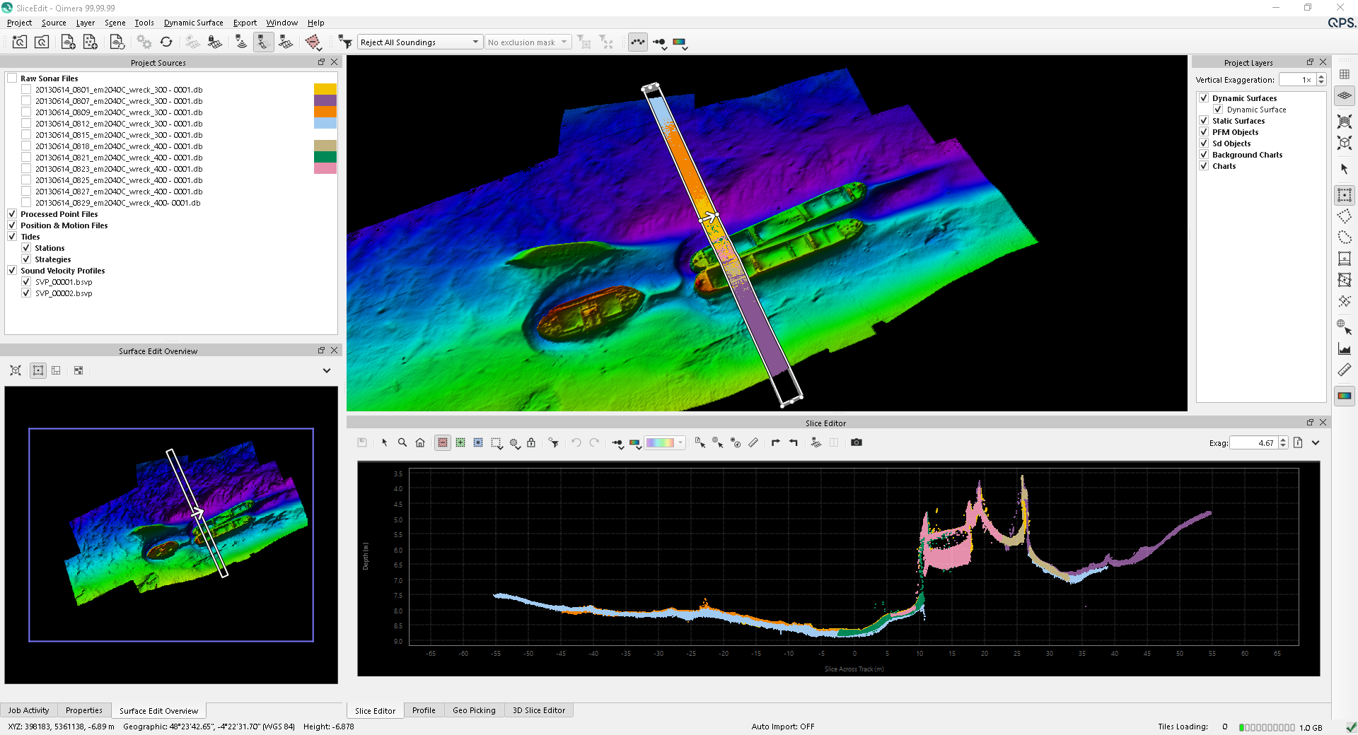
The Slice Editor allows you to edit the soundings of your surface in a 2D projected widget. The Slice Editor uses any of the area selection modes but is primarily used with the Fixed Slice Select or Free Slice Select. Use of these modes is described in detail in section 4D Scene Toolbar.
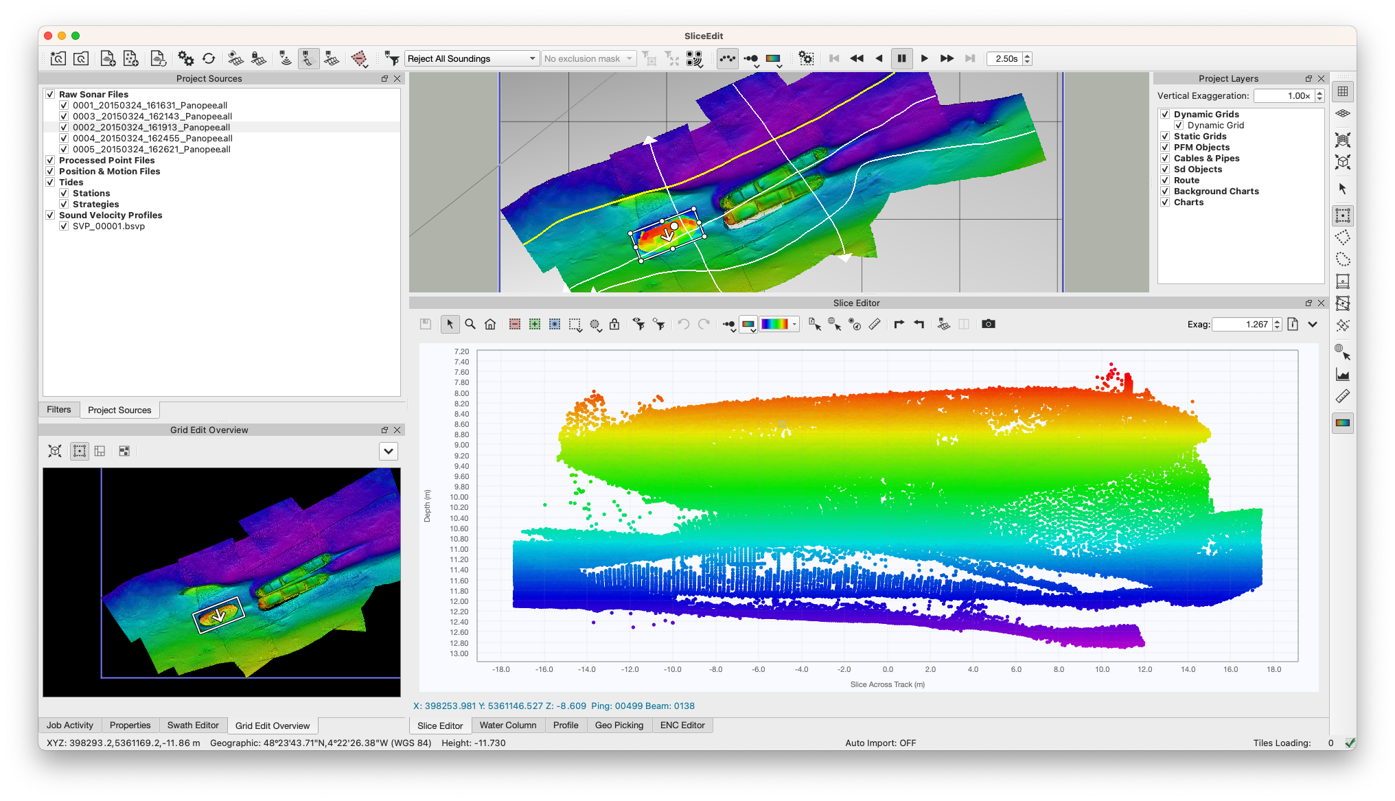
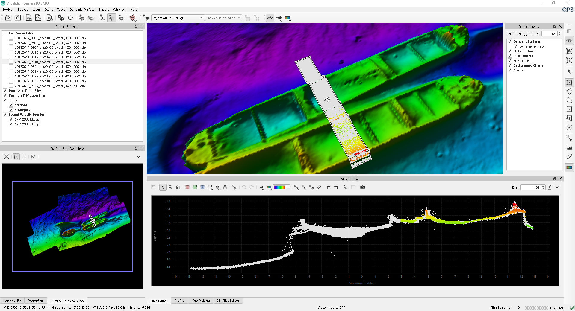
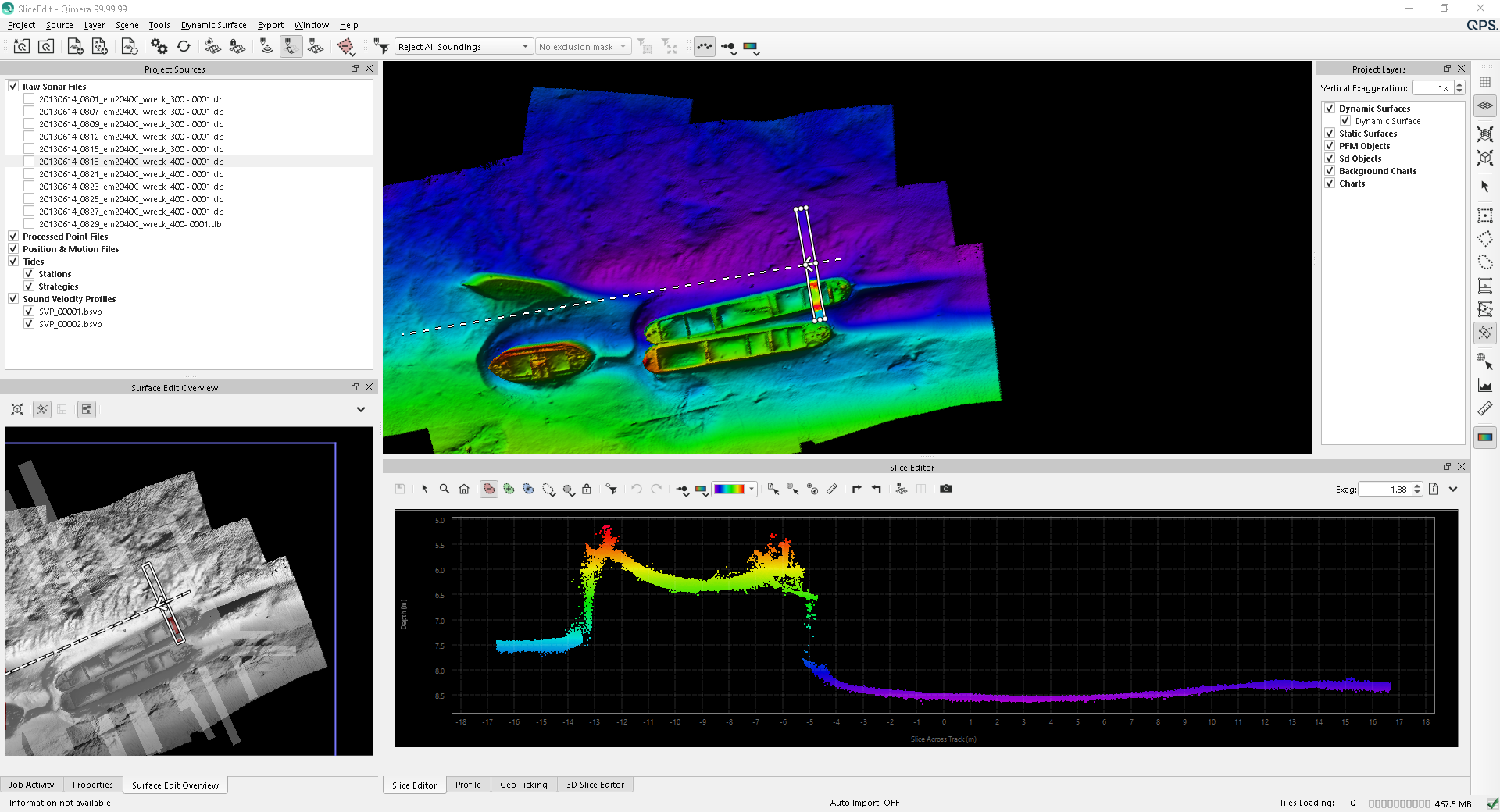
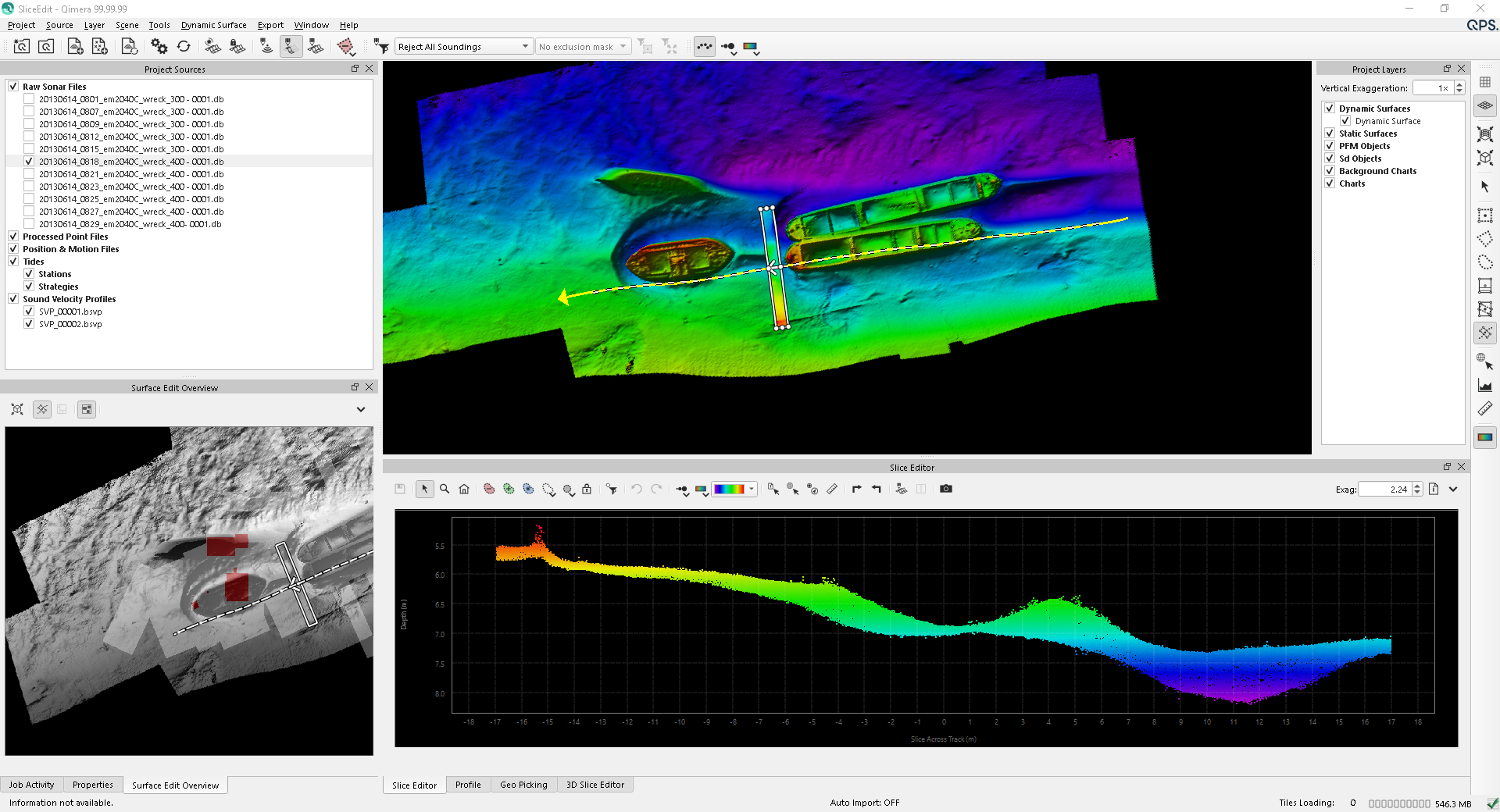
To start slice editing, simply click the button from the Bathymetry Toolbar. The 2 key is also the default hot key for this mode. This will create a default Fixed Slice selection in the middle of your Dynamic Surface. You can also create your own area selection to start. Slice editing works in either a Manual Area, GuidedArea or Linked Area editing mode. All of these modes are described in detail below. If you are using Rectangle, Freehand, or Polygon selection mode, Qimera will load all of the soundings that fall within the selection in to the Slice Editor. If you are using Fixed Slice or Free Slice, Qimera will load only the soundings within the slice portion of the selection into the Slice Editor. The 4D Scene will show all of the soundings within the Overview area portion of a slice selection, or main selection if using any other selection mode. An example of this using the Fixed Slice selection is shown below.
The Slice Editor works in tandem with the 4D Scene and the Surface Editor Overview. See the specific sections on these windows for additional information. The key is that you can change the selection in either the 4D Scene or the Surface Edit Overview. The Surface Edit Overview allows you to maintain an awareness of your current edit area with respect to your entire survey. The Surface Edit Overview also allows you to see the progress of your editing and display a partitioned grid that allows you to systematically edit your surface. See the section on Guided Editing below for information on using a partition overlay.
For information on plot surface navigation and editing, see the page in the manual on Qimera Plotting Surfaces.
Remember that when the 4D Scene is in a selection mode, simply hold down the SHIFT key while using the mouse to perform normal navigation in the scene. If you are using the Navigate By Default from the Preferences Dialog, you need to hold down the SHIFT key to make a new selection.
Slice Editor Toolbar
Save Edits
This button will save any edits that have been completed.
Explore
This button places the window in Explore mode. As you move your cursor over the plot area, you will see a corresponding highlighted (white) sounding in the 4D Scene. Depending on what your Color By option is set to, you will see the position, ping, beam and Color By attribute value in the Cursor Info section of the widget. If the project has an active route, the KP and DX coordinates will be shown as well. See the section on Plotting Surfaces for more information on plot surface navigation and control.
Zoom In
This button places the cursor in Zoom mode. Please see the section on Plotting Surfaces for more information on plot surface navigation and control.
Reset Zoom
This button zooms out the plot window to the extents of the data. Please see the section on Plotting Surfaces for more information on plot surface navigation and control.
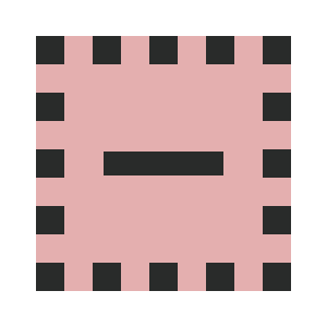
Reject Selection
This button places the cursor in Reject Selection mode. Holding down the CTRL key will invert the mode between Reject and Accept. Use the selection style and selection area drop down buttons to modify the selection style.
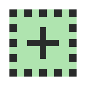
Accept Selection
This button places the cursor in Accept Selection mode. Holding down the CTRL key will invert the mode between Reject and Accept. Use the selection style and selection area drop down buttons to modify the selection style.
Select and Edit
This button places the cursor in Select and Edit mode. Select and Edit mode allows you to select (or deselect) soundings in the slice view using the difference selection tools. Once you have the desired soundings selected, right-click on the plot surface to bring up the Slice Editor Context Menu to execute an action on the selected soundings. Holding down the CTRL key will invert the mode between select or deselect.
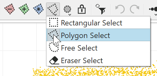
Selection Style
This button changes the selection style of both the Reject and Accept buttons. Clicking this will rotate through each of the styles, or long pressing will give you a drop down menu to select the style.
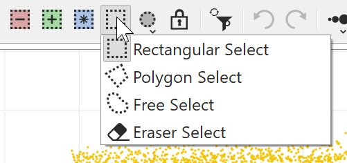
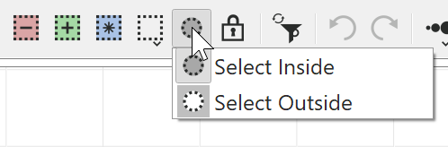
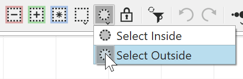
Selection Area
This button changes the selection area of both the Reject and Accept buttons. Clicking this will rotate through each of the areas, or long pressing will give you a drop down menu to select the area.
Lock Selection
This button will enable or disable selection locking, which can be used to automatically edit soundings that fall within the plot selection. Reject or AcceptSelection mode enables this option and makes a selection, the selection will remain and Reject or Accept footprints as you move the slice through the scene. To clear the selection either disable this option or switch to explore.
See the section on Plot Surface Editing for more information about editing with these tools.
Run Filter Preview
This button activates the Filter Preview feature, applying the active filter profile on the chosen data subset without causing permanent changes. This facilitates the visualization of the active filter's effects on a specific set of points before applying it to either the current selection or the complete dataset using one of the various filter application features. The current filter profile can be viewed and modified in the Qimera Filter Profile Dock and the Filter Operation Toolbar. Any modifications made to the active filter profile will be immediately reflected in the filter preview. The filtered points will be easily distinguishable and color-coded, following the user-defined preferences found in the Qimera Preferences under the plotting colours section.
Run Filter Profile
This button will run the active filter profile on the data within the slice. For more information on managing, selecting and running filter profiles, see the Filter Operation Toolbar. Executing Filter Profiles in the Slice Editor obeys the same option configuration as standard editing. For example, if you are in Save Edits Instantly mode, the soundings that are rejected or accepted by the filter will be immediately saved back to the QPDs and the surface will be updated. If you have the Edit Only Selected option, the filter profile will run only on the selected lines in the slice.
Undo
This will undo the last operation. The undo buffer is pseudo-infinite and limited only by memory. So it will undo each edit in sequence. The Undo buffer clears when you move your selection.
Redo
This will redo the last undo operation. The undo buffer is pseudo-infinite and limited only by memory. So it will redo each undo edit in sequence. The Redo buffer clears when you move your selection.
Plot Point Size
Clicking the first of these icons will change the point and line size drawn in the slice views of the widget. If you click and hold the button, it will display a menu where you can select point sizes between Small and XX-Large. Simply clicking will cycle through all sizes.
Plot Color By
Clicking the first of these icons will change the Color By mode of the points drawn in the widget. If you click and hold the button, it will display a menu where you can select the Color By option directly. The options for Color By are Vessel (shows default port/stbd color), File, System, Ping, Beam, Selection Depth (scaled to depth range of the pings in the plot), Surface Color Map (depths colored by the color map of the currently selected Dynamic Surface), Intensity, Horizontal TPU, Vertical TPU and Solid Color. For LAS/LAZ files, there are also color by options for RGB and Classification. When Color By File is used, you will additionally see the matching colors appear next to the line name in the Project Sources Dockas show below. When Color By Solid Color is used, the Colormap Settings will be replaced by the Color Button.
Colormap Settings
This will allow you to select and adjust a colormap for the points drawn in the widget. This allows for the same controls as users would have over the coloration of a Dynamic Surface: selecting a colormap, adjusting the range and editing a colormap. Some settings for Plot Color By do not allow access to a colormap, e.g. color by Vessel, File, System, Ping, Beam and Surface Colormap.
Color Button.
This will allow you to select a color for the points drawn in the widget. The color button is used for selecting a color for Color By Solid Color.
Select Info
This button places the cursor into Select Info selection mode. When you click on a sounding in the plot window, it is highlighted as a white sphere in the scene. It will persist until you either change your selection or pick a new sounding. This way you can correlate what you see in the plot window to what you see in the 4D Scene. If you have the Sounding Properties window open, it will also fill in information about the sounding.
Geo Pick
This button places the cursor into a Geo-Pick selection mode. When you click on a sounding in the plot window, a position entry is added to the Qimera Geo Pick Dock.
Add ENC Point Object
This button places the cursor in ENC Point Creation mode. Each time you click a sounding in the view, the Create ENC Object dialog will raise. To learn more about creating ENC objects, see the section on the Qimera ENC Editor Dock. Creating ENC point objects from soundings results in the VALSOU attribute of the feature being automatically assigned to the processed depth of the sounding.
Measure
This button places the cursor into measure mode. Using a right-click and drag, you see the Z Delta, X Delta and Range. This measurement is in plot coordinates.
Rotate Right
This button will immediately rotate the Overview part of the Fixed Slice and Rectangular Selection 90 degrees to the right. It will also rotate the Slice part of the Free Slice Selection 90 degrees to the right.
Rotate Left
This button will immediately rotate the Overview part of the Fixed Slice and Rectangular Selection 90 degrees to the left. It will also rotate the Slice part of the Free Slice Selection 90 degrees to the left.
3D Slice
This button will launch the embedded 3D Slice Editor, allowing for editing in Slice mode and 3D mode at the same time.
3D Slice Layout
The 3D Slice Layout button allows for control of how the 2D Slice and the 3D Slice plots are drawn. The different options are:
Horizontal Split 2D/3D Slice: 2D and 3D slice editors share the same dock and are placed next to each other horizontally
Vertical Split 2D/3D Slice: 2D and 3D slice editors share the same dock and are stacked vertically
Docked 3D Slice: 3D Slice is drawn in a separate dock, which can be placed any where in the application, or floated independently of the 2D dock
Snapshot
This button will save a Point SD object for the currently selected soundings in the scene and will appear under the SD Objects tree on the Project Layers widget. You have to be in Selection and Edit mode and have some soundings selected to use this feature. The snapshot SD will get the name 'Slice_Snapshot_#####'. If you wish to use a specific name for the snapshot, use the Slice Editor Menu option Save Snapshot or hold down the CTRL key while you click the button. This will bring up a Save File dialog that will allow you to name the object. Snapshots are meant to be used as simple visual mark up cues in the working area to give you a method to easily keep track of items that you have reviewed, or to perhaps capture objects of interest that require further examination or analysis. You can use these objects as "bookmarks" in your data. To quickly navigate to their location, select them in the SD Objects tree and click the Z key or use the Zoom to Object button of the 4D Toolbar.
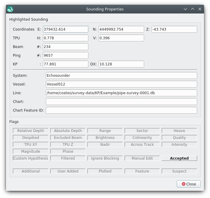
Show Sounding Properties
This button will display the Sounding Properties Dialog shown below. As you move your cursor over the soundings in the plot view, the information in the dialog will update accordingly. The top 2 sections of the dialog should be self explanatory. The Flags Section shows the detailed information about the QPD status flags for each sounding. If the button is bold and raised, the flag is set.
Head Visibility
With multi head data, Qimera will allow you to individually turn heads on or off during Slice Editing. The tool tip for each button will display the name of the head assigned to the button. You will only see these buttons when you have more than 1 head in your data.
Slice Editor Menu
Auto Load Points
By default, when you change the selection location in the scene, the underlying points are automatically loaded to the slice editor. If you are working on large, dense data sets and like to refine your selection first, simply un-check this option and use the ENTER key to load points to the slice editor. When you first start slice editor, it will do a normal auto load, but as you move your selection, it will not load points until after you hit the ENTER key. You can change this hotkey using the Hot Key Configuration panel accessed by the File Menu.
Edit Only Selected Files
This option allows you to edit specific lines that appear in your slice. You can select multiple lines from your Project Sources tree or you can right-click on a sounding and use the context menu to select the line the sounding belongs to. Lines that are not selected are drawn with a very light gray as shown in the example below. The soundings from the selected lines will always be drawn on top of the unselected lines in the plot view.
Show Unselected Files
This option allows you to show/hide unselected files when you are in the Edit Only Selected Files mode. This can greatly reduce the clutter when editing dense data.
Save Edits Manually
This option requires that you click on the Save button to save edits to your QPDs. After saving, any Dynamic Surface with Update Mode set to Always will immediately update. If you move your selection, you will be prompted to save any unsaved edits.
Save Edits Automatically
This option automatically saves edits when you exit the Slice Editing session or move your selection area. After saving, any Dynamic Surfaces with Update Mode set to Always will immediately update.
Save Edits Instantly
This option instantly saves edits when you reject or accept a sounding. After saving, any Dynamic Surface with Update Mode set to Always will immediately update.
Update Illumination
This option will ask Qimera to recompute illumination on the minimum bounding rectangle of your entire selection after re-gridding from saved edits. This is useful when you have "Cast Shadows" on for your Dynamic Surface. When you save edits in the Slice Editor, the grid only updates in the area of your edits. If you have shadows, your shadows may not be updated. You can use this option, along with an encompassing selection, to ensure that shadows are updated from your edits.
Automatically Apply Active Filter
This option will automatically run the currently active filter whenever the slice selection is moved. This mode is especially useful for "spike hunting". Where you choose an appropriate spline filter, and select an appropriate area with a spike on the surface. Choose the Save mode of your choice from the above options. Finally, ALT-Left-Click a new location containing a spike on the surface to automatically apply the filter to the new location.
Auto Set Flag on Select
This option will automatically set a specific bit flag when you make a selection of soundings. This option only works during the Select and Edit mode. You can automatically set the Suspect, Plotted or Feature flag. Decide which flags you want to select then using one of the selection modes, start selecting soundings. You can verify by clearing the selection and using the Right-Click context menu to Select By the flag of interest.
Auto Zoom
This option will cause the plot area to zoom to the extents of the visible soundings even while moving the slice in a selection. However, if you change the zoom using the zoom tool or the mouse wheel, you will stay in this zoom location. To allow Auto Zoom to work again, simply click on the Reset Zoom button.
Lock Vertical Exaggeration
This option locks the vertical exaggeration of the plot area while moving the slice selection.
Auto Track
This option will cause the 4D Scene to center on your current selection.
Show Scene Cursor Position
This option will show a white point in the 4D Scene and the Surface Edit Overview that correlates to the sounding that your cursor is over in the plot area.
Show Grid Lines
This option will turn grid lines on/off in plot area.
Show Soundings
Show Rejected
This option controls visibility of rejected points in both the Slice and 4D Scene. Rejected points could have been rejected by the sonar manufacturer, a blocking filter, or through a manual editing operation. Rejected soundings are dark or light gray. Light gray specify soundings rejected via blocking filters. Other system or manually edited rejected soundings are dark gray.
Show Filtered
This options controls visibility of filtered soundings in both the Slice Editor and 4D Scene. If Show Rejected is on, you can decide to separately show/hide soundings that were rejected by a blocking filter. These soundings show up as light gray.
Show Edited
This option controls visibility of soundings that have been manually edited by the user. Editing covers both cases where the user manually rejects or accepts soundings. Once a sounding receives the Edit flag, no filter or reprocessing operation will ever change the sounding's accepted or rejected state. The Edit (rejected) flag is also set for Additional soundings during raw sonar file import. Qimera pays attention to the specific sonar topside settings (i.e. class types for Kongsberg files) to determine which to reject. The Edit (rejected) flag is also set for any interpolated soundings found during raw sonar file import. Remember that the user can always perform a manual edit operation to un-reject any soundings marked by Qimera as Edit (rejected) during import. See the description below about Restoring soundings.
Show Normal
This options controls visibility of normal soundings. These are soundings that are neither interpolated or considered as additional.
Show Additional
This option controls visibility of additional soundings. Teledyne Reson calls these "multi detect" soundings while Kongsberg calls these "extra" soundings. For Reson, all additional soundings are automatically accepted during import and the user must remove those that are not desired. For Kongsberg, only the classes that have been configured as visible in SIS during acquisition are accepted at the import stage. The other classes (including class 8) are marked as rejected by Qimera upon import, however, they are still imported can be reclaimed by the user by viewing the rejected soundings and re-accepting the desired soundings
Show Profile
This option will control the visibility of the central depth profile from the grid across the long axis of the selection area that is currently active. The profile will drawn as an overlay in the Slice Editor itself and also in the Scene.
3D Options
A sub-menu contains several draw options for the 3D Slice.
All Grid - Enable/disable drawing of the background grid box entirely, including the grid, plane and coordinates
Grid - Enable/disable drawing of the background 3D grid mesh
Plane - Enable/disable drawing of the plane that is drawn underneath the point cloud
Coordinates Enable/disable drawing of the axis coordinate labels associated with the plane that is drawn underneath the point cloud
Show Surface - Enable/disable plotting of the Dynamic Surface within the 3D Slice
Smooth Points - Draw points as smooth points (spheres with a black outline) or as squares
Wireframe - Plot the Dynamic Surface as a wireframe
Shaded - Plot the Dynamic Surface as a Shaded Surface
Outline - Plot the Dynamic Surface as a Shaded Surface along with an outline of the grid cells
Save to Image
This option will save the plots to disk as separate filenames with the format
filename_Above.format or filrename_Behind.format or filename_Side.format
where format is your chosen image format (JPEG or PNG).
Save Snapshot
This does the same operation as the Snapshot button on the toolbar with the exception that you can explicitly name the SD file that is created.
Slice Editor Context Menu
The Slice Editor Context Menu is only available while in Manual Edit mode or when you have selected the Edit Only Selected mode. Options for this context menu are listed below.
Clear Selection
This option will clear the current selection.
Invert Selection
This option will invert the current selection.
Select Line
This option will select all soundings that match the line of the current sounding. The current sounding is the one under the cursor. When in Explore mode, you will see a red X appear over the sounding as you move your cursor around the plot.
Select System
This option will select all soundings that match the system of the current sounding. The current sounding is the one under the cursor. When in Explore mode, you will see a red X appear over the sounding as you move your cursor around the plot.
Select By
This option will select the soundings based on the desired flag or attribute. These are categorized in the table below.
Select By
Description
Shoalest
This will select a single sounding with the minimum depth in the current slice.
Deepest
This will select a single sounding with the maximum depth in the current slice.
Suspect
This will select all soundings with the Suspect flag set.
Plotted
This will select all soundings with the Plotted flag set.
Feature
This will select all soundings with the Feature flag set.
Additional
This will select all soundings with the Additional flag set. These are soundings generated by sonars returning more than one solution per beam.
Interpolated
This option is deprecated and will be removed in a future version of Qimera
Blocking Flags:
Relative Depth, Absolute Depth,
Range, Sector, Heave, Excluded (beam),
Brightness, Colinearity, Despiked,
Horizontal TPU, Vertical TPU,
Quality, Nadir, Across Track, Intensity
This will select all soundings with the selected flag set. For more information on these flags. Please the section on Blocking.
Filter
This will select all soundings with the Filter flag set. This flag is set when certain Filter Profiles are run. See the section on Filter Profiles for more information.
These include Line, System, Suspect, Plotted, Feature, Additional, Interpolated and the blocking/filtering flags for Relative Depth, Absolute Depth, Range, Sector, Heave, Excluded, Brightness, Colinearity, Despiked, Horizontal TPU, Vertical TPU, Quality, Nadir, Across Track, Intensity, Spline and Cube.
Reject
Reject the currently selected soundings.
Accept
Accept the currently selected soundings.
Set Suspect Flag
Set the Suspect flag for the currently selected soundings.
Clear Suspect Flag
Clear the Suspect flag for the currently selected soundings.
Set Plotted Flag
Clear the Plotted flag for the currently selected soundings.
Clear Plotted Flag
Clear the Plotted flag for the currently selected soundings.
Set Feature Flag
Set the Feature flag for the currently selected soundings.
Clear Feature Flag
Clear the Feature flag for the currently selected soundings.
Set selected points classification to the most recently used classification set in the Qimera Set LAS Classification dialog.
Manual Area Editing Mode
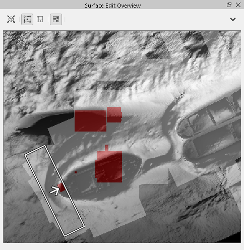
Manual Editing is the default state of the Slice Editor. You simply create a selection area on your Dynamic Surface using any of the area selection tools, do your editing, then move your selection to a new area on the surface. You can change your selection in either the 4D Scene or the Surface Edit Overview. If you have the Show Visited/Edited option enable for the Surface Edit Overview, you will be able to see which parts of the Dynamic Surface you have visited (loaded in the slice editor) and which areas you have edited. You can see an example of this below. The visited areas are a transparent white shape that matches the selection where as the edited areas are a transparent red rectangle based on the extents of the soundings you have updated.
Guided Area Editing Mode
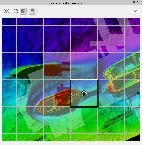
Guided editing mode allows you to do systematic review of your Dynamic Surface. You can use Fixed Slice, Free Slice, and RectangularSelection when using a Partition Grid. Be sure to read the section on the Free Slice, Fixed Slice and Rectangular selection modes in the section on the 4D Toolbar. Guided Editing ensures that you review the entire surface and limit the amount of soundings that are loaded to the Slice Editor in order to maintain responsiveness. Guided editing mode involves the use of a Partition Grid to organize your selections.See how to create a partition grid in the section on the Surface Edit Overview. An example of a grid partition used for guided editing is shown below. To load a new area, simply click in a tile of the partition grid or use one of the movement shortcut keys (W, S, A, D) along with the SHIFT modifier. The selection will automatically load the new tile area and you can move the slice through your data. As you move and edit, the Visited/Edited overlay is automatically updated.
Scroll Selection Editing
Scroll Selection Editing has replaced the previous Linked Editing mode. You use the Scroll Line Select mode to define a slice area and the line it will follow. See the section on the 4D Toolbar for more information on using this cursor mode. When you are in this mode, you can CTRL-click any existing line in the scene to attach your scroll line. You can move along the line by using the standard 4D Scene drag behavior of the rectangular selection, or, simply use the W and S hotkeys. When you are stopped, you can rotate the selection in any direction. When you stop, the soundings within the current selection will be loaded to the scene. The left image below shows a custom defined scroll line. The right image shows the scroll line defined via a CTRL-click on an existing track line in the scene.
Sounding Editing
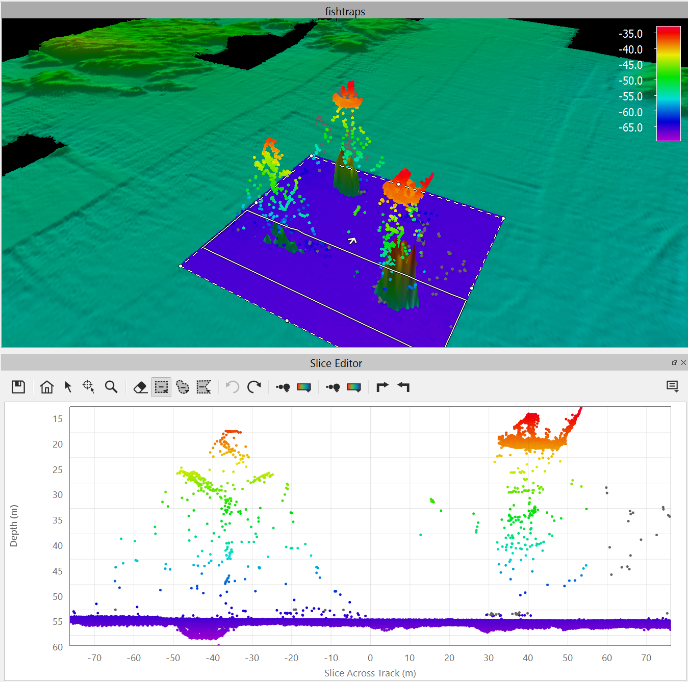
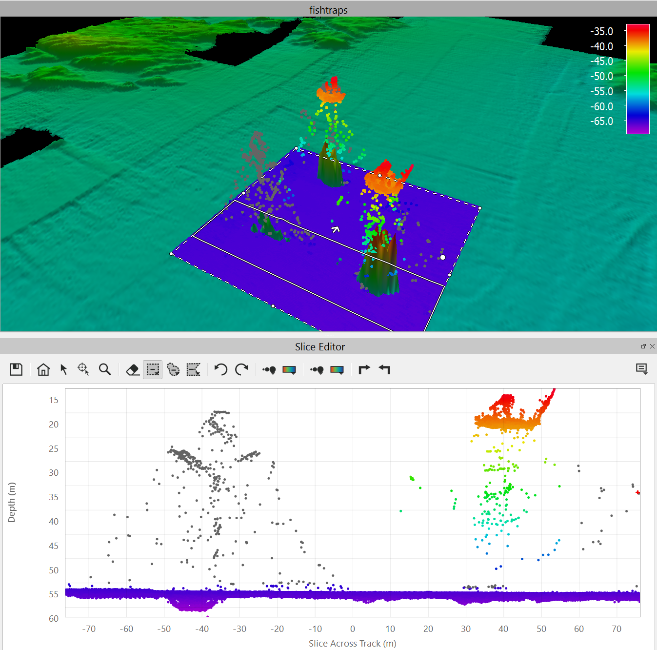
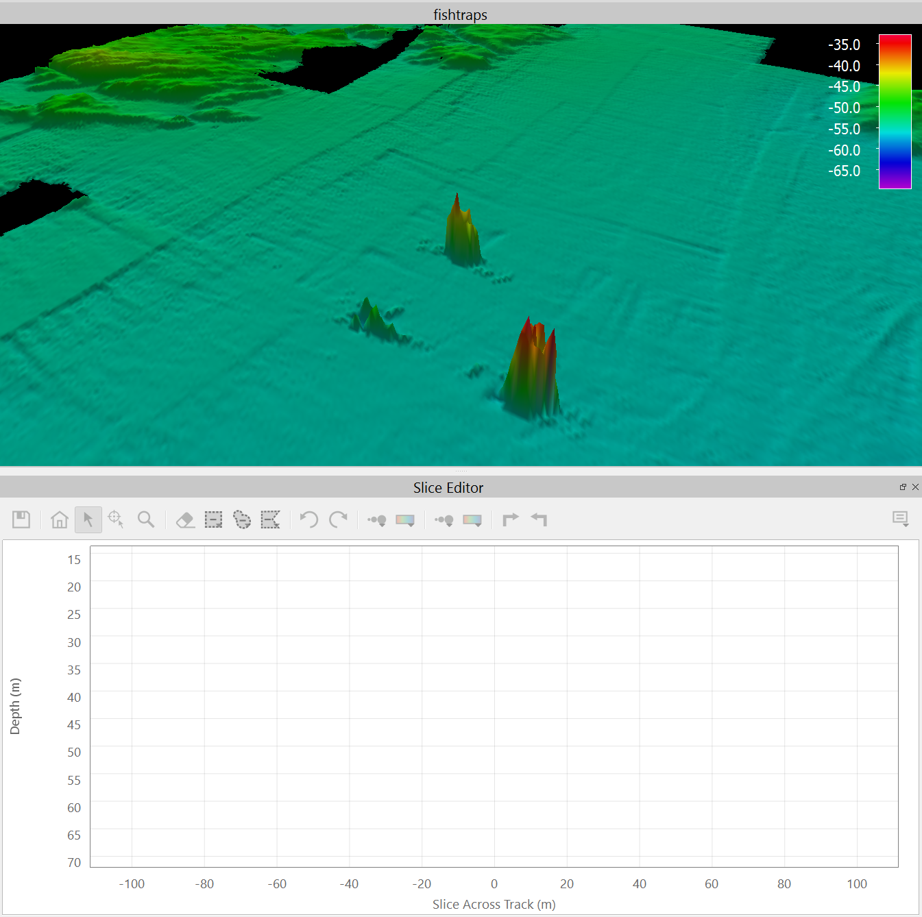
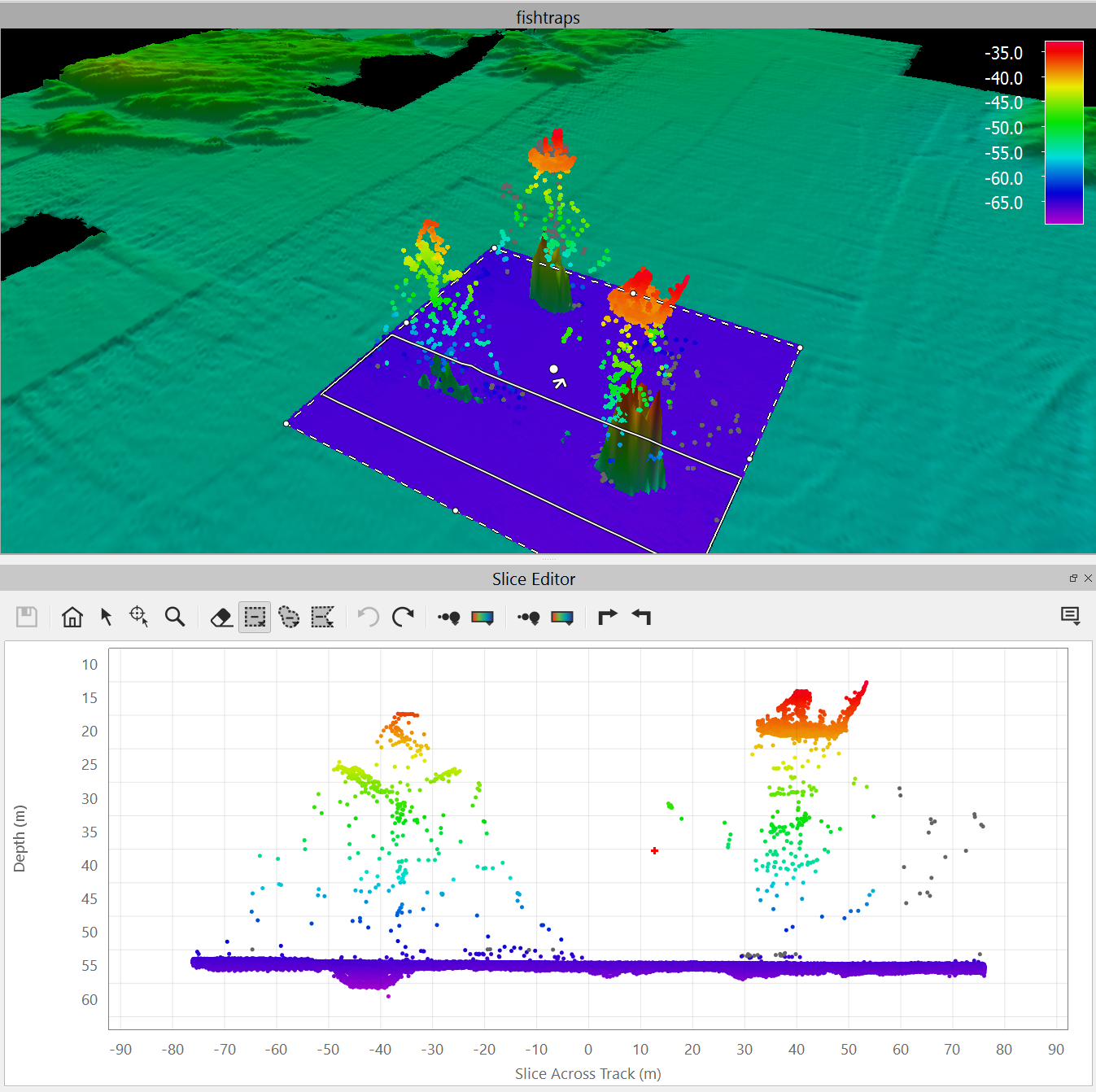
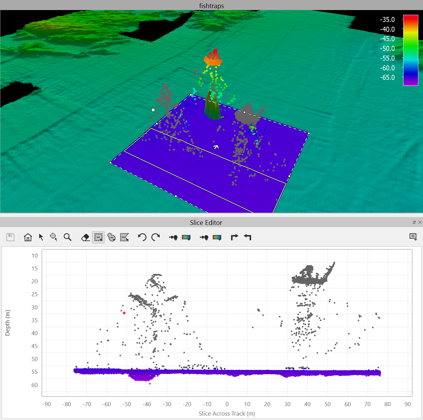
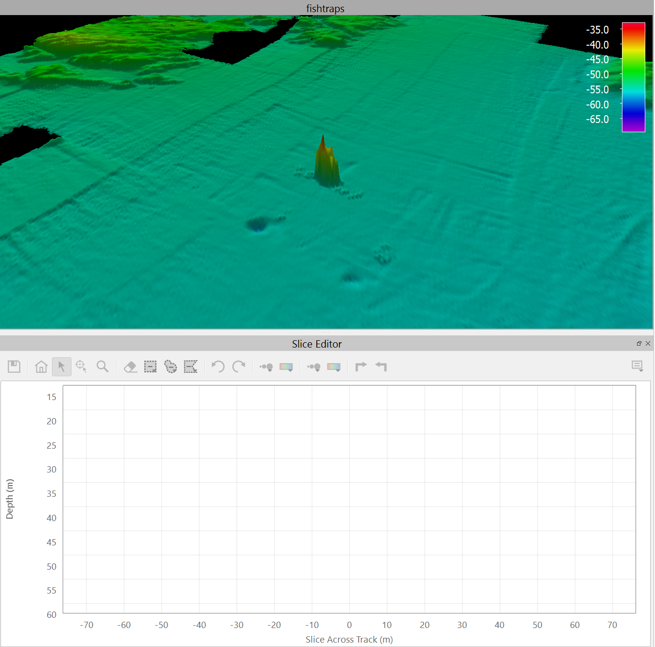
Sounding editing occurs inside the Slice Editor Widget. By default, as you select soundings in the Slice Editor, they are automatically rejected. Depending on what you have set for the Show Soundings option, you can also see the rejected soundings as gray points. All accepted soundings are colored by the current Color By mode. A before/after example is shown below with Show Rejected on. This examples uses the Save Edits Manually so the surface will not update until you click on the Save icon in the toolbar. This example uses a simple rectangular selection.
The images below were intentionally not updated for this version as the behavior remains the same. The only change is with the addition of new toolbar icons which are described above.
As you can see, the slice view and the 3D view are the same. If you turn off Show Rejected, you will not see the soundings that you have rejected. Below is another example using the Save Edits Instantly option. In this case, all of the soundings above the primary seafloor are removed. There are 4 images which represent Before Edits, During Editing, After EditingSelection and After Editing.
When sounding editing, simply hold down the SHIFT key while using the left mouse to pan
JavaScript errors detected
Please note, these errors can depend on your browser setup.
If this problem persists, please contact our support.