Edit Processing Parameters option of raw sonar files context menu
What it Does
This dialog provides access to key options used during raw sonar processing.
General Description
The processing settings dialog configures settings in the processing pipeline. This configuration controls all of the settings that affect the mathematical operations that are required to compute sounding footprint location. The settings can be edited for one or more files at a time, this is controlled by the items that you've selected in the Raw Sonar Files tree prior to launching the dialog. The dialog will highlight which types of settings have conflicting values among the set of files that you are configuring. In this manner, you can maintain different settings between files when you need or make a global change to all the configurations if you need to. For example, some files may use GNSS heighting and others may use tide for vertical referencing. You can select all of the files and change the sound speed processing strategy without worrying about losing the configuration settings you may have set for vertical referencing. Each page of the processing settings is described below.
General Notes
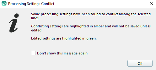
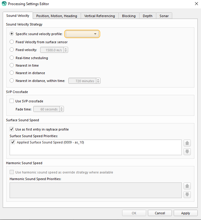
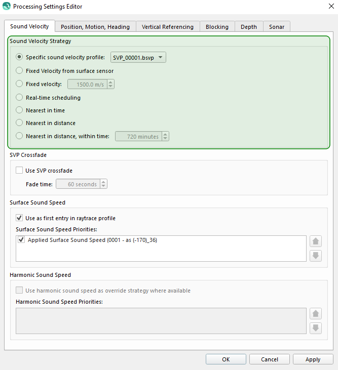
Processing Settings Conflict
If multiple lines are selected with conflicting settings a warning dialog will be shown.
In the dialog conflicting settings will be highlighted amber (see top image below). Other settings can be modified and saved without affecting the conflicting settings. If an option is selected for a conflicting setting it will then be highlighted green (see bottom image below) and saved to all selected raw sonar files.
System Prioritization
There can be multiple source systems for a given type of sensor data. Qimera allows for prioritization, or ordering and enabling or disabling of those systems for each type of sensor data.
Each source can be individually enabled/disabled and prioritized. To prioritize select the source and use the arrow buttons to the right of the frame. Sources are prioritized from top to bottom.
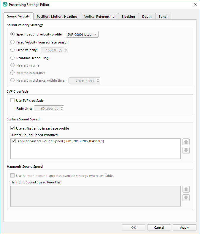
Sound Velocity
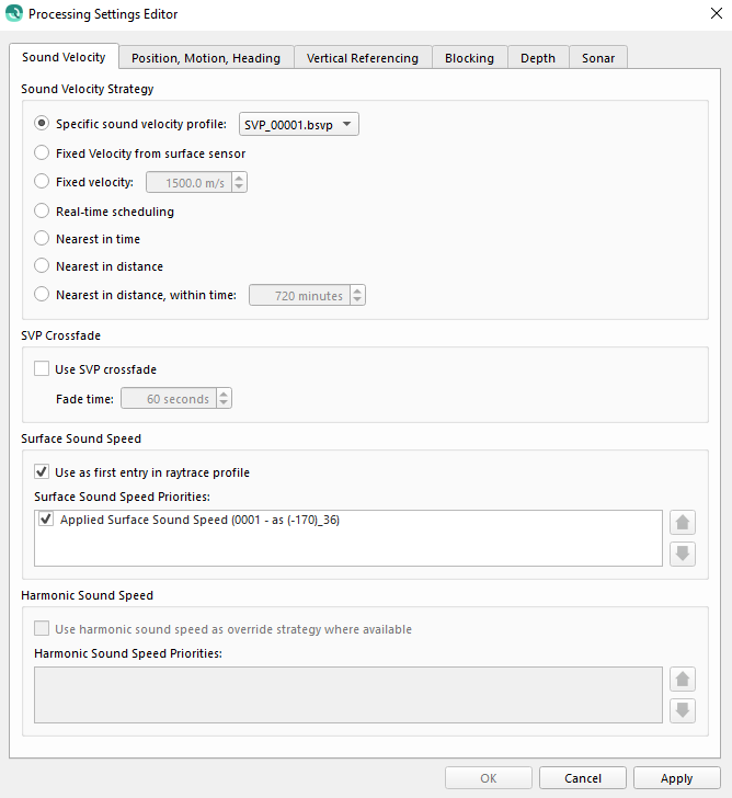
The Sound Velocity settings tab is used for configuring the sound velocity, or sound speed used during ray tracing.
Sound Velocity Strategy
There are several sound velocity strategies. Qimera will protect you from choosing nonsense SVP strategies by disabling strategies for which there is insufficient information in the SVP files to allow correct lookup. For example, if one or more SVP files do not contain a valid observation time, then all time-based lookups will be disabled. Likewise for position. In the example above, the two distance based strategies are disabled because some of the SVPs do not have a valid position. The time and position for SVP files can be updated in Qimera's SVP Editor. Once you enter this info for all of the vessel's SVPs, you can then revisit the processing configuration dialog to choose the appropriate strategies.
Strategy
Description
Specific sound velocity profile
This option will only use the selected sound velocity profile for all selected raw sonar files.
Fixed Velocity from surface sensor
This option will use the surface sound speed sensor value to represent the entire water column. Strictly speaking, no ray tracing is done. Instead the surface sensor used for beamforming is used to scale the travel-time into a range measurement.
Fixed velocity
This option will use the input sound speed value. Strictly speaking, no ray tracing is done. Instead the specified value is used to scale the travel-time into a range measurement.
Real-time scheduling
If the imported raw sonar files include sound velocity profiles this option will use the profile from the time it is included in the sonar file.
Nearest in time
This option will use all available profiles and select the profile nearest in time for each ping. All SVP casts must have their observation time entered to allow this option.
Nearest in distance
This option will use all available profiles and select the profile nearest in distance for each ping. All SVP casts must have their position entered to allow this option.
Nearest in distance within time
This option will use profiles within the given time window and select the profile nearest in distance for each ping. All SVP casts must have their observation time and position entered to allow this option.
SVP Crossfade
Use SVP crossfade
This option will enable or disable the use of SVP crossfade. The crossfade will blend the small transition zone when switching between one SVP to another, this occurs when using Sound Velocity lookup strategies like "Nearest in distance" and "Nearest in Time". When this option is enabled, you can adjust the Fade Time, which is the time in seconds that is used for blending the two SVPs. Qimera will automatically find the transition zone and use the Fade time window to blend from one SVP to the next SVP, smoothing the transition.
Surface Sound Speed
Use as first entry in ray trace profile
This option will enable or disable the use of surface sound speed as the first entry into the SVP for ray tracing.
Surface Sound Speed Priorities
The Surface Sound Speed Priorities lists all available sources of surface sound speed. Each source can be individually enabled/disabled and prioritized. To prioritize select the source and use the arrow buttons to the right of the frame. Sources are prioritized from top to bottom.
The harmonic sound speed will override the strategy configured above for both surface sound speed and the entire water column when available and enabled.
Use harmonic sound speed as override strategy where available
This option will enable or disable the use of the harmonic sound speed for both surface sound speed and the entire water column.
Harmonic Sound Speed Priorities
The Harmonic Sound Speed Priorities lists all available sources of surface sound speed. Each source can be individually enabled/disabled and prioritized. To prioritize select the source and use the arrow buttons to the right of the frame. Sources are prioritized from top to bottom.
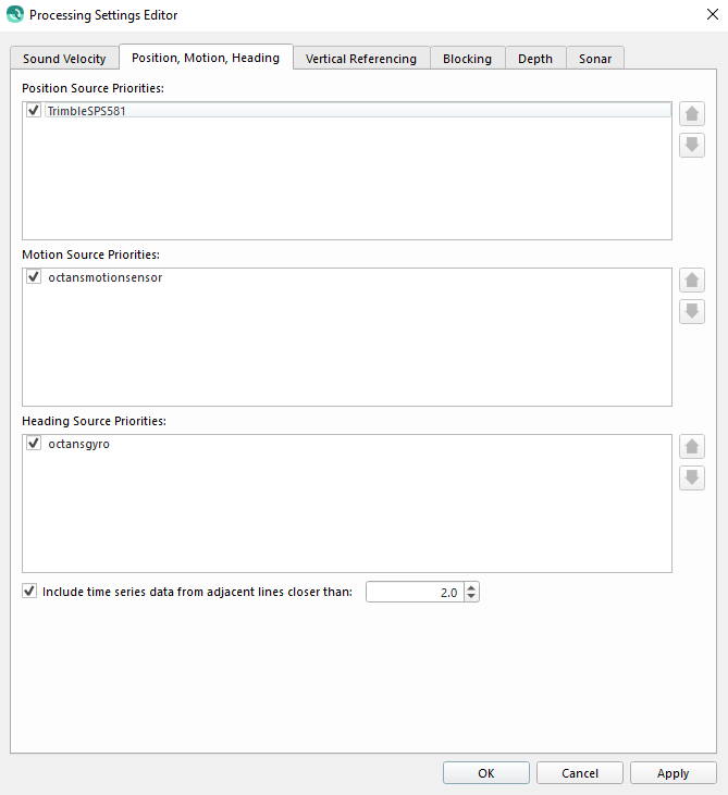
Position, Motion, Heading
The Position, Motion, Heading settings tab provides source prioritization for position, motion and heading systems.
Position Source Priorities
The Position Source Priorities lists all available sources of position. Each source can be individually enabled/disabled and prioritized. To prioritize select the source and use the arrow buttons to the right of the frame. Sources are prioritized from top to bottom.
Motion Source Priorities
TheMotion Source Prioritieslists all available sources of motion which includes roll, pitch and heave. Each source can be individually enabled/disabled and prioritized. To prioritize select the source and use the arrow buttons to the right of the frame. Sources are prioritized from top to bottom.
Heading Source Priorities
The Heading Source Priorities lists all available sources of heading. Each source can be individually enabled/disabled and prioritized. To prioritize select the source and use the arrow buttons to the right of the frame. Sources are prioritized from top to bottom.
Include time series data from adjacent lines
If enabled, this option will included source data from adjacent raw sonar files that terminate or begin within the specified time. This can be useful if small data gaps are noticed where raw sonar files are terminated and restarted.
This is specifically useful for systems that have a low update rates. For example if using a 1 Hertz positioning system and logging is started between position records it is likely that the first ping will not be processed. By including adjacent source data the position records can then be interpolated for those pings.
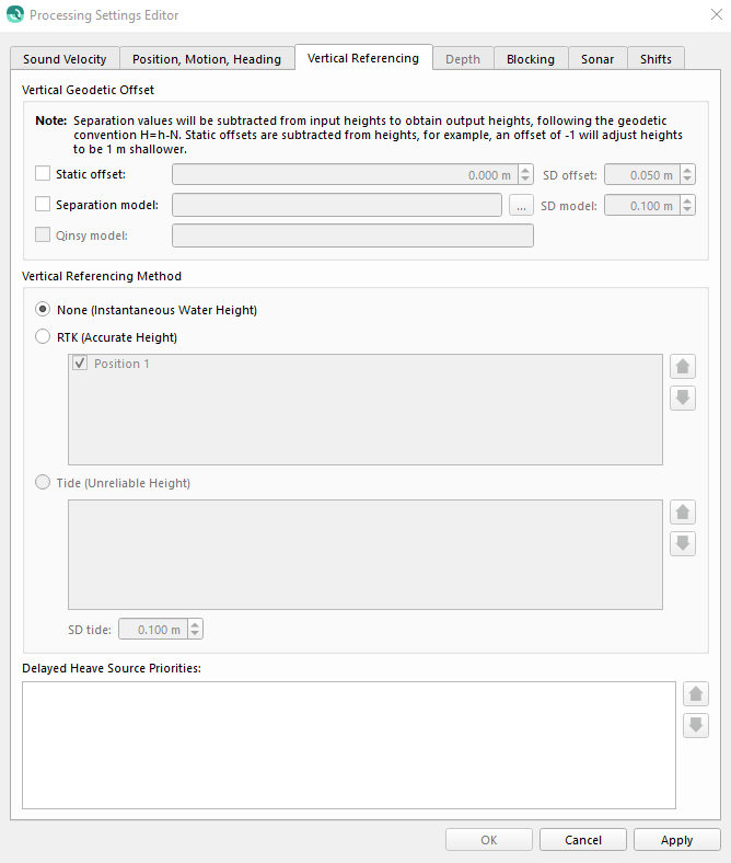
Vertical Referencing
The Vertical Referencing settings tab provides applying vertical offsets, selecting the vertical method, and prioritizing delayed heave
Note for underwater vessels the vertical referencing settings only affect the vertical position of the vessel but do not affect the depth used for ray tracing. See Depth Settings below for further discussion.
Vertical Offset
In this section vertical offsets can be enabled and configured.
Please note that Vertical Offsets are applied to all vertical referencing methods. If offsets are only applicable to a specific vertical referencing method they must be enabled or disabled appropriately when switching method.
Eg. If using Tide as your Vertical Referencing Method these will be in addition to any offsets configured in a tide strategy.
Type
Description
Static Offset
This is a single offset that will be applied universally.
Suggested use:
With GNSS/GPS heighting, if working in a small area this could be used to offset from the ellipsoid to the local tide datum.
With Tide heighting if tidal data is reference to MSL this could be used to offset to the Chart Datum.
Separation model
You may select an SD surface file. If not in the project's datum you will be prompted to transform the surface. The offset that is applied is based on the vessel location on the surface.
Suggested use:
When working in larger areas with GNSS/GPS heighting the tidal datum is likely to change relative to the ellipsoid, use of a geoid model can be employed to offset to local MSL.
When working in an area with highly variable water height datums, such as a river, a model of the river datum offsets coupled with a water height gauge imported as tides could be employed.
Qinsy model
This is not a configurable option. This displays any Geoid file configured in Qinsy Database files that will be applied to vertical referencing.
Vertical Referencing Method
Method
Description
None (Instantaneous Water Height)
If this method is selected the water depth used during ray tracing will be used to vertically position the vessel.
Included corrections:
Draft
Squat
Heave or Delayed heave if available
Vessel lever arms
RTK (Accurate Height)
If this method is selected the GNSS, GPS, or IMU heights will be used to vertically position the vessel. The only correction applied are the lever arm offsets.
Note: For height data less than or equal to 25 Hz the heave data will be combined to create a high frequency time series.
Tide (Unreliable Height)
This method can only be selected if tide file has been imported that overlaps the selected line.
If this method is selected the tide height will be added as a corrector to the water depth to vertically position the vessel.
Included corrections:
Draft
Squat
Heave or delayed heave if available
Vessel lever arms
Tide height
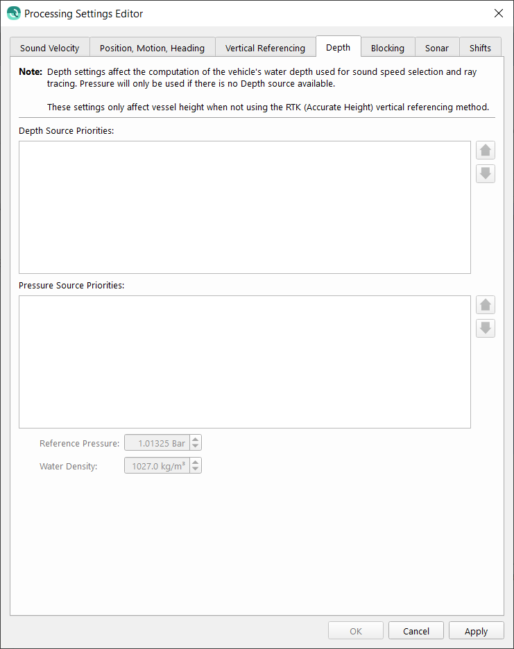
Depth
The depth settings tab is used for configuring settings related to underwater vessels. These settings will be used in the calculation of the water depth of the vessel primarily for sound speed selection. Priority is given to depth sources if both depth and pressure are available. In this scenario, if you want to force the use of pressure instead of depth, you can untick the depth time-series in their priority list.
If depth or pressure sources are available and enabled the water depth calculation will only include sensor depth/pressure and the lever arm corrections necessary to translate this to the CoG of the vessel. This affects the None or Tides vertical referencing method but does not affect the RTK (Accurate Height) vertical referencing method.
Depth Source Priorities
The Depth Source Priorities lists all available sources of vessel depth. Each source can be individually enabled/disabled and prioritized. To prioritize select the source and use the arrow buttons to the right of the frame. Sources are prioritized from top to bottom.
Pressure Source Priorities
The Pressure Source Priorities lists all available sources of pressure. Each source can be individually enabled/disabled and prioritized. To prioritize select the source and use the arrow buttons to the right of the frame. Sources are prioritized from top to bottom.
Reference Pressure and Water Density
These settings are used to convert the pressure data to depth. If scale factors or offsets are needed for specific sources they can be configured in the Qimera Vessel Editor.
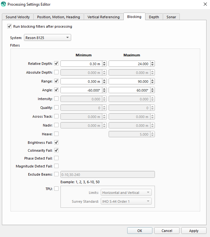
Blocking
The Blocking settings tab provide configuration to exclude soundings based on filter options. All filters are disabled by default, to enable check the box next to the name.
All soundings outside the minimum and maximum for the given filter will be excluded from surface and flagged as
Method
Description
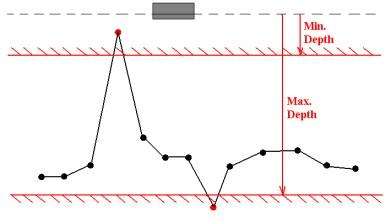
Relative Depth
This filter will clip all data that falls outside the specified depth range, as measured from the echosounder transducer.
Depth values should be entered as positive for values below the transducer, or negative for values above the transducer.
An example is shown below:
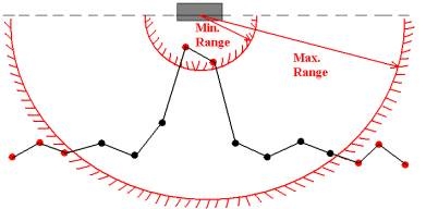
Range
This filter clips all data that falls outside the specified range (distance) as measured from the transducer.
An example is shown below:
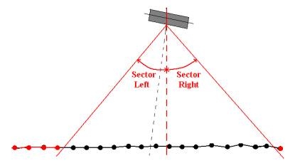
Angle
All data that falls outside the given angles to the port (negative) and starboard (positive) side of the lead line through the center of the transducer is clipped.
Port and starboard side are defined relative to the heading of the transducer, which is normally the same as the object heading on which the transducer is mounted. The advantage of the sector exclusion over the beam exclusion is that the beams are removed depending on the direction where they are coming from instead of always removing the same number of beams.
When the ship is experiencing significant roll the angle exclusion will allow for that roll angle and remove more beams on one side of the transducer than on the other side.
An example is shown below:
Intensity
Data will be excluded based on the Intensity (backscatter) values.
Useful for interferometric systems.
Quality
This filter will exclude beams outside the min/max quality values.
Absolute Depth
This filter will clip all beams with absolute depth values (which include any height) outside the specified min/max values.
Heave
This filter removes the depth observations when the change in heave between two consecutive measurements is greater than the entered value.
The entered value for this filter is the rate of change of the heave, and not the actual heave itself.
TPU Horizontal
The Total Propagated Uncertainty (TPU) of a point is a measure for the accuracy to be expected for such a point, when all relevant error sources are taken into account.
This filter will exclude beams where the horizontal TPU exceeds the max value.
TPU Vertical
The Total Propagated Uncertainty (TPU) of a point is a measure for the accuracy to be expected for such a point, when all relevant error sources are taken into account.
This filter will exclude beams where the vertical TPU exceeds the max value.
Exclude Beams
Excludes certain beams solely based upon the number of the beam as defined by the multibeam manufacturer. This filter is useful for switching off beams which are providing “bad” data.
Although this filter can exclude the outer beams, a better option is the 'Sector outside' filter.
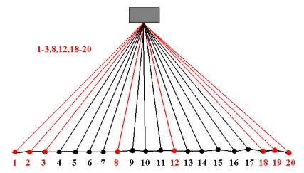
Groups of beams can be defined by a hyphen (-) between them; groups or beams can be separated using a colon (:). An example is shown below.
This example will exclude beams 1 to 3, beam 8, beam 12 and beams 18 to 19 when creating the DTM or grid.
Across Track
This filter will exclude beams outside the min/max across track distance.
Nadir
This filter will exclude beams inside the min/max across track distance.
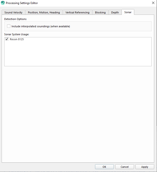
Sonar
The Sonar settings tab provides control over system pings that will be included in the generated QPD. More specifically, the system will be included but all pings will be excluded if the Sonar System Usage checkbox is unchecked for a system. You can also decide to include interpolated soundings by checking the box in the Detection Options, this is only applicable for Kongsberg .all and .kmall formats. If this interpolated soundings box is left unchecked, the interpolated soundings will be flagged as rejected soundings. This setting can be overridden when exporting the file to a GSF by a checkbox in the export dialog.
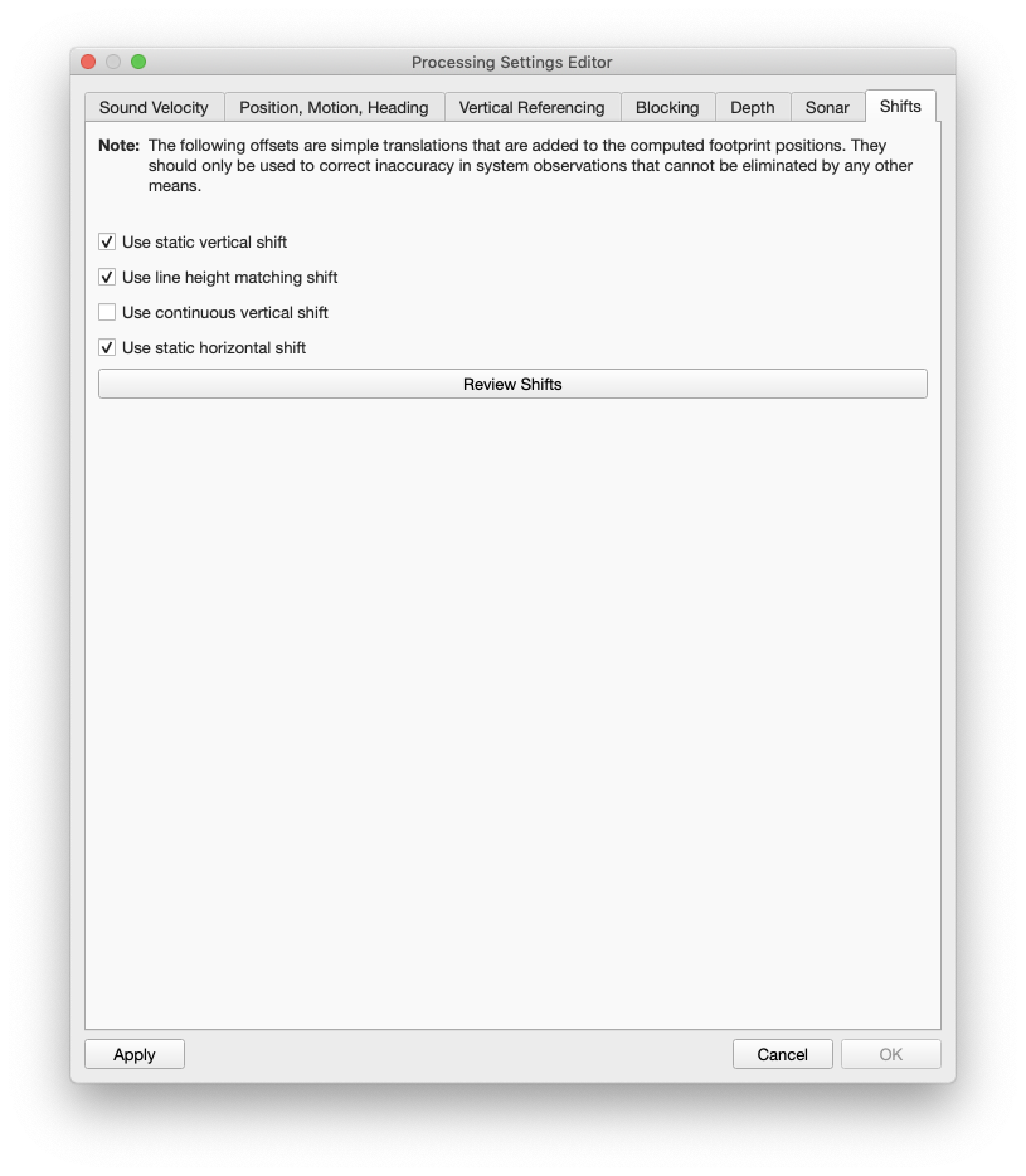
Shifts
The Shifts Settings tab allows you to enable or disable the use of vertical or horizontal shifts in your files. Shifts are applied to every ping in order to offset soundings by a computed or set XY or Z displacement. These check boxes do not delete the numerical data associated with the specific shift, they merely enable or disable the use of the shift in the final sounding location computation.
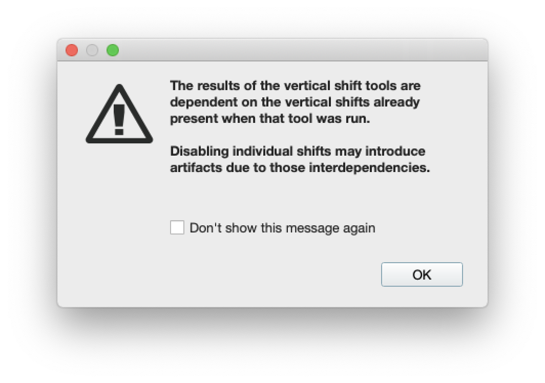
In the case of vertical shifts, if you have used more than one vertical shift, and you later disable one of the shifts, you will get the following warning dialog. This is because each shift may be dependent on a shift that was calculated earlier in your processing. It is recommended that you determine the best shift methodology that fits your particular needs before using more than one vertical shift tool.
Use Static Vertical Shift
That Static Vertical Shift value is computed using the Static Vertical Shift tool. It can also be set, adjusted or cleared using the Adjust Vertical Shifts tool. Use this option to control when to use the static vertical shift.
Use Line Height Matching Shift
The Line Height Matching shift value is computed using the Line Height Matching tool. It can also be cleared using the Adjust Vertical Shifts tool. Use this option to control when to use the line height matching shift.
Use Varying Vertical Shift
The Varying Vertical shift value is computed using the Varying Vertical Shift tool . It can also be cleared using the Adjust Vertical Shifts tool. Use this option to control when to use the varying vertical shift.
Use Static Horizontal Shift
The Static Horizontal shift value is computed using the Static Horizontal Shit tool. It can also be set, adjusted or cleared using the Adjust Static Horizontal Shift tool. Use this option to control when to use the static horizontal shift.
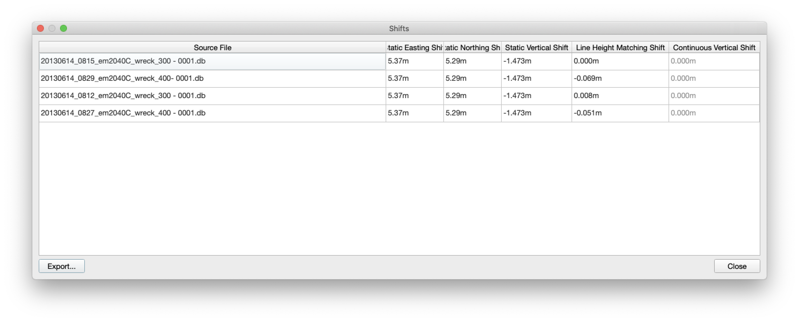
Review Shifts Button
This button brings up the Shifts dialog that shows you all of the shifts for the selected raw sonar files. This table is not an editable and is for display purposes only. If a shift type is unchecked, the column value will appear disabled in the table.
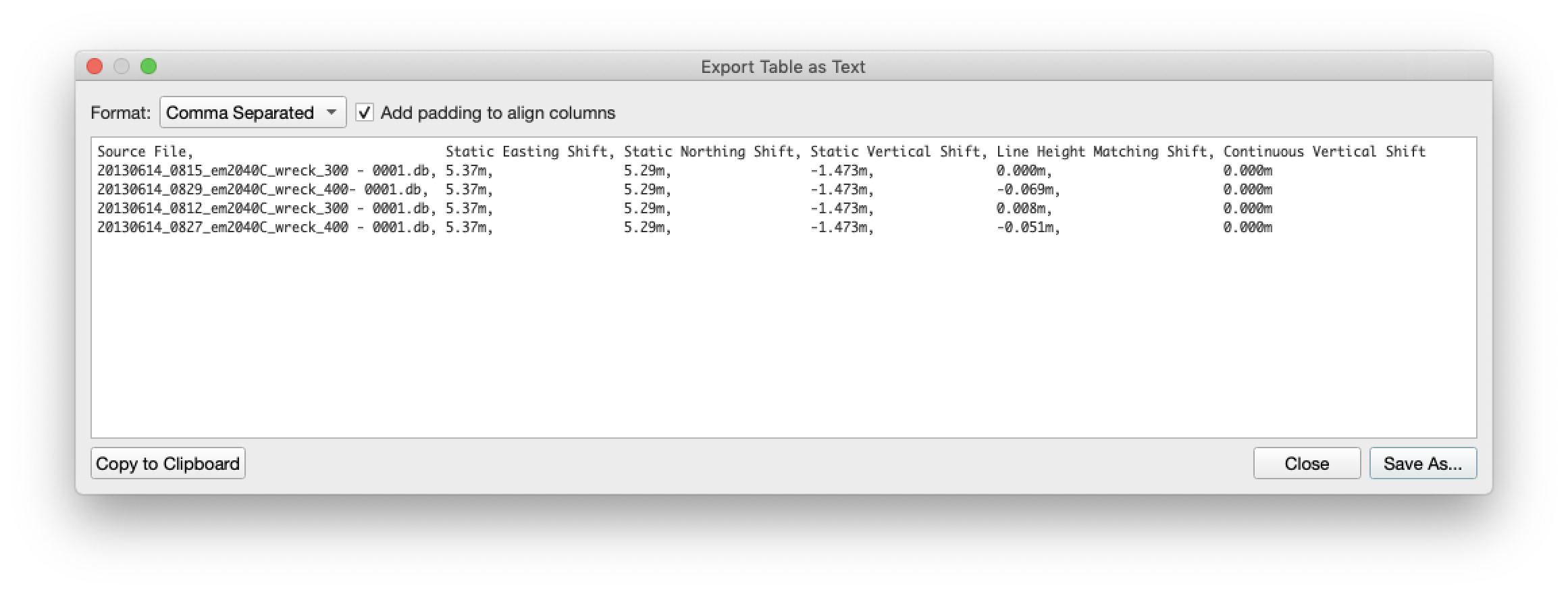
Export Button
Click on the Export button to get the table exporter. Here you can copy the values to the clipboard or save them as a .csv file.