Vessel Editor option from Tools menu of Main Menu bar
Context menu of Raw Sonar Files → Edit Vessel Configuration
What it Does
The Vessel Editor is used to review and edit all information regarding a particular sensor or system.
General Description
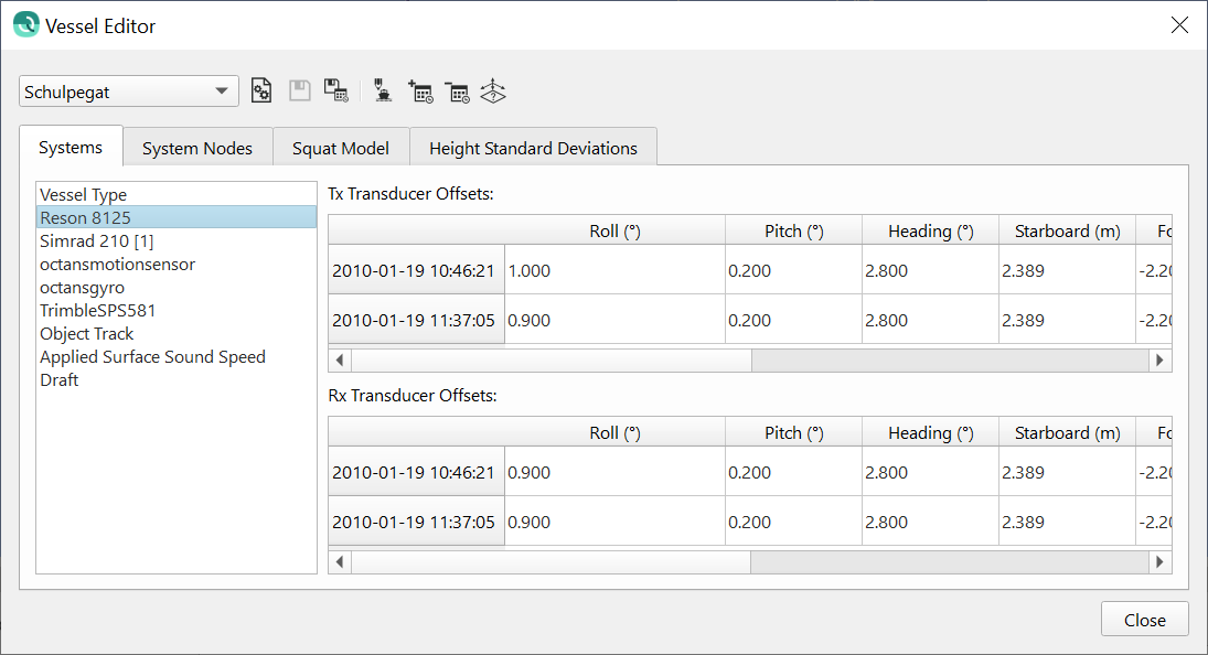
Editing for sensors and systems includes location on the vessel, angular alignment, latency, sign conventions and measurement standard deviations (SD) used for calculating sounding footprint uncertainty. This data is extracted during the initial import of Raw Sonar Files and is stored inside the Qimera project in the Metadata folder for the line. Any edits that are performed and saved will trigger a reaction from the Dynamic Workflow engine. The Systems tab provides a list of systems associated with the vessel in the left pane, and table of entries on the right containing offset information. The System Nodes tab lists all systems associated with the vessel, as well as their respective node. The Squat Model tab allows the user to provide a squat model. The Height Standard Deviations tab allows the user to enter the uncertainty pertaining to height variables such as Squat, Tide and Load. Control of the display is managed by the toolbar.
Toolbar
Combo Box
Qimera allows users to create projects with data from multiple sources, of which each may have a unique vessel configuration. The combo box allows for vessel selection. For projects with a single vessel, the combo box will be drawn in gray.
Open Configuration
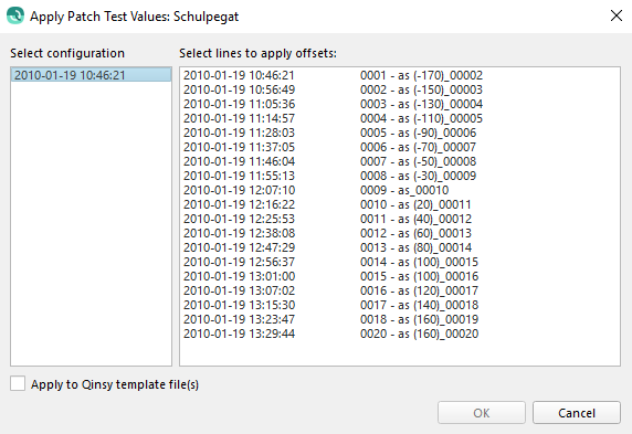
This will allow you to load a patch test or wobble analysis session file and apply it to the existing vessel configuration. A file selection dialog will allow you to choose the patch test or wobble analysis session output file, and you will then be presented with a list of source item start times to which you can apply the new configuration (shown below) The configuration values, e.g. roll offset of the multibeam head, will replace the value that is currently stored in the vessel configuration. This avoids the problems of accidental double application that could occur if the values from the patch test session were added to the existing values. The tickbox to "Apply to Qinsy template file(s)" will apply patch test offsets to template.db files that are found in the same location as the original .db files. At the moment, the only values that are applied are patch test values for multibeam systems.
Save
This will save any edits made to any parameter in the vessel configuration. It will trigger a reaction from the Dynamic Workflow engine.
Save Configuration
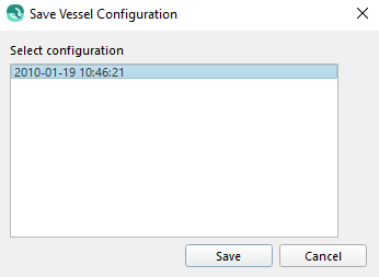
This will allow you to save a specific date time configuration as a "Template" for use during loading of more raw sonar files or during Automatic Raw File import. You will be presented with a dialog (shown below) to select the date/time configuration to save as a template. These files are saved to your project\vessel folder. If you use a template configuration during file loading, it will override any vessel configuration information extracted from the raw sonar file.
Edit Vessel Name
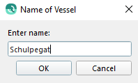
This will let you change the name of the vessel as it appears in the combo box. Some multibeam file formats specify a vessel name whereas others do not. In the first case, Qimera will use the vessel name encoded in the incoming data files. In the latter case, the user must specify a vessel name upon import of the first file. Later, they must import sessions of the same file type, which will allow the user to choose from a set of vessels previously created for the incoming file type. Renaming a vessel file does not trigger any reaction from the Dynamic Workflow engine.
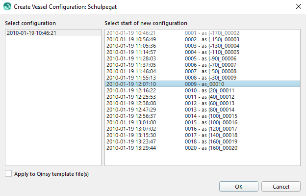
New Date/Time Entry
Qimera stores a vessel configuration file for each source item in the metadata directory associated with the source item. When the vessel editor is run, all of these files are loaded and only the earliest instance of each unique configuration is shown to you. This button allows you to create a new configuration by presenting you with a dialog of all the possible source item start times (shown below). Once a start time for the new configuration is selected, an entry is made in all the time based tables, and you can then make the necessary modifications and save your changes. Saving the vessel configuration will trigger a reaction from the Dynamic Workflow engine, but only for the files that are affected by the change in configuration. In this case, the Dynamic Workflow will trigger for only the files that are affected by the new time based entry.
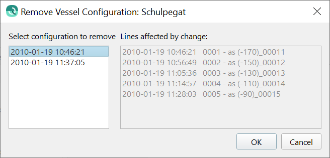
Remove Date/Time Entry
This button presents you with a dialog listing all the current Date/Time entries for the selected vessel at the left. In the right column, the lines that will be affected by the removal of the entry are shown. Upon clicking 'OK' the selected Date/Time entry will be removed. If it is the first entry, the settings from the second entry will be applied to the files in the first. In all other cases, the settings from the previous Date/Time entry will applied to those in the selected entry. Changes are not saved immediately and can be reviewed in the Vessel Editor dialog.
TPU Editor
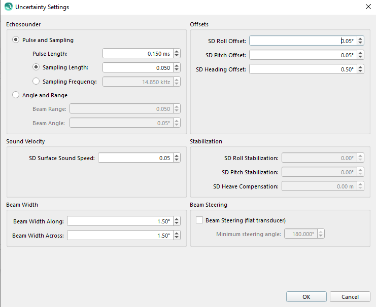
This button will allow you to modify the sensor measurement uncertainty settings. These values are used to compute each sounding footprint's estimated uncertainty. The TPU button is sensitive to the system list's current selection and the dialog that results will vary with system types. Edits to TPU parameters will trigger a reaction from the Dynamic Workflow engine once the vessel file is saved. For simple sensors such as a positioning system, you will only be updating the estimated sensor standard deviations. For a more complex system like a multibeam, you will be editing the parameters that are used by an uncertainty model. The dialogs for each system type are shown below. Currently, the only data type that provides this type of information during import is a Qinsy .db file. For all other types of source items, Qimera uses the same default sensor uncertainty parameters that are used by Qinsy when setting up drivers for any given system.
Certain fields within the Uncertainty Settings dialogs will become highlighted in red if the values are suspected to be out of expected range.
Multibeam
The uncertainty of the multibeam measurements (range and angle, primarily) are either estimated using an uncertainty model that can use pulse length and sampling rate (Pulse and Sampling method), or specified directly using the Angle and Range method. The uncertainties in the installation angles, including patch test alignment angles, are specified in the Offsets section. Most modern multibeam systems use sound speed measurements from a surface sensor, and the uncertainty from this sensor can be specified in the Sound Velocity section. If a system is stabilized for roll, pitch or heave (only available for Qinsy data for devices that are configured as such in the Qinsy driver), the stabilization uncertainties can be specified in the Stabilization section. The beam width in the fore-aft and across-track direction are additional parameters that are used to inform the multibeam uncertainty model, and these can be specified in the Beam Width section. The Beam Steering section is only used for Qinsy data for devices that support such a configuration and should not be enabled otherwise. The default values shown in the dialog below are used for source items that do not report these parameters directly.
Motion Sensor
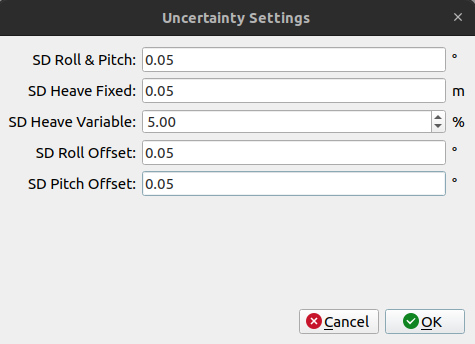
Motion sensor uncertainty settings can be configured for the measurements themselves and also for the offsets, i.e. the patch test angular misalignment angles. Heave sensor specifications typically indicate that heave uncertainty has a fixed component, in linear units, and a variable component that varies as a percentage of the heave amplitude. All of these can be specified in this dialog. The default values shown in the dialog below will be used for source items that do not report these parameters directly. These sensor uncertainty values will be replaced with uncertainties estimated by the sensor if the data from the sensor supports this. Currently, this is only available for POSMV (.000) files and for POSPac MMS SBET/RMS files.
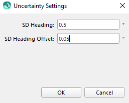
Heading Sensor
The uncertainty of the heading measurement itself and of the angular misalignment offset can be specified in this dialog. A default value of 0.01 degrees and 0.05 degrees is used for source items that do not report these parameters directly. The heading uncertainty specified in this dialog will be replaced with uncertainties estimated by the sensor if the data from the sensor supports this. Currently, this is only available for POSMV (.000) files and for POSMV MMS SBET/RMS files.
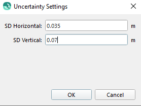
Position Sensor
The uncertainty of the positioning system can be specified in this dialog. The defaults of 0.5 m and 1.0 m represent what is typically achievable with differential positioning corrections. These default values are used for source items that do not report these parameters directly. The vertical uncertainty of the positioning system is only included in footprint uncertainty calculations if the height is used for vertical referencing. The positioning system uncertainties specified in this dialog will be replaced with uncertainties estimated by the sensor if the data from the sensor supports this. Currently, this is only available for POSMV (.000) files and for POSMV MMS SBET/RMS files, or for positioning data streams from Qinsy (.db) files for sensors that support this in their particular driver configuration.
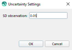
Surface Sound Speed Sensor
The uncertainty of the surface sound speed sensor used in beamforming is specified in this dialog. A default of 0.05 m/s is used for source items that do not report this directly. This value will over-ride the value in the multibeam uncertainty settings dialog if data from a surface sound speed sensor is found.
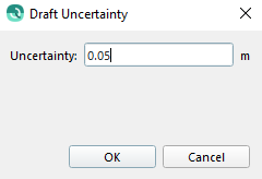
Draft
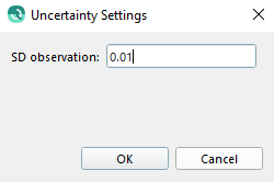
The uncertainty of the draft measurement can be configured in this dialog. A default value of 0.05 m is used for source items that do not report this directly.
Depth
The uncertainty of the depth measurement can be configured in this dialog. A default value of 0.01 m is used for source items that do not report this directly.
Pressure
The uncertainty of the pressure measurement can be configured in this dialog. A default value of 0.01 bar is used for source items that do not report this directly.
Systems Tab
The systems tab presents you with a list of systems that are associated with the vessel along with a table of time tagged entries that present various sensor parameters. The contents of the system list will vary with the type of source files that are imported into Qimera. These variations are summarized below in two groups:
Group 1: Multiple sensor streams supported. In general, these files can support observations from multiple redundant sensors and their data streams may or may not be present. All systems found in the files will be extracted into the Qimera vessel file. The file formats also typically indicate the primary data stream in the event of the multiple redundant data streams. Data streams typically come from named sensors, Qimera attempts to preserve the system naming when creating the vessel file.
Qinsy .db files: Each system that is used in the mathematical computation of sounding footprint locations is included in the Qimera version of the vessel file. All other systems are ignored, for example a wind speed sensor.
Kongsberg .all files: This format is for Kongsberg systems only and thus it has a limited set of possible configurations. For example, there can be up to 3 positioning systems present and there can be up to 2 motion sensors. Qimera will create a system for all of the possibilities, even if there is only data from a single system. This allows Qimera to react correctly with configuration changes, such as the addition or removal backup position or motion sensors during acquisition. Presence of these systems in the vessel configuration does not imply that there is data available, this must be confirmed by examining the time-series data available for each source item.
Hypack .hsx files: This format can contain a number of systems of varying types. Qimera creates a sensor for each one found in the HSX file. Configuration changes done in real-time, e.g. addition or removal of a sensor, will result in a different vessel file.
Group 2:It is our understanding that the following formats can only support a single motion and single position system. Observation systems are created for this minimal set in the vessel configuration regardless of whether or not there is data present in the source file. This allows Qimera to elegantly deal with configuration changes done during acquisition in that the Qimera user will always be dealing with the same vessel configuration regardless of the absence/presence of various data streams. Presence of these systems in the vessel configuration does not imply that there is data available, this must be confirmed by examining the time-series data available for each source item.
Reson .s7k files: Position, motion, heading, surface sound speed and pressure/depth systems are created.
EdgeTech JSF files: Position, motion, heading and surface sound speed systems are created.
GSF files: Position, motion, heading, surface sound speed systems are created.
ELAC XSE files: Position, motion, heading, surface sound speed systems are created.
R2Sonic .r2sc files: surface sound speed systems are created. Position, motion, heading information is not contained in the binary file.
The contents of the table of entries will change depending on the currently selected system in the system list.
Multibeam systems
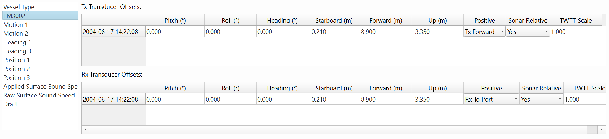
Just a general note first before describing the system parameters. Qimera allows you to specify the transmitter and receiver parameters separately to accommodate the general case where this is required. This is absolutely necessary for deep water systems and occasionally necessary for shallow water systems, especially dual head configurations with a shared transmitter. Some sonar systems make a correction to travel-time and/or angles to correct for the separation between transmitter and receiver. Qimera correctly detects and pre-configures this for Qinsy .db format, Kongsberg .all format and Teledyne-Reson .s7k format. For Qinsy users, the option to use a "common acoustic center" forces the location of the transmitter and receiver to be at the same location mathematically in the processing. For these users, they will see a transmitter and receiver with identical locations. In the event that you have a system which already corrects for this, you will still find a transmitter and receiver entry for your multibeam system. In these cases, if you need to correct the location or orientation of the transmitter you will need to apply the same correction to the receiver, and vice versa.
Pitch/roll/heading angular offsets: Either determined through a marine surveyor's measurements or through a patch test calibration.
Starboard/Forward/Up location: Sensor position relative to the CoG. These offsets are used to establish the 3D position of the sensor relative to the CoG.
Beam angle sign convention for both transmitter and receiver: The sign convention for the beam angles. This is automatically set for all formats but errors in configuration of the sonar or the acquisition system may result in users needing to correct for this here. When a MBES system is logged in Qinsy, the sign convention is 'standardized' to Qinsy's convention in the logged .DB file.
Beam angle reference convention for both transmitter and receiver: Specifies whether beam angles reported by the system are relative to the sonar frame or to the vertical. Some multibeam systems that perform motion stabilization report the corrected beam angles (Sonar Relative = No) whereas others report the raw sonar angles regardless of whether they are motion stabilized or not (Sonar Relative = Yes). Most modern systems report angles relative to the sonar (Sonar Relative = Yes). This setting is automatically set for Qinsy .db files, Reson .s7k and Kongsberg .all files. HSX users may find that this parameter needs to be adjusted.
Two-way travel time (TWTT) scale: Specifies a travel-time scaling factor, with a default value of 1.0, that a user can modify to recover from cases where the travel-time is incorrectly encoded in a particular incoming source file. This is not a common occurrence, however, in our work with GSF files in FMGT, we have seen several instances where the travel-time is incorrectly encoded by the source application that writes out the GSF. In some cases, the travel-time is reported as a one-way travel-time (thus a scaling factor of 2.0 would be required to recover from this). In another example, the travel-time was scaled by a factor of 100 (thus a scaling factor of 0.01 would be required to recover from this).
Laser systems:
Pitch/roll/heading angular offsets: Either determined through a marine surveyor's measurements or through a patch test calibration.
Starboard/Forward/Up location: Sensor position relative to the CoG. These offsets are used to establish the 3D position of the sensor relative to the CoG.
Echosounder systems:
There are currently no configurable settings. Position and orientation offsets can be reviewed.
Motion sensor systems:
Latency: Time latency of the reported measurements, this number is added to the requested time prior to any lookup of data from this sensor.
Heave delay: Additional time delay of the reported heave measurements. Total heave latency is the sum of system latency and heave delay.
Pitch/roll/heading angular offsets: Either determined through a marine surveyor's measurements or through a patch test calibration.
Starboard/Forward/Up location: Sensor position relative to the CoG. These offsets are used to migrate heave measurements from the reported location to the desired location (usually the CoG).
Angle and heave sign conventions. This is automatically set for all formats but errors in configuration of the motion sensor or the acquisition system may result in users needing to correct for this here.
Yaw Misalignment: The angular offset in yaw for the motion sensor, relative to the fore-aft longitudinal axis of the survey platform. In situations where the motion sensor is misaligned in the ship's reference frame, the roll and pitch signals reported by the sensor can be subject to cross talk.
Heading systems:
Latency: Time latency of the reported measurements, this number is added to the requested time prior to any lookup of data from this sensor.
Angular offset: Either determined through a marine surveyor's measurements or through a patch test calibration.
Starboard/Forward/Up location: Sensor position relative to the CoG. These are administrative only and have no effect on the computation of sounding footprint locations.
Positioning systems:
Latency: Time latency of the reported measurements, this number is added to the requested time prior to any lookup of data from this sensor.
Starboard/Forward/Up location: Sensor position relative to the CoG. These are used to establish the 3D position of the CoG.
Surface Sound Speed systems:
Offset: An estimate of sensor reading bias that is applied additively to the sensor records prior to being used in any computations.
Draft:
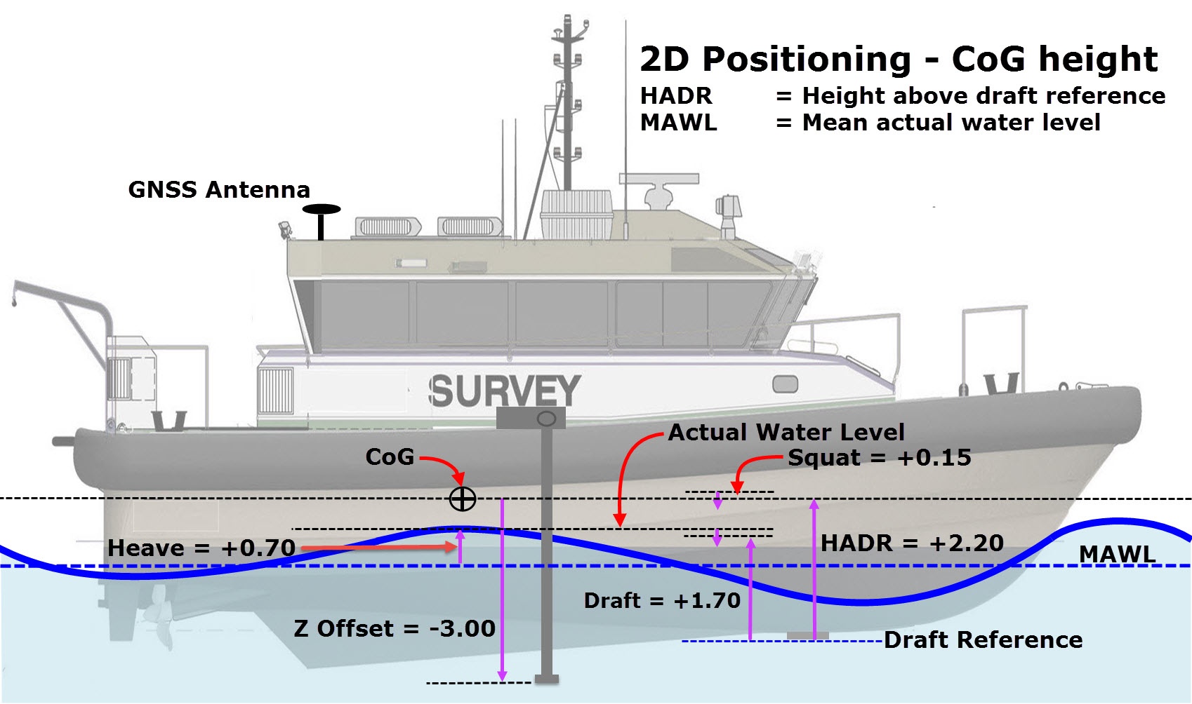
Draft: Depth as reported by a draft sensor or as measured.
Height Above Draft Reference (HADR): Height of the CoG above the zero reference point for draft measurement. This value is most meaningful to Qinsy users but less so for users importing data from other data formats.
Vessel
You can change the vessel type between Surface Vessel, ROV, AUV, Towed Fish, Link Tool and unknown/unsupported. Typically Qimera will detect the vessel type during import but this can sometimes fail to happen if the information needed to determine this is missing from incoming data files. In these instances, Qimera defaults to a Surface Vessel type. If you have an AUV, ROV, or Link Tool and your depths do not appear to be corrected for depth/pressure measurements, it is likely that the vessel type is incorrect. You can verify this in the vessel editor and make corrections if necessary.
Depth
Latency: Time latency of the reported measurements, this number is added to the requested time prior to any lookup of data from this sensor.
Offset: A static depth offset that is applied additively to the sensor records prior to being used in any computations.
Starboard/Forward/Up location: Sensor position relative to the CoG. These are used to establish the 3D position of the CoG.
Pressure
Latency: Time latency of the reported measurements, this number is added to the requested time prior to any lookup of data from this sensor.
Offset: A static pressure offset that is applied additively to the sensor records prior to being used in any computations.
Scale: A custom scaling factor that can be applied to convert to another pressure unit. Qimera stores pressure in bars.
Starboard/Forward/Up location: Sensor position relative to the CoG. These are used to establish the 3D position of the CoG.
Here is a graphic depicting values such as HADR, Draft, Draft Reference, Heave, and Squat:
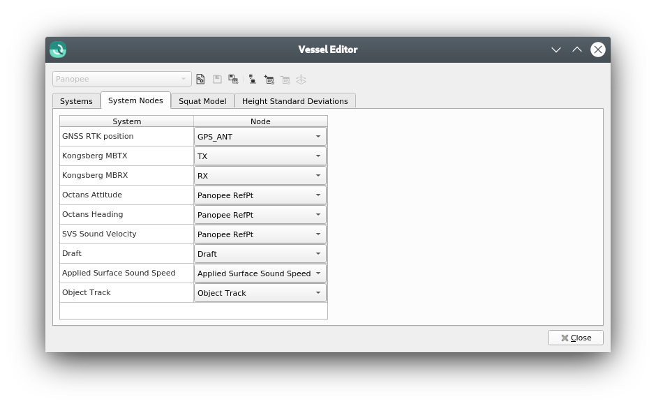
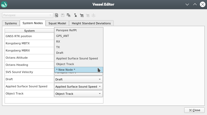
System Nodes Tab
For data from Qinsy DBs, a Systems Node tab will be visible:
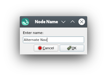
This tab allows viewing and editing of the nodes to which each system is linked. Optionally, a new node can also be created:
To move the node, change the offsets of the system linked to the new node.
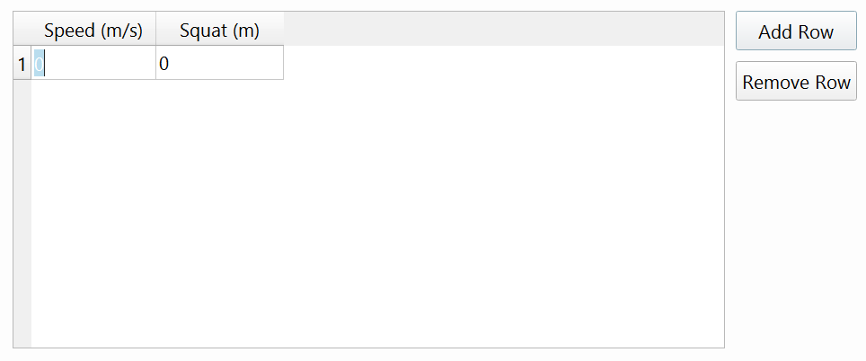
Squat Model Tab
The squat tab allows you to specify a speed dependent draft corrector lookup table that is used to correct the nominal draft as a function of vessel speed through the water. Currently, only Qinsy (.db) files can provide this information directly, users with other data formats will need to specify this manually by adding/removing rows using the Add Row and Remove Row buttons. Values appearing in the squat table can be edited. The squat correction is only used with vertical referencing methods "Tide" and "None".
Be aware that squat is positive if the vessel sits lower in the water due to the influence of the sea bottom. The units are the same as the project units.
Qimera does not currently support the following Qinsy Squat methods:
Froude
Barras
Polynomial
A Speed vs Squat table defined in the Qinsy DB setup will transfer over to Qimera successfully.
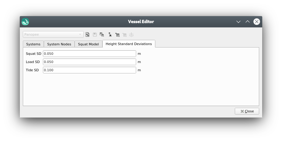
Height Standard Deviations Tab
The Height Standard Deviations tab allows for adjustment of the following standard deviations: