How-to Create a Mesh
This how-to briefly explains how a Fledermaus mesh can be created, used, and analyzed.
This functionality is only available in Fledermaus version 8.0, and described for 8.2 and above.
On this page:
Introduction
A mesh can represent more than one height value per cell, allowing better representation of a 3D object than a regular surface. If you inspect Figure 1a, there are some overhanging features on the wreck that are well represented Vs. Figure 1b a regular surface (that we could call 2.5D) of the same region of interest. It is apparent the detail would be lost by the one height value per cell limitation.
How is this achieved? Meshing in Fledermaus uses polygonal meshing techniques, which are created from a collection of vertices and triangles to make up a shape. The resulting mesh object will have a variable resolution (which means that the resolution of number of vertices and facets varies along the areas inspected), based on the point density, parameters set, and the shapes in the region of interest itself.
Due to these characteristics, a mesh can be a better option to model 3D objects that surfaces may have trouble representing truthfully, including data containing wrecks or vertical surfaces like a retaining wall.
For example, a Mesh vs a Surface of a wreck:
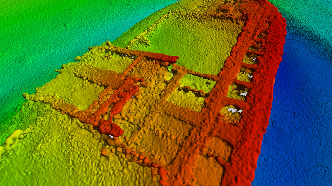
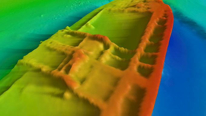
Figure 1b. 10cm surface - Brest Wrecks dataset
Creating a Mesh
A mesh is created from point files, including file types such as .qpd's and .points files.
There are a a few ways that you can begin the meshing process. You can create from previously imported points files, or create upon import of external points files.
However this how-to will focus on the steps to create a mesh from previously imported files, that are already part of a scene.
Step-by-step
Step 1: Determine which files you are using and select them.
With the imported point files in the scene, you will need to select the specific files that you would to create a mesh from. Meshing is an intensive operation, we do not recommend that you run full datasets. First select a region of interest to try parameters and ensure you have a selection around the desired area in the scene. For more information on importing data in Fledermaus 8, please visit Fledermaus File Menu or Fledermaus Import Menu.
Step 2: Open the Meshing Wizard.
From the Operations menu in the Objects dock:
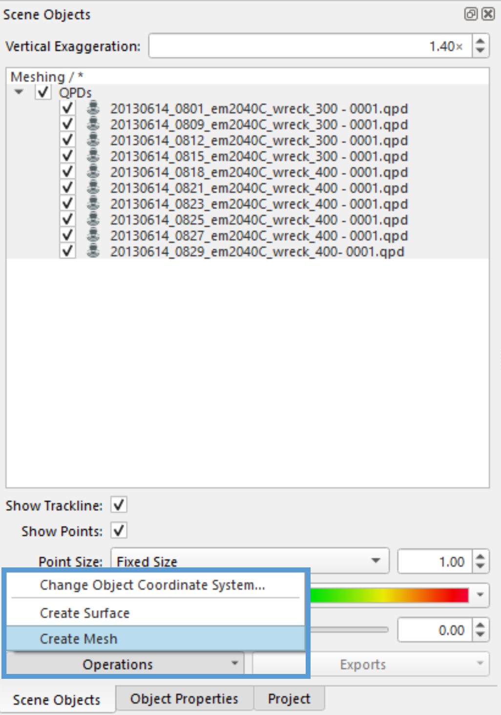
Figure 3. Operations Menu - Create Mesh
You can also access the Operations > Create Mesh wizard through the right click menu options on the selected files, as shown in Figure 4:
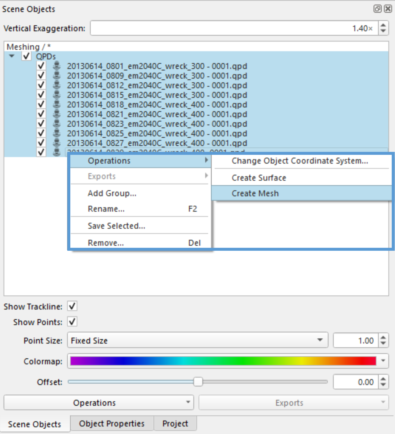
Figure 4. Right click menu options, guided to Operations > Create Mesh.
Step 3: Set up required parameters.
When you first open the meshing wizard, select the type of algorithm that you are going to use from the Mesh Creation Algorithm drop down menu. There are two options here: Poisson Surface Reconstruction as seen in Figures 5 and the Delauney Triangulation depicted with parameters in Figure 6, and each option will give you a different set of parameters to establish. Below some example parameters that you can try if you use the sample dataset. You can find the detailed explanation of the parameters for the meshing algorithms in Fledermaus Create Mesh Wizard which is part of the Fledermaus 8.x reference manual.
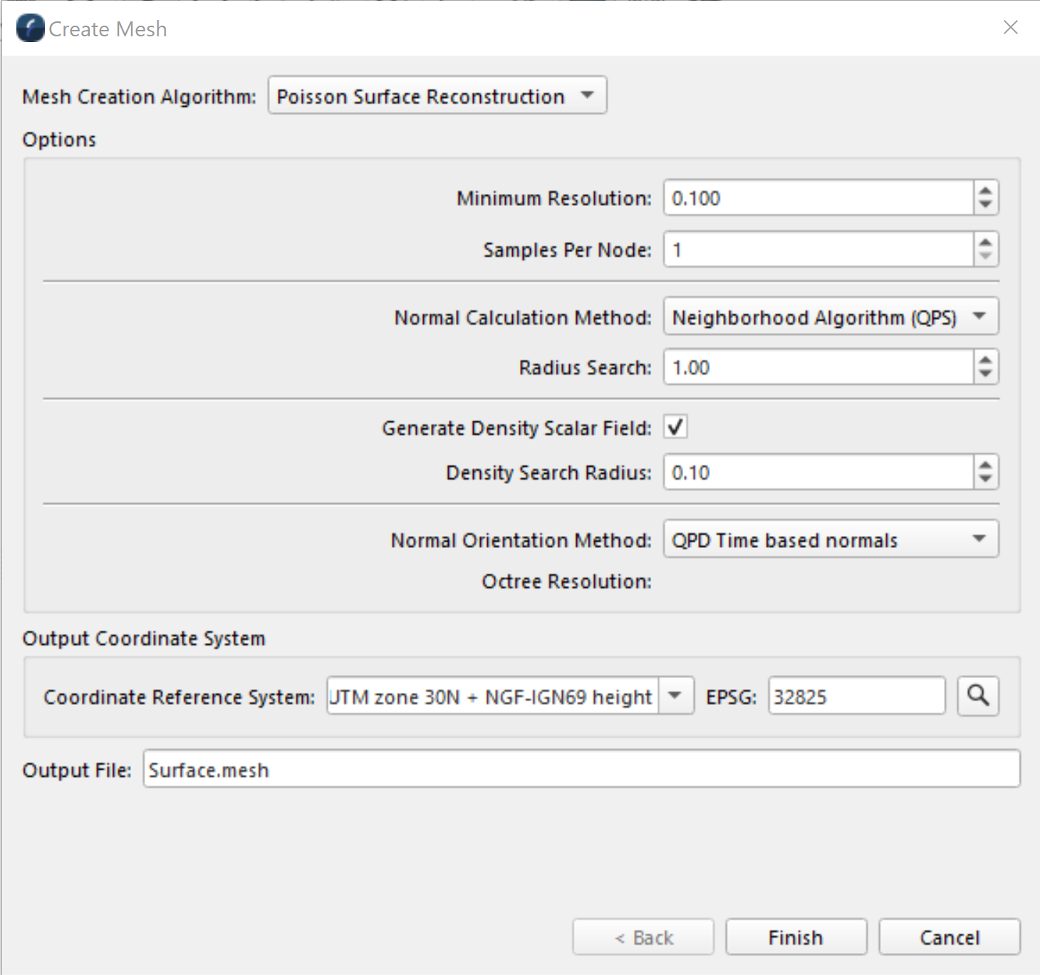
Figure 5. Create Mesh Wizard - Poisson Surface Reconstruction
By default this algorithm will be selected when the wizard is first opened. It is the true 3D option, and allows more for more customization of the parameters used. However the trade off here is that this method often has longer processing times, and higher hardware requirements.
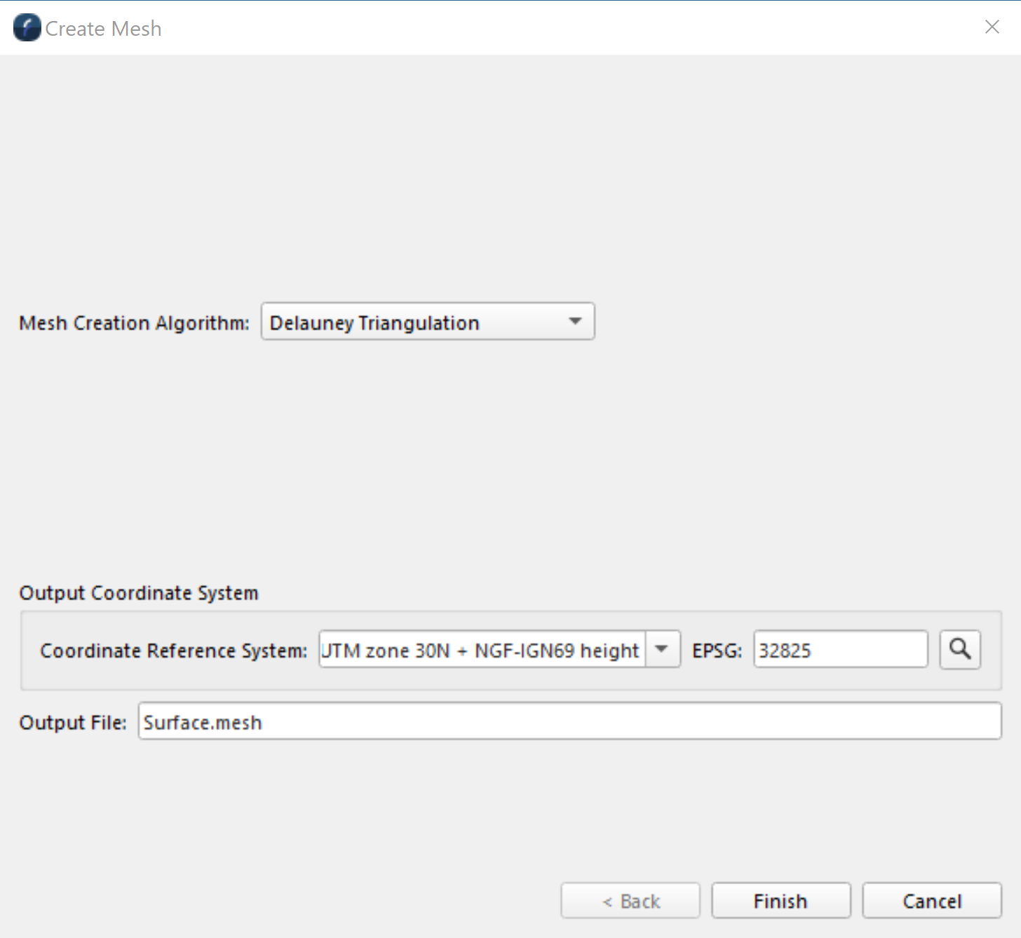
Figure 6. Create Mesh Wizard - Delauney Triangulation
This algorithm produces a surface which does not represent objects in 3D, but does represent steep slopes and 3D objects better than a regular 2.5D surface. This option may have fewer parameters to customize, but is a much faster and less demanding process
Step 4: Create your mesh.
Select 'Finish' once you are happy with the parameters to be set. Fledermaus will then proceed to create a mesh. Depending on the parameters chosen by user you could have an end result as depicted in Figure 7.
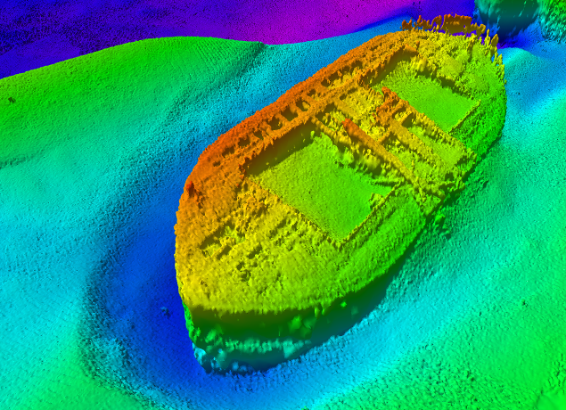
Figure 7. Resulting 5cm mesh - Brest wrecks dataset
To keep in mind:
You may need to go through a couple of iterations to find the best parameters, it will depend on your dataset.
The meshing process is a computing intensive process with high memory requirements, it will require time and memory available in the computer. Therefore in many cases a small selection containing a feature of interest may be all that is needed, paired together with a regular 2.5D surface to model a general seafloor around the feature.
Step 5: Working with the resulting mesh.
Once a mesh object is part of the scene, it will be displayed in the Fledermaus Scene Objects Dock with all other objects in the scene.
Aside from the ability to change the object coordinate system of your mesh, there are two mesh specific operations that can be done: clip mesh (a) and slice mesh (b). These can be found in the Operations drop down menu on the object docks.
a. Clip Mesh
The Mesh Clipping dialog, as seen in Figure 8 below, can be used to clip the selected mesh according to the sounding density along its surface.

Figure 8. Mesh Clipping Range dialog
As seen in Figure 8 above, by default the minimum sounding density is set to 1, so as to hide areas that have 1 or fewer soundings in them.
For example, Figures 9a-c show this funtionality, comparing the default range (Figure 9a) to a reduced range (Figure 9b):

Figure 9a. Default Range
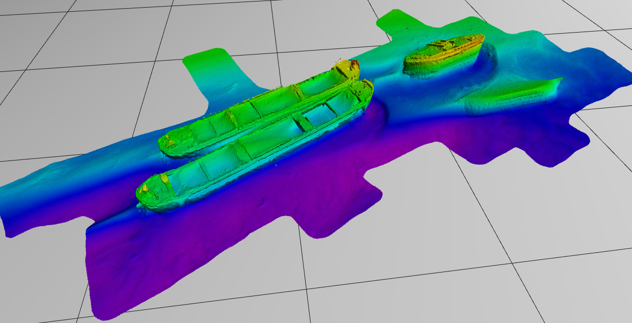
Figure 9b. Reduced Range
Detailed information on the mesh clipping parameters can be found here Fledermaus Mesh Clipping Dialog.
b. Slice mesh
The Mesh Slicer dialog, as seen in Figure 10 below, allows the user to slice the selected terrain mesh on X,Y and/or Z axis.
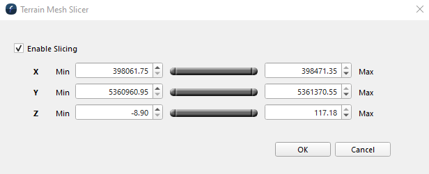
Figure 10. Terrain Mesh Slicer Dialog
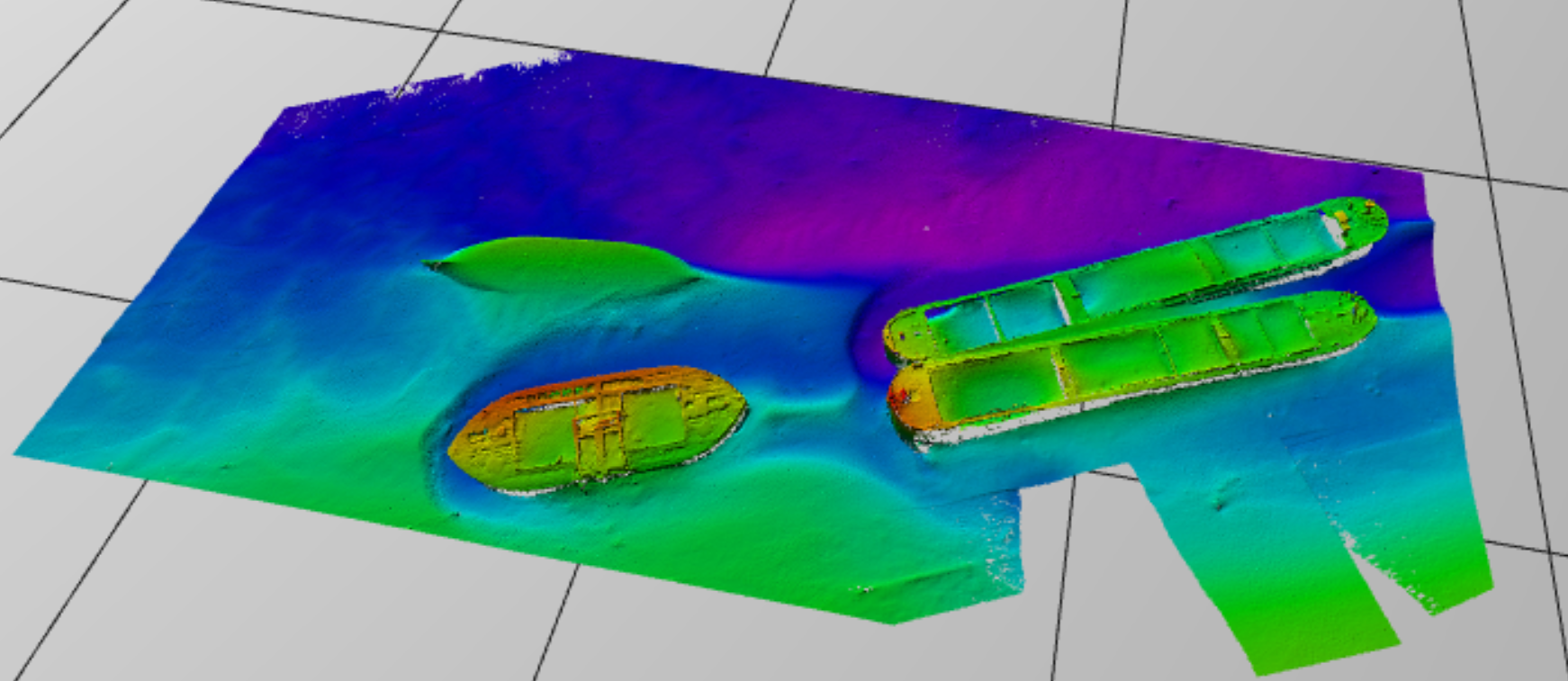
For example, in Figure 11a is the mesh before slicing, and in Figure 11b is the mesh after slicing:
Figure 11a. Mesh before slicing
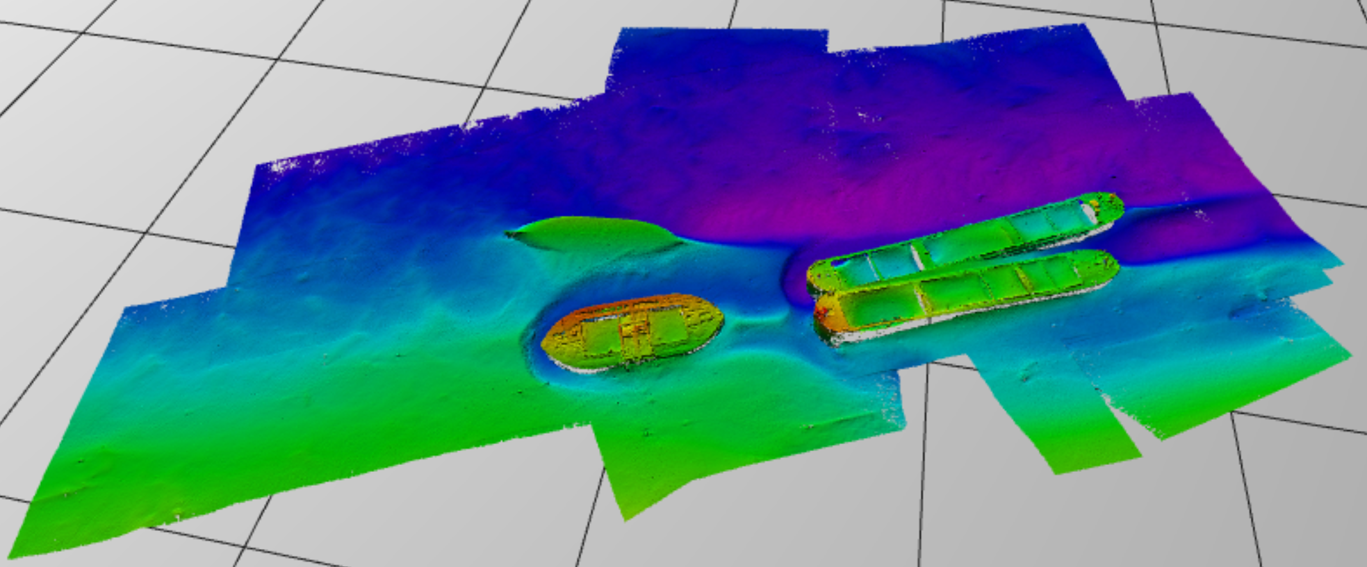
Figure 11b. Mesh after slicing
For more information on the Slice mesh window please visit Fledermaus Mesh Slicer Dialog
Return to:
