
Driver to decode data from SBG Ekinox and Ellipse systems with a binary log.
Driver is available as:
-
Position Navigation System
-
Gyro Compass
-
Pitch Roll Heave sensor
-
Time Synchronization system
-
Acceleration, Velocity & Rotation Rate
-
Miscellaneous System
Driver Information
Click to expand...
System Configuration
Click to expand...
The Ekinox units support multiple interface types (serial, network, CAN, Logic I/O).
Qinsy supports the following interfaces:
-
Serial
-
Network
-
TCP
-
UDP
-
Time Synchronization
Testing has shown that the TCP interface type is not suitable for the Time Synchronization system as there is too much "jitter" on this interface.
The IP address can be found either on the SBG unit or in the sbgCenter.
The first screen which will appear can be seen below. Here you can still see the system interfacing, make sure that you select the correct view which applies to your type of survey.
Status information can be found on the front page as well including:
-
System connection
-
Alignment
-
Timing/clock
-
GNSS mode
-
and various other types of information
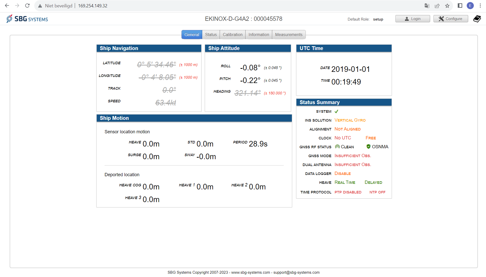
Manuals can be found on their website https://support.sbg-systems.com/
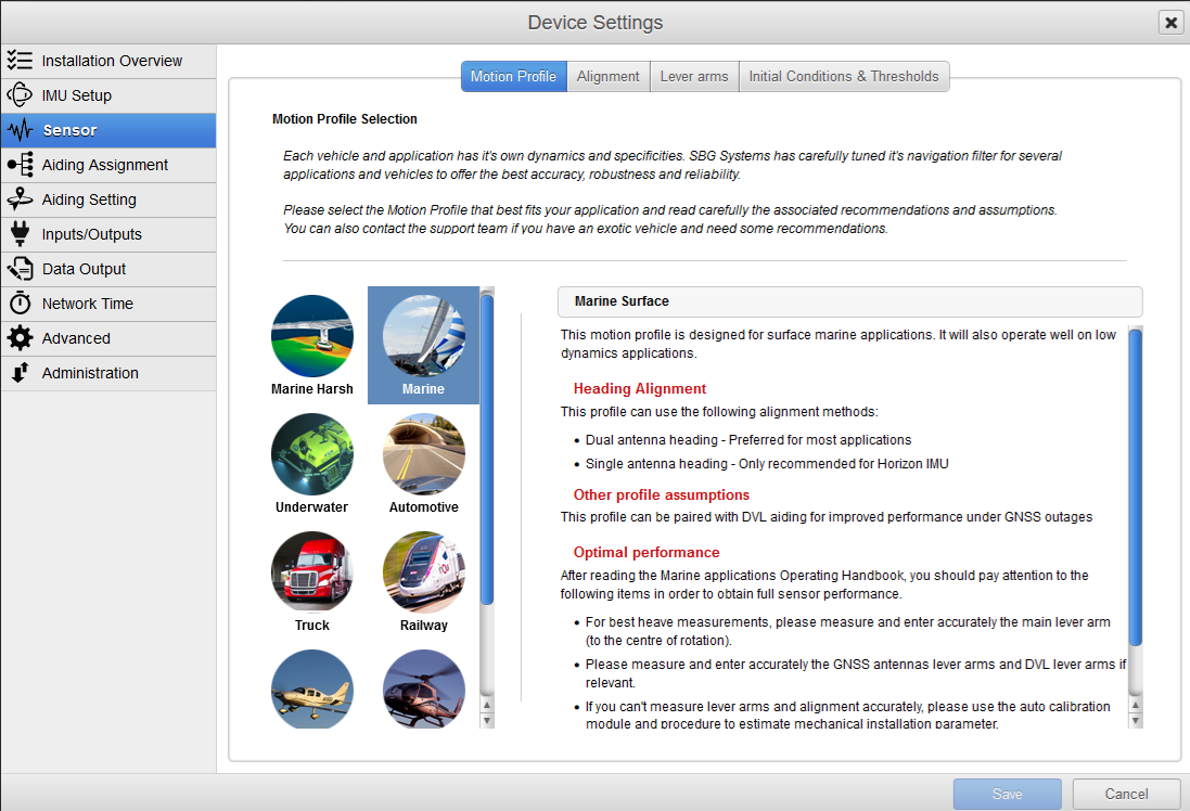
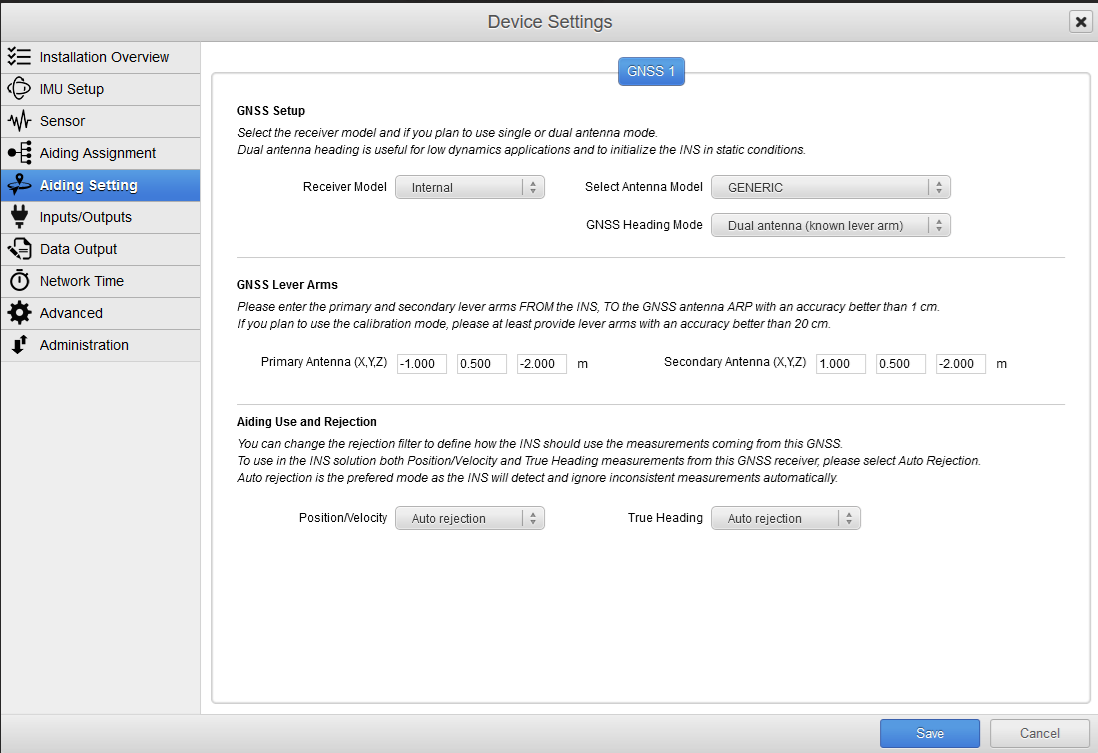
Orientation and offsets
|
|
|
Select the Motion profile:
|
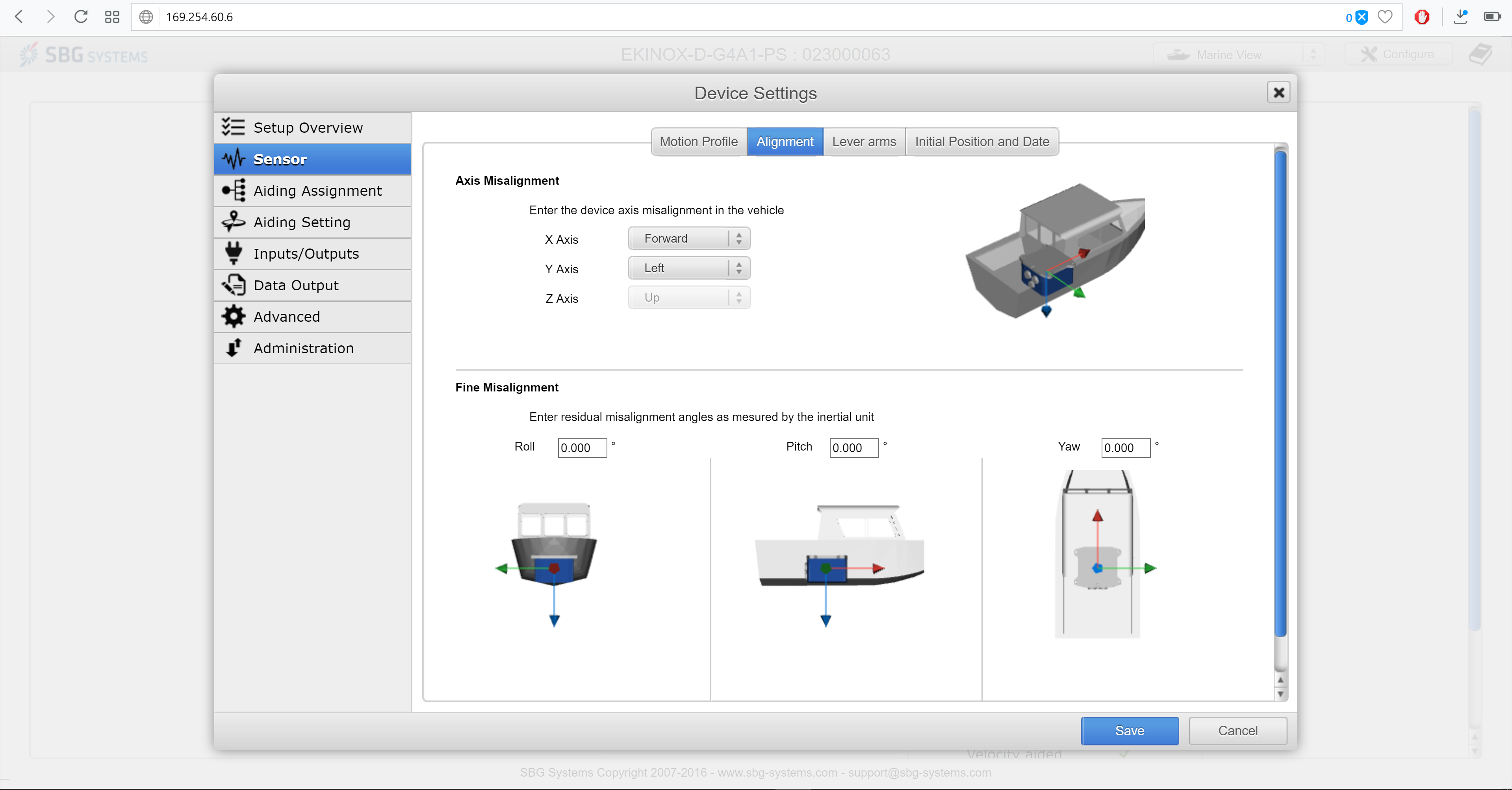
Select the correct Alignment:
|
|
|
|
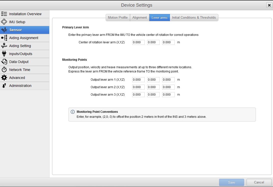
Enter the Lever arms, by keeping the alignments in mind (X, posititive forward/Y, positive starboard/Z, positive downwards) |
Make sure that you enter the location of the Antennas as well. You can also select if the Position, Velocity and True should be used. |
|
|
|
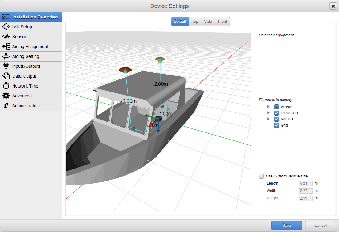
3D environment to check your setup |
|
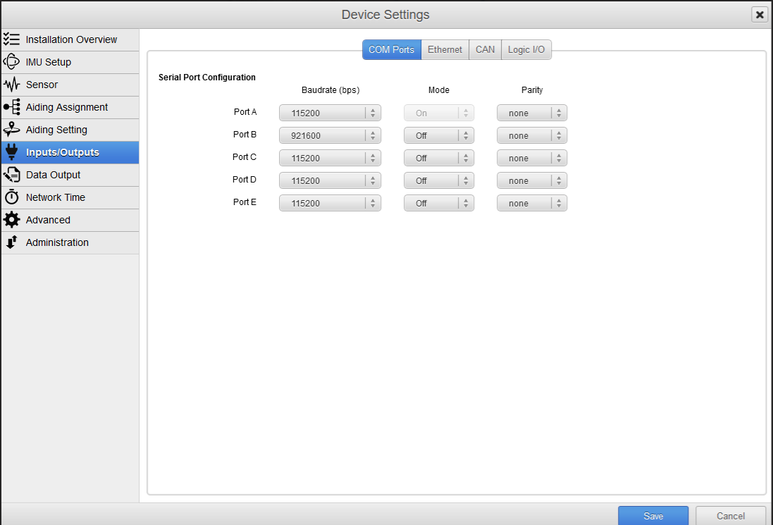
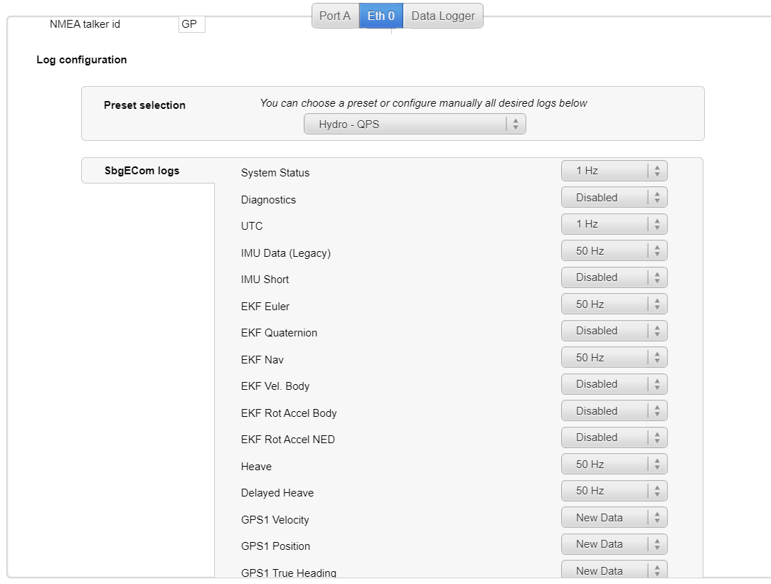
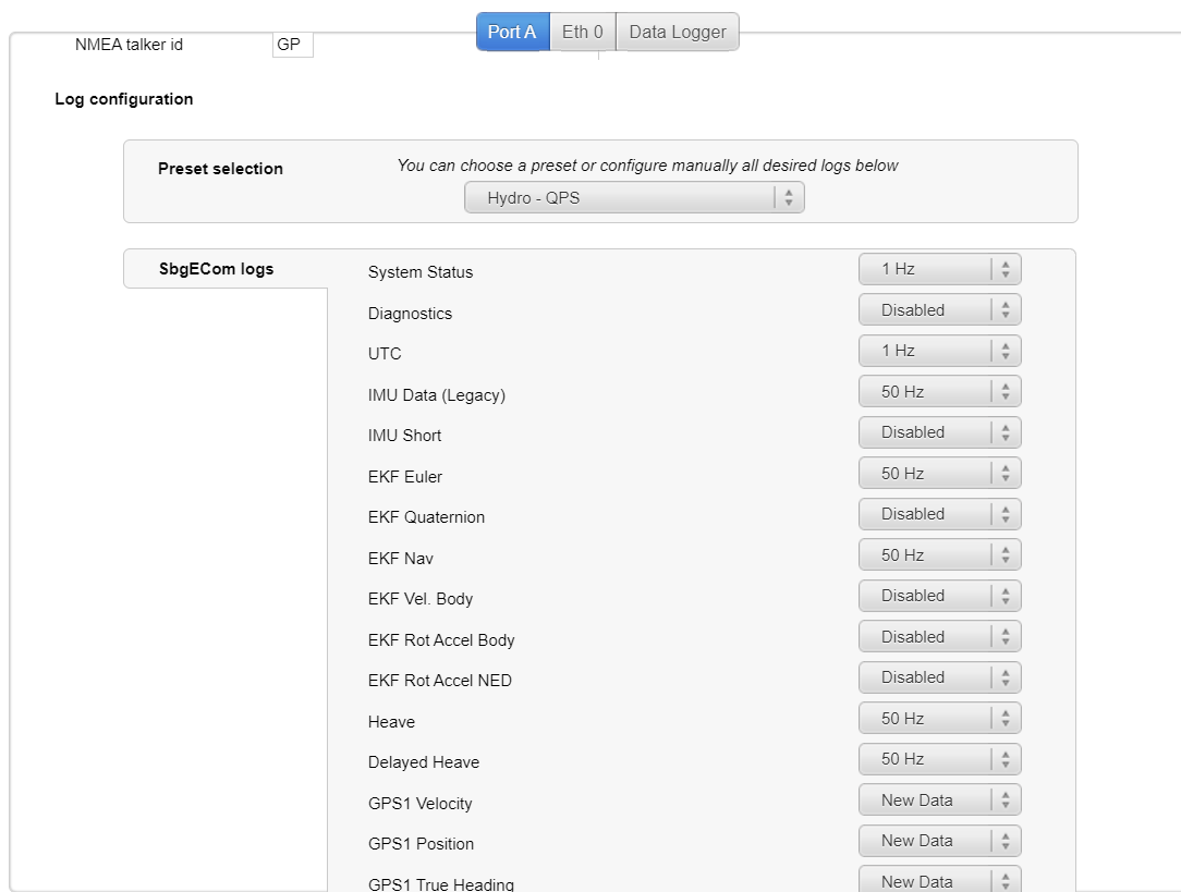
In order to use either of these interfaces, they must be enabled through the embedded web server.
Here interface parameters (e.g. port number, IP-address, baud rate, etc.) can be set:
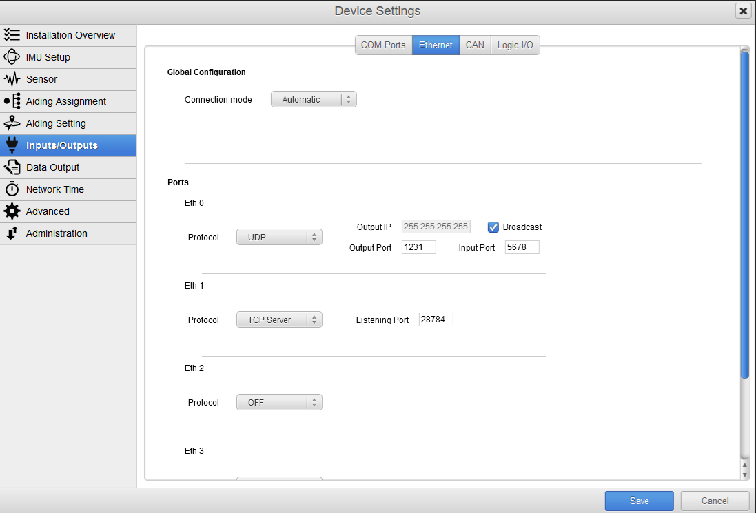
|
|
The user must also configure which messages the unit should send out on each interface. Also select the correct Output Monitoring Point.
The status message is a special message because it contains status information of many of the other message types. As such, it is vital for Qinsy to determine the quality of the data from the unit and must always be enabled.
The UTC message is another special message that is mandatory when the message time stamp is decoded from the message (see DM-0378#Driver Selection). Which Qinsy systems use which messages is described in detail in the remainder of this document.
The table below summarizes all the logs that this driver can decode.
|
Message type |
Mandatory |
Contains |
|---|---|---|
|
System status |
Yes |
Validity information of other messages |
|
IMU data (Legacy) |
No |
Acceleration and Rate-of-turn |
|
EKF_EULER |
No |
Roll, pitch and heading |
|
EKF_NAV |
No |
Velocity and Position |
|
Heave |
No |
Heave, Acceleration and Velocity |
|
Delayed heave |
No |
Delayed heave Available with Ekinox only |
|
UTC |
If UTC driver is used |
UTC time |
|
GPS(1-2)_VEL |
No |
Velocity |
|
GPS(1-2)_POS |
No |
Position |
|
GPS(1-2)_HDT |
No |
Heading |
|
ODO_VEL |
No |
Velocity |
Output Rate
The Ekinox units are capable of outputting data at high frequencies (up to 200Hz). Due to limited buffer space, it is advised to not select an output rate higher than 50Hz this is preset by QPS (see preset selection).
|
|
Note
The Ellipse Series and Ellipse 2 Series do not support the online interfacing. Please refer to the sbgCenter.
SBG Center
Please connect the SBG unit to the computer via Ethernet or serial.
Open the sbgCenter (downloaded app):
-
Check in the Settings to which kind of unit you are connecting:
-
Serial for the Ellips
-
Ethernet for the Ekinox unit
-
-
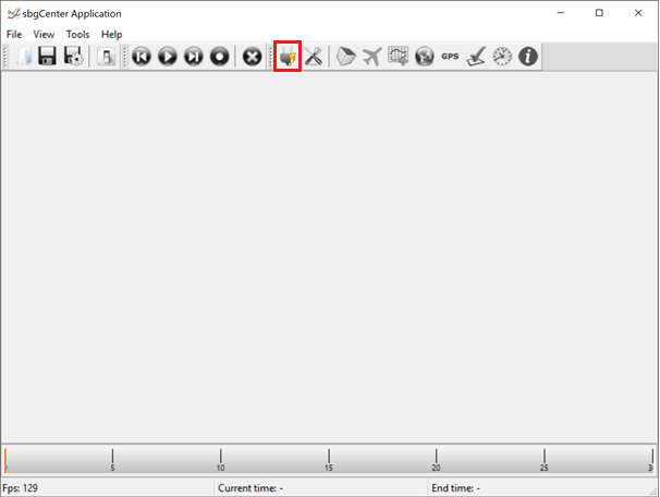
Connect your system via the Connect icon:
-
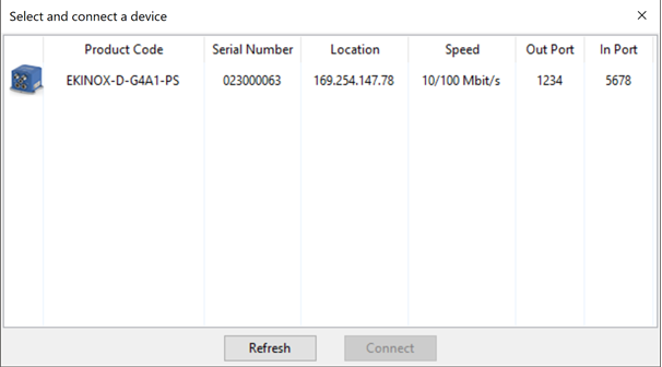
The 'Select and connect a device windows' opens
-
Click on Refresh to find the unit connected to the computer
-
In case an Ethernet is connected, the IP location can be found here as well (this will help to connect via the web browser)
-
Select the device and connect.
-
|
|
SBG information
Device information
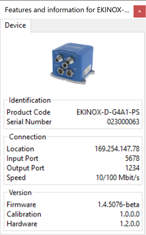
|
|
|
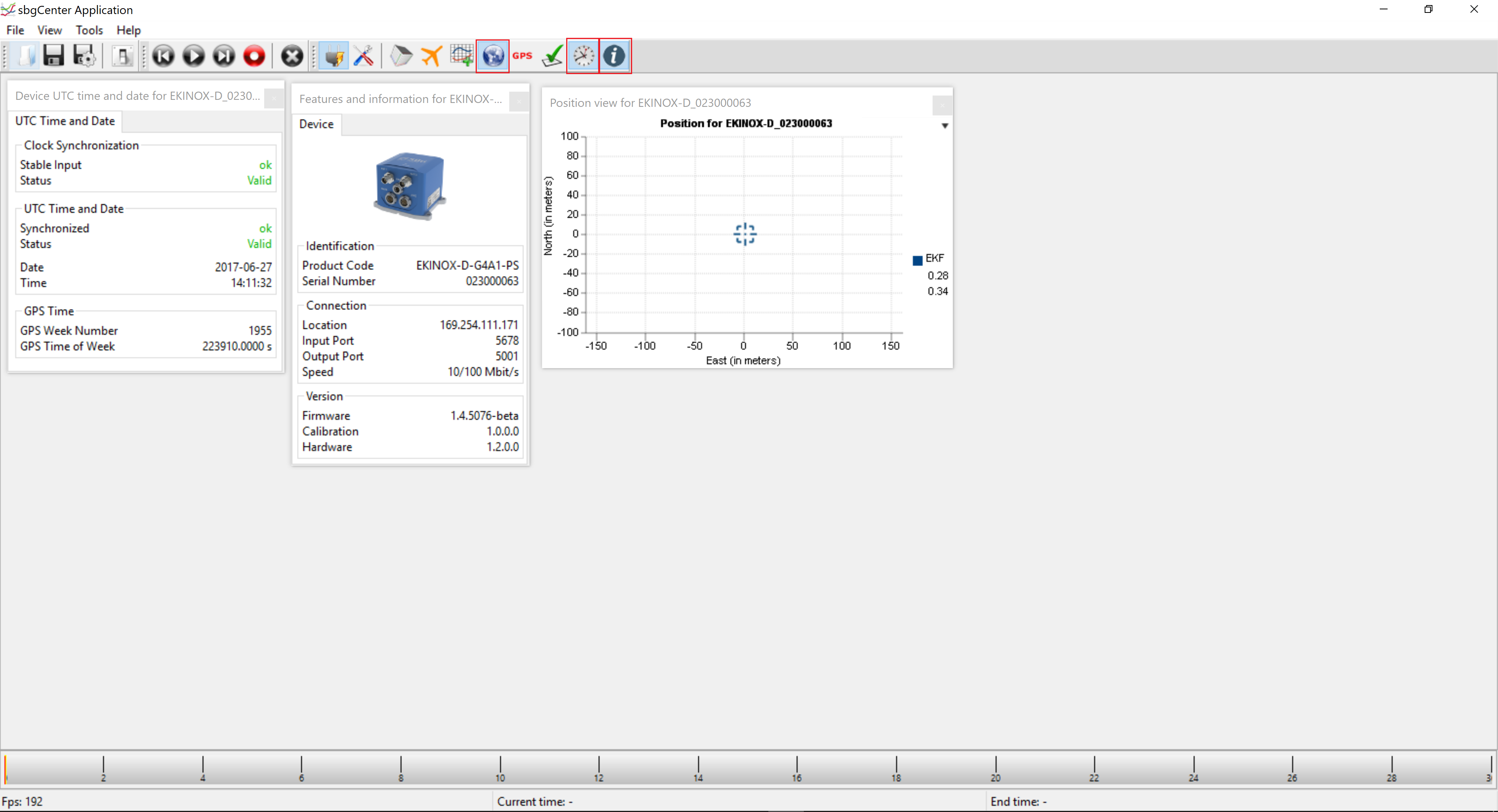
Device information displayed:
|
Device UTC time and Date for Ekinox D
Position view for Ekinox D
|
Device status
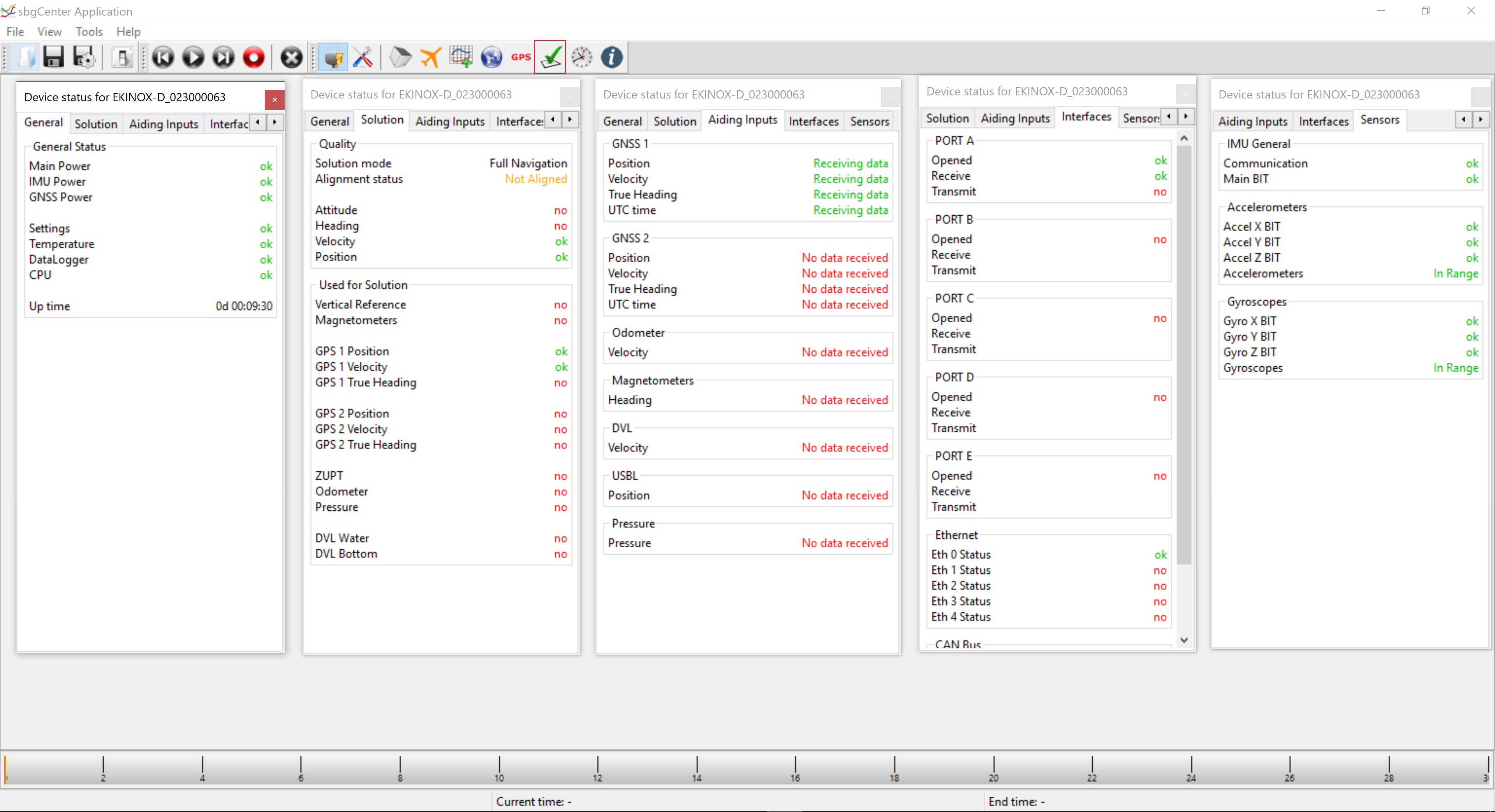
|
|
General:
Solution:
Aiding Inputs:
Interfaces:
Sensors:
|
Once all the above is checked and correctly received, the following information can be displayed as well:
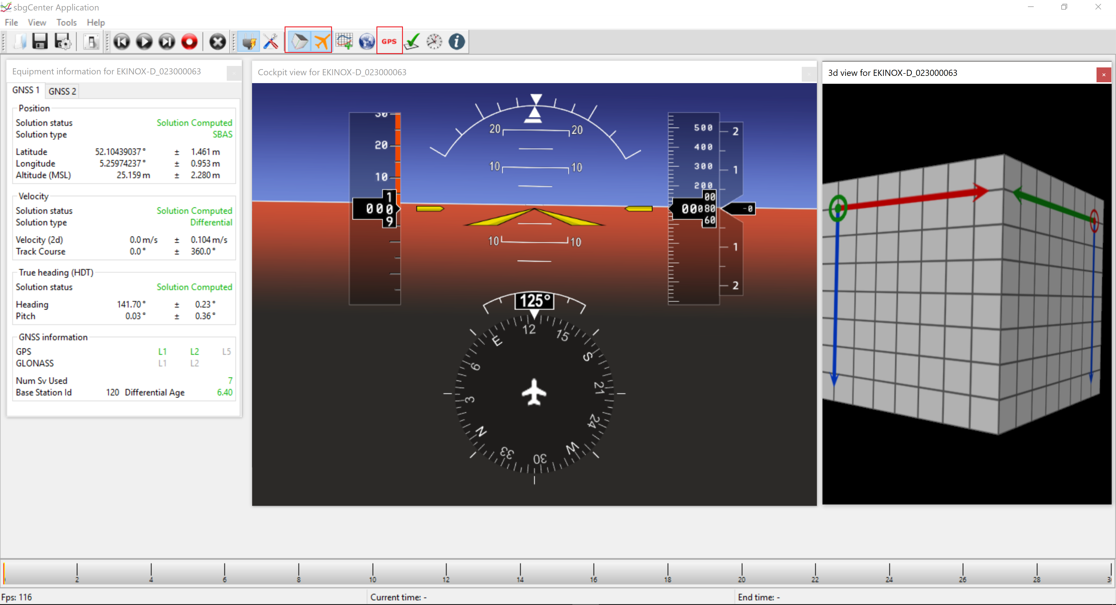
|
|
|
Equipment Information Position:
Velocity:
True Heading:
GNSS information:
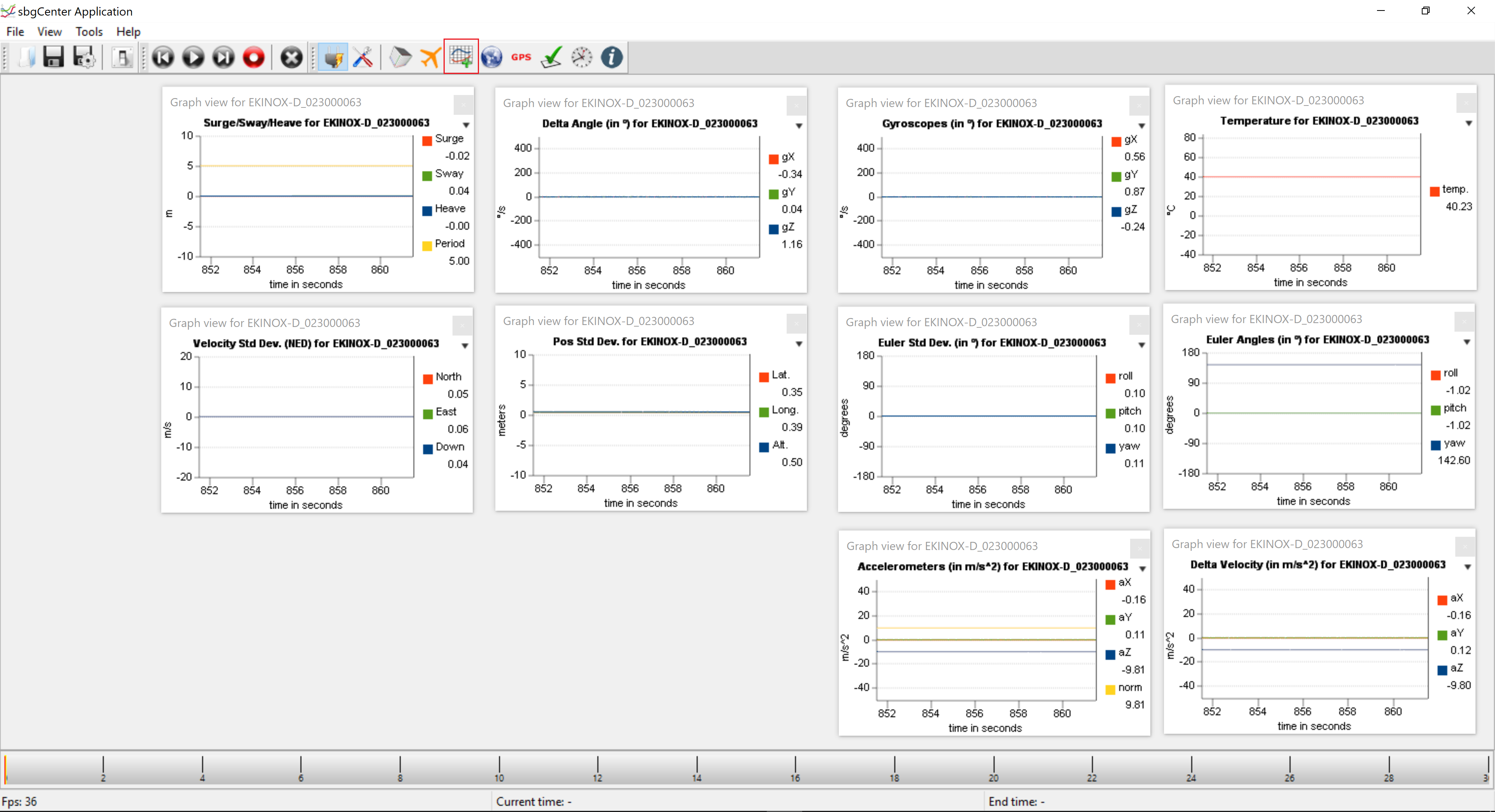
3D view
|
Various kinds of graphs can be displayed |
Note
Please note that the sbgCenter can be used for troubleshooting, however the sbgCenter should be closed when using Qinsy, as it occupies the SBG unit.
Interfacing Notes
Qinsy Database Setup
For each system, the user will have to choose from a number of drivers based on which interface is used (TCP/UDP/Serial) and whether the incoming message is time stamped with the UTC time in the message, or at the time of arrival.
-
-
Position
-
-
-
Heading
-
-
-
Motion
-
Pitch
-
Roll
-
Heave (Real Time)
-
-
-
-
Time
-
-
Acceleration, Velocity & Rotation Rate
-
Acceleration
-
Velocity
-
Rotation rate
-
-
-
Metadata
-
Delayed Heave
-
The table below shows which driver to choose for each interface-UTC combination. The exact name of the driver differs per system, this is indicated in the table by <system type> which should be replaced by a system specific text.
(F.i. "Network (TCP) SBG Systems (R-P-H) (UTC) " or "Network (TCP) SBG Systems Heading (UTC)").
|
Interface |
Use UTC time in message |
Driver |
|---|---|---|
|
Serial |
Yes |
SBG Systems <system type> (UTC) |
|
No |
SBG Systems <system type> |
|
|
TCP |
Yes |
Network (TCP) - SBG Systems <system type> (UTC) |
|
No |
Network (TCP) - SBG Systems <system type> |
|
|
UDP |
Yes |
Network (UDP) - SBG Systems <system type> (UTC) |
|
No |
Network (UDP) - SBG Systems <system type> |
Note
If the SBG system is used without a GPS (either internal or external), the user should always choose the non-UTC driver as the GPS's UTC message is used to calculate other messages' time tags.
Note
If UTC drivers are used, make sure that the unit is configured to output the UTC_TIME log. This log is necessary to calculate the UTC time for other messages.
If UTC drivers are chosen and the UTC_TIME log is not received, the driver will not function properly!
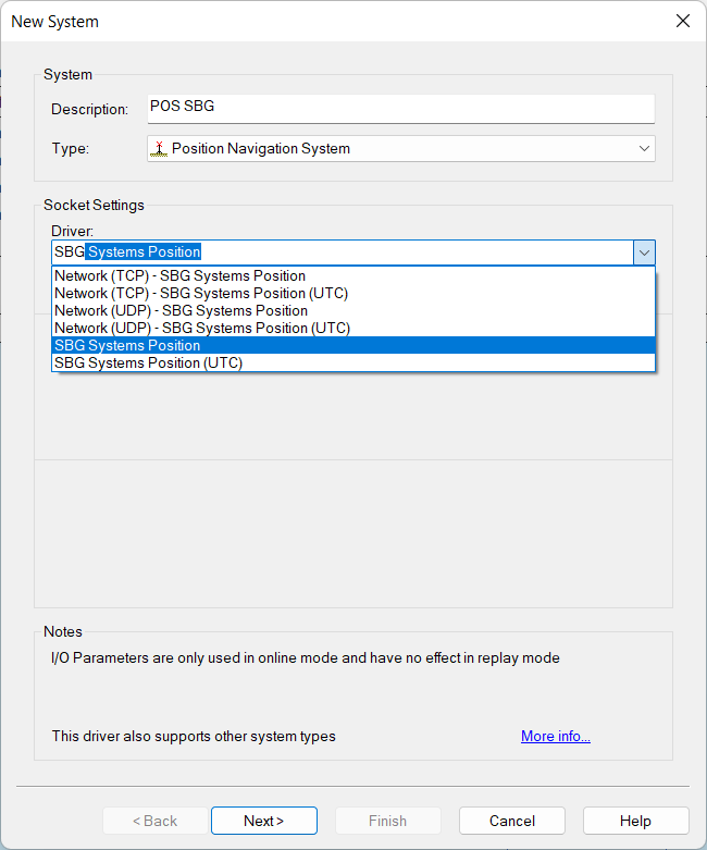
Position Navigation System
Click to expand...
In order to decode a position from the Ekinox:
-
Add a Position Navigation System to your template and select the appropriate Driver Selection Ekinox driver
-
Select the port and/or IP address of the Ekinox unit
-
Select for Horizontal and Vertical datum the datum of your GNSS receiver (depends on your correction source)
-
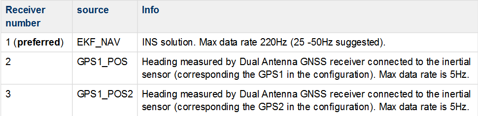
Position information can be decoded from EKF_NAV, GPS1_POS or GPS2_POS log.
Which log is used, is based on the selected receiver number in Database Setup: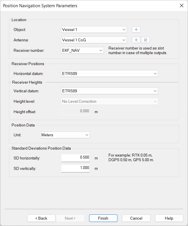
|
Receiver number |
source |
Info |
|---|---|---|
|
EKF_NAV (preferred) |
EKF_NAV |
INS solution. Max data rate 200Hz (25 -50Hz suggested). |
|
GPS1 |
GPS1_POS |
This is the position out from the GNSS receiver defines as GPS1 in the configuration of the sensor. It can be used as backup / secondary, and max output rate is 5 Hz. No solution during GNSS drop out. Also heading measured by Dual Antenna GNSS receiver connected to the inertial sensor (corresponding the GPS1 in the configuration). Max data rate is 5Hz. |
|
GPS2 |
GPS2_POS |
This is the position out from the GNSS receiver defines as GPS2 in the configuration of the sensor. It can be used as backup / secondary, and max output rate is 5 Hz. No solution during GNSS drop out. Also heading measured by Dual Antenna GNSS receiver connected to the inertial sensor (corresponding the GPS2 in the configuration). Max data rate is 5Hz. |
Position set up before 9.7
Changes in the set up have been made since 9.7.1. In case the user is using an older version then this, the set up is still the same but the receiver number must be set as an integer:
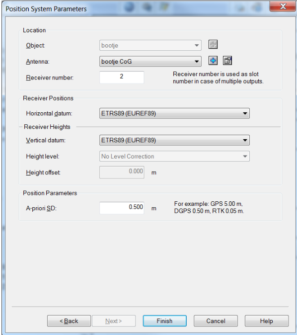
Where:
Old receiver numbers are still compatible but when inside the configuration of the driver the receiver number field needs to be updated.
Quality (Qinsy 9.7 and newer)
The possible values of the quality indicator (displayed as "solution mode" in the Positioning System Display) depend on which log is used for the system.
If the position is decoded from the NAV log, the status is decoded from the POSITION_VALID bit in the STATUS log.
If either GPS1 or GPS2 is used to decode the position, the quality is decoded from the GPS_POS_STATUS field in the LOG_GPSx_POS log in the following way:
-
If SBG_ECOM_GPS_POS_STATUS is equal to SBG_ECOM_POS_SOL_COMPUTED (a valid position has been computed), the variable SBG_ECOM_GPS_POS_TYPE is returned.
-
If SBG_ECOM_GPS_POS_STATUS is not equal to SBG_ECOM_POS_SOL_COMPUTED, SBG_ECOM_GPS_POS_STATUS multiplied by -1 is returned.
This leads to the following possible values for the position quality:
Quality flag for the NAV is a combination of the NAV and GPS1 values:
|
Log |
Possible values |
INS/GPS status combination |
Value meaning |
|---|---|---|---|
|
NAV |
-1 |
INS invalid (-1) |
INS status invalid. Position data is unreliable (Position error > 10m) |
|
|
1 |
INS valid (1) & GPS(-3 trough 1) |
An unknown solution type has been computed, or GPS1’s value is lower than 1. |
|
|
2 |
INS valid (1) & GPS(2) |
Single point solution position. |
|
|
3 |
INS valid (1) & GPS(3) |
Standard Pseudo range Differential Solution. |
|
|
4 |
INS valid (1) & GPS(4) |
SBAS satellite used for differential corrections. |
|
|
5 |
INS valid (1) & GPS(5) |
Omnistar VBS Position (L1 sub-meter). |
|
|
6 |
INS valid (1) & GPS(6) |
Floating RTK ambiguity solution (20 cms RTK). |
|
|
7 |
INS valid (1) & GPS(7) |
Integer RTK ambiguity solution (2 cms RTK). |
|
|
8 |
INS valid (1) & GPS(8) |
Precise Point Positioning with float ambiguities. |
|
|
9 |
INS valid (1) & GPS(9) |
Precise Point Positioning with fixed ambiguities. |
|
|
10 |
INS valid (1) & GPS(10) |
Fixed location solution position. |
Quality flag values based on the combination of NAV and GPS solution values.
|
Solution mode: |
GPS Valid: |
GPS Invalid: |
|
NAV Valid: |
GPS |
1 |
|
NAV Invalid: |
-1 |
-1 |
Quality flag for GPS1/GPS2
|
Log |
Possible values |
Value meaning |
|---|---|---|
|
GPS1/GPS2 |
-1 |
Not enough valid SVs to compute a solution. |
|
-2 |
An internal error has occurred. |
|
|
-3 |
The height limit has been exceeded. |
|
|
0 |
No valid solution available. |
|
|
1 |
An unknown solution type has been computed. |
|
|
2 |
Single point solution position. |
|
|
3 |
Standard Pseudorange Differential Solution. |
|
|
4 |
SBAS satellite used for differential corrections. |
|
|
5 |
Omnistar VBS Position (L1 sub-meter). |
|
|
6 |
Floating RTK ambiguity solution (20 cms RTK). |
|
|
7 |
Integer RTK ambiguity solution (2 cms RTK). |
|
|
8 |
Precise Point Positioning with float ambiguities. |
|
|
9 |
Precise Point Positioning with fixed ambiguities. |
|
|
10 |
Fixed location solution position. |
Gyro
Click to expand...
In order to decode a heading from the Ekinox:
-
Add a Gyro Compass System to your template and select the appropriate Ekinox driver
-
Select the port and/or IP address of the Ekinox unit
-
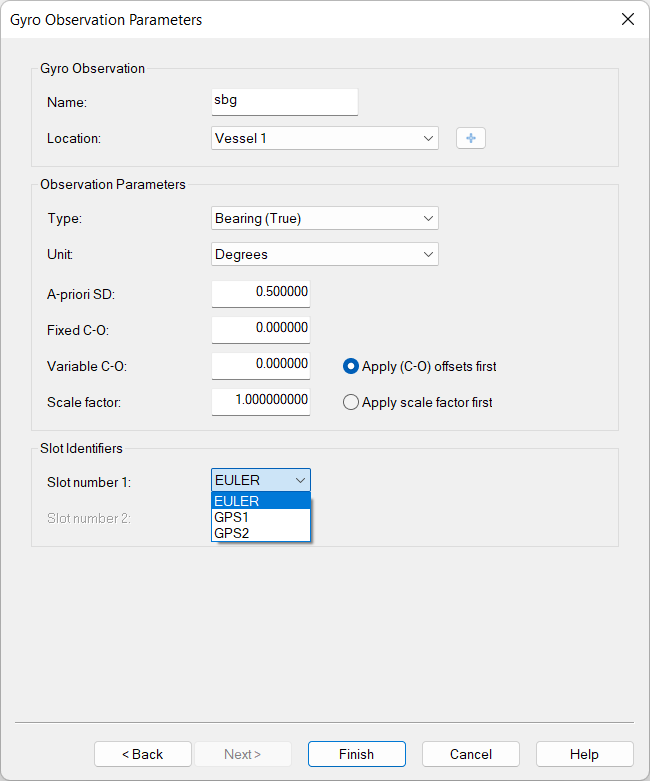
Select Type: bearing, Unit: degrees
-
Heading data can be decoded from EKF_EULER, GPS1_HDT or GPS2_HDT log.
Which log is used is based on the slot value in Database Setup:
|
Slot value |
Log |
Info |
|---|---|---|
|
EULER (preferred) |
EKF_EULER |
INS solution. Max data rate 200Hz (25 -50Hz suggested). Will continue with outputting solution during GNSS drop out. |
|
GPS1 |
GPS1_HDT |
Heading measured by Dual Antenna GNSS receiver connected to the inertial sensor (corresponding the GPS1 in the configuration). Max data rate is 5Hz. (no solution during GPS drop-out) |
|
GPS2 |
GPS2_HDT |
Heading measured by Dual Antenna GNSS receiver connected to the inertial sensor (corresponding the GPS2 in the configuration). Max data rate is 5Hz. (no solution during GPS drop-out) |
Quality
The possible values of the quality indicator (displayed as "solution mode" in the Positioning System Display) depend on which log is used for the system:
-
If the EULER log is used to decode heading, the quality of the data is decoded from the SBG_ECOM_SOL_HEADING_VALID bit in the SOLUTION_STATUS field of the LOG_STATUS log.
-
If either of the GPSx_HDT logs is used to decode the heading, the quality is decoded from the GPS_HDT_STATUS field in the log.
This leads to the following possible values for the heading quality:
|
Log |
Possible values |
Value meaning |
|---|---|---|
|
EULER |
1 |
Heading data is reliable (Heading error < 1°) |
|
-1 |
Heading data is not reliable (Heading error >= 1°) |
|
|
GPS1/GPS2 |
1 |
A valid solution has been computed. |
|
-1 |
Not enough valid SV to compute a solution. |
|
|
-2 |
An internal error has occurred. |
|
|
-3 |
The height limit has been exceeded. |
In order to decode a heading from the Ekinox:
-
Add a "Time Synchronization" system to your template and select the appropriate Ekinox driver
Warning
Do not use the TCP driver for a Time Synchronization system. During testing we found out that there is too much "jitter" on this interface to decode the UTC time properly.
-
Select the port and/or IP address of the Ekinox unit
-
On the next page enable the use of your Time Synchronization adapter, or leave it disabled if you do not have a Time Synchronization pulse interfaced to Qinsy.
Normally the use of a Time Synchronization adapter is highly recommended, but notice that in a setup where all other systems are already UTC time-tagged from an external time source (GNSS receiver), there is no need for Qinsy to use a Time Synchronization adapter.
Info
Ekinox units with an internal GPS provide the possibility to output the Time Synchronization (PPS) pulse on an output port.
Please refer to the Ekinox user manual for additional information.
Warning
If a time synchronization system is used, the unit must be configured to output a UTC_TIME log.
For the best performance, set the output rate to 1Hz.
Pitch, Roll and Heave
Warning
Ekinox does not pack pitch, roll and heave into a single log.
-
Pitch and roll are packed in the EULER log
-
Heave is packed in one of the SHIP_MOTION logs.
The calculation times of these two logs are not synchronized.
As a result, the driver cannot decode pitch, roll and heave for one single point in time.
Please read the info underneath carefully.
There are two options to interface the system with Qinsy:
-
Single Pitch, Roll and Heave system
-
PRO
-
Reprocessing in Qimera will give you the same result as Qinsy.
-
You only have to add one Pitch/Roll/Heave system to your setup.
-
-
CON
-
The Heave might be not be timestamped accurately enough.
The resulting VRU observation will be timestamped with the time the roll and pitch were calculated. The observation will contain the heave of the SHIP_MOTION_x log received after the EULER log that was the source of the roll and pitch. In this scenario, the heave in the observation may be calculated at a different time than the pitch and roll. If the EULER log and the SHIP_MOTION_x log have the same output rate, the maximum time difference between the pitch/roll and the heave is equal to 1 over the output rate in seconds. This means that if the motion data is outputted at:
10Hz → max time difference of 0.1 sec;
40Hz → max time difference of 0.025 sec.-
In case you are using a high update rate for your positioning system and the Height status in the Computation setup is set to Accurate, this is most likely not a big problem.
-
-
-
-
Dual Pitch, Roll and Heave system
-
PRO
-
The correct timestamp of the Heave is used.
-
-
CON
-
You have to add 2 Pitch/Roll/Heave systems to your setup.
-
If you need to reprocess in Qimera, you can only use one of the two Pitch/Roll/Heave sensors.
This means that either the Heave is zero or Pitch and Roll are zero.
-
-
Below more detail on both options.
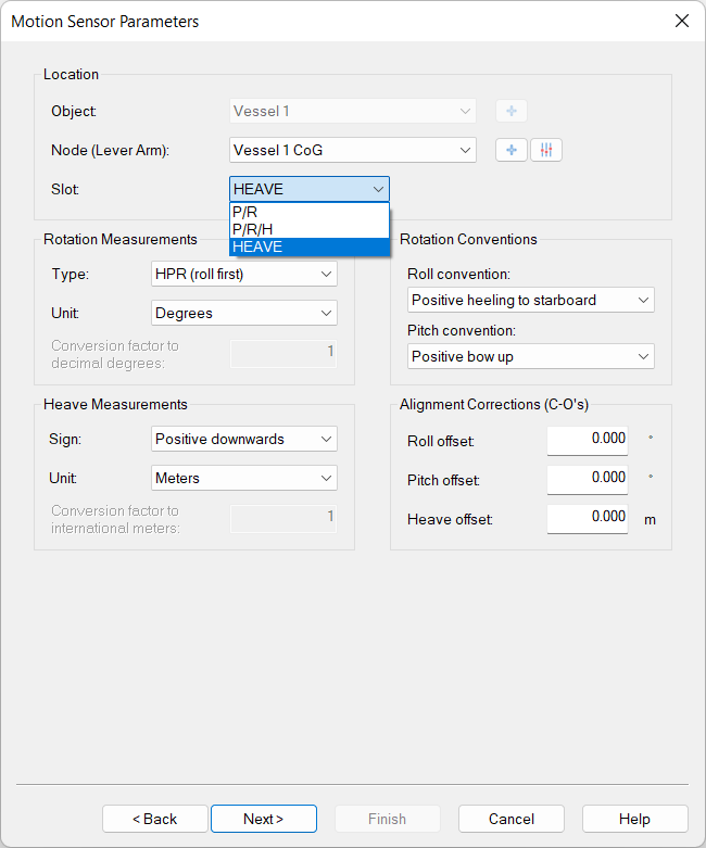
Setup of single Pitch Roll Heave sensor
-
Add a "Pitch Roll Heave sensor" system to your template and select the appropriate Ekinox driver
-
Select the port and/or IP address of the Ekinox unit
-
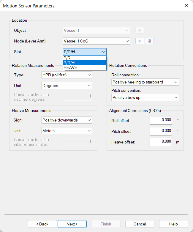
Rotation measurements
-
Unit: degrees
-
-
Rotation conventions
-
Roll convention: Positive heeling to starboard
-
Pitch convention: Positive bow up
-
-
Heave measurements
-
sign: Positive downwards
-
unit: Meters
-
-
Combining the data of both messages into a single Pitch Roll Heave sensor can be done by selecting slot value: R/P/H
Pitch and Roll from EKF_EULER message and Heave from SHIP_MOTION message.
Old Slot IDs are still compatible but when inside the configuration of the driver the Slot field needs to be updated.
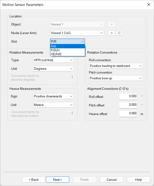
Setup of dual Pitch Roll Heave sensor
-
Add a "Pitch Roll Heave sensor" system to your template for pitch and roll. Select the appropriate Ekinox driver
-
Select the port and/or IP address of the Ekinox unit
-
Rotation measurements
-
Unit: degrees
-
-
Rotation conventions
-
Roll convention: Positive heeling to starboard
-
Pitch convention: Positive bow up
-
-
Select slot value: R/P
To only decode the Pitch and Roll from EKF_EULER message
-
Add a second "Pitch Roll Heave sensor" system to your template for the heave. Select the appropriate Ekinox driver
-
Select the port and/or IP address of the Ekinox unit
-
Rotation measurements
-
Unit: degrees
-
-
Rotation conventions
-
Roll convention: Positive heeling to starboard
-
Pitch convention: Positive bow up
-
-
Heave measurements
-
sign: Positive downwards
-
unit: Meters
-
-
Select slot value: HEAVE
To only decode the Pitch and Roll from SHIP_MOTION message
Old Slot IDs are still compatible but when inside the configuration of the driver the Slot field needs to be updated.
Warning
Make sure that both Pitch, Roll and Heave systems are included in the Computation.
Quality
The quality of the pitch and roll is decoded from the SBG_ECOM_SOL_ATTITUDE_VALID bit in the SOLUTION_STATUS field of the STATUS log.
The quality of the heave is decoded from the SBG_ECOM_HEAVE_VALID bit in the status field of the SHIP_MOTION log.
This leads to the following possible quality values:
|
Possible values |
Value meaning |
|---|---|
|
-1 |
Invalid data |
|
1 |
Valid data |
Acceleration, Velocity & Rotation Rate
Click to expand...
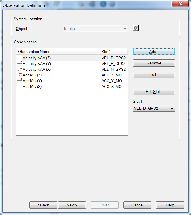
In order to decode acceleration, velocity and rotation from the Ekinox:
-
Add an "Acceleration, Velocity & Rotation Rate" system to your template and select the appropriate Ekinox driver
-
Select the port and/or IP address of the Ekinox unit
-
Slots
-
Velocity can be decoded from inertial data. GPS1 data, GPS2 data and Odometer data.
-
Acceleration can be decoded from IMU data and ship motion data.
-
Rotation can only be decoded from IMU data
-
The table below shows which slot value should be used to decode the data from the various log types:
-
|
Observation type |
Slot value |
Log |
|
|---|---|---|---|
|
Velocity |
VEL_N_NAV
|
EKF_NAV |
Velocity in North, east and and down direction from the INS system. |
|
VEL_N_GPS1
|
GPS_1_VEL |
Velocity in North, east and and down direction from GPS1. |
|
|
VEL_N_GPS2
|
GPS_2_VEL |
Velocity in North, east and and down direction from GPS2. |
|
|
Acceleration |
ACC_X_IMU
|
IMU_DATA |
Filtered accelerometer data. X, Y and Z axis, directly from the IMU. |
|
ACC_X_MOT
|
SHIP_MOTION |
Longitudinal, lateral and vertical acceleration at the location of the unit. |
|
|
Rotation rate |
There is no need to fill in a slot value for the rotation rate.
|
IMU_DATA |
Gyroscope X, Y and Z axis. Directly from IMU. |
Quality
The table below describes from which messages the quality numbers for the different observations are decoded and what the values mean:
|
Observation type |
Log |
Quality decoded from |
Possible values |
Meaning |
|---|---|---|---|---|
|
Velocity |
EKF_NAV |
SBG_ECOM_SOL_VELOCITY_VALID bit
|
1.0 |
Velocity value valid (velocity error < 1.5 m/s) |
|
-1.0 |
Velocity value invalid (velocity error >= 1.5 m/s) |
|||
|
GPS_1_VEL/
|
GPS_VEL_STATUS |
1.0 |
A valid solution has been computed |
|
|
-1.0 |
Not enough valid SV to compute a solution |
|||
|
-2.0 |
An internal error has occurred. |
|||
|
-3.0 |
Velocity limit exceeded. |
|||
|
Acceleration |
IMU_DATA |
SBG_ECOM_IMU_ACCEL_?_BIT
|
1.0 |
Accelerometer passed built in test |
|
-1.0 |
Accelerometer did not pass built in test |
|||
|
SHIP_MOTION |
|
0.0 |
Quality is unknown |
|
|
Rotation rate |
IMU_DATA |
SBG_ECOM_IMU_GYRO_?_BIT
|
1.0 |
Gyro passed built in test |
|
-1.0 |
Gyro did not pass built in test |
Miscellaneous System - Metadata
Miscellaneous System - Delayed heave
Qinsy Online
Position navigation system Quality
Click to expand...
The possible values of the quality indicator (displayed as "solution mode" in the Positioning System Display) depend on which log is used for the system.
If the position is decoded from the NAV log, the status is decoded from the POSITION_VALID bit in the STATUS log. If either GPS1 or GPS2 is used to decode the position, the quality is decoded from the GPS_POS_STATUS field in the LOG_GPSx_POS log in the following way:
-
If SBG_ECOM_GPS_POS_STATUS is equal to SBG_ECOM_POS_SOL_COMPUTED (a valid position has been computed), the variable SBG_ECOM_GPS_POS_TYPE is returned.
-
If SBG_ECOM_GPS_POS_STATUS is not equal to SBG_ECOM_POS_SOL_COMPUTED, SBG_ECOM_GPS_POS_STATUS multiplied by -1 is returned. This leads to the following possible values for the position quality:
|
Log |
Possible values |
Value meaning |
|---|---|---|
|
NAV |
0 |
No quality information available. |
|
GPS1/GPS2 |
-1 |
Not enough valid SVs to compute a solution. |
|
-2 |
An internal error has occurred. |
|
|
-3 |
The height limit has been exceeded. |
|
|
0 |
No valid solution available. |
|
|
1 |
An unknown solution type has been computed. |
|
|
2 |
Single point solution position. |
|
|
3 |
Standard Pseudorange Differential Solution. |
|
|
4 |
SBAS satellite used for differential corrections. |
|
|
5 |
Omnistar VBS Position (L1 sub-meter). |
|
|
6 |
Floating RTK ambiguity solution (20 cms RTK). |
|
|
7 |
Integer RTK ambiguity solution (2 cms RTK). |
|
|
8 |
Precise Point Positioning with float ambiguities. |
|
|
9 |
Precise Point Positioning with fixed ambiguities. |
|
|
10 |
Fixed location solution position. |
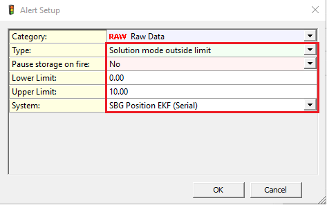
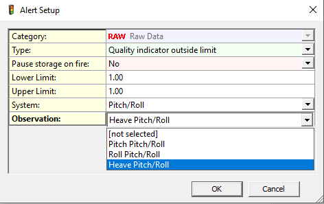
To display which Solution mode you are in an Alert display can be created to add the solution mode for the Positioning.
Change the Alert Setup to the Solution mode you are expecting and system you are using.
Gyro System Quality
Click to expand...
The possible values of the quality indicator (displayed as "solution mode" in the Positioning System Display) depend on which log is used for the system:
-
If the EULER log is used to decode heading, the quality of the data is decoded from the SBG_ECOM_SOL_HEADING_VALID bit in the SOLUTION_STATUS field of the LOG_STATUS log.
-
If either of the GPSx_HDT logs is used to decode the heading, the quality is decoded from the GPS_HDT_STATUS field in the log. This leads to the following possible values for the heading quality.
|
Log |
Possible values |
Value meaning |
|---|---|---|
|
EULER |
1 |
Heading data is reliable (Heading error < 1°) |
|
-1 |
Heading data is not reliable (Heading error >= 1°) |
|
|
GPS1/GPS2 |
1 |
A valid solution has been computed. |
|
-1 |
Not enough valid SV to compute a solution. |
|
|
-2 |
An internal error has occurred. |
|
|
-3 |
The height limit has been exceeded. |
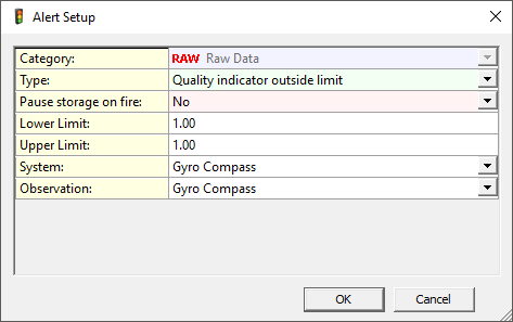
Select the Quality indicator outside limit.
If the value remains 1 a reliable heading is computed, if not see above what might be going on.
Pitch Roll Heave Quality
Click to expand...
The quality of the pitch and roll is decoded from the SBG_ECOM_SOL_ATTITUDE_VALID bit in the SOLUTION_STATUS field of the STATUS log.
The quality of the heave is decoded from the SBG_ECOM_HEAVE_VALID bit in the status field of the SHIP_MOTION_X log.
This leads to the following possible quality values:
|
Possible values |
Value meaning |
|---|---|
|
-1 |
Invalid data |
|
1 |
Valid data |
Select the Quality indicator outside limit.
If the value remains 1 a reliable motion is computed.
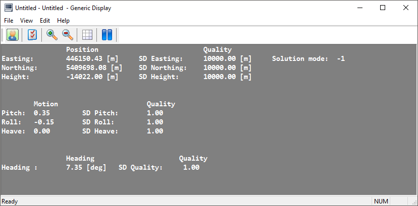
Generic Display
Click to expand...
Add a Generic Display and open this .xml :
-
SBG quality control.xml
(Only accessible when an internet connection is available)
To view the following information:
Additional Information
Click to expand...
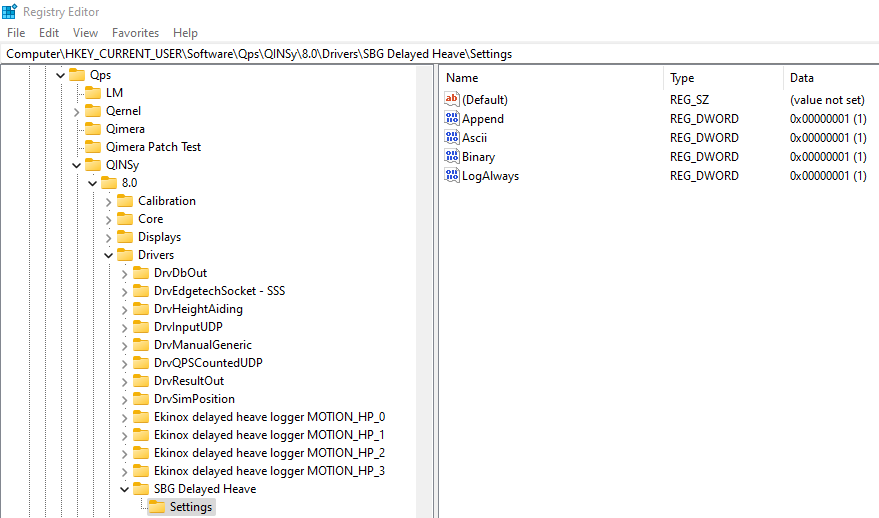
Registry Tweak settings
An advanced user may tweak the following registry key, in order to change the default behavior:
Qinsy 9.7 and newer
-
Computer\HKEY_CURRENT_USER\Software\Qps\QINSy\8.0\Drivers\SBG Delayed Heave\Settings
-
-
Append is by default set to 1. If you change it to 0, any existing file will be overwritten.
-
Ascii is by default set to 1. If you change it to 0, no ASCII file will be stored.
-
Binary is by default set to 1. If you change it to 0, no binary records will be stored.
-
LogAlways is by default set to 1. If you change it to 0, no data will be stored to disk.
-
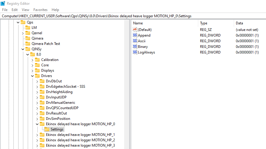
Qinsy 9.6.5 and older
-
Computer\HKEY_CURRENT_USER\Software\Qps\QINSy\8.0\Drivers\Ekinox delayed heave logger MOTION_HP_0\Settings
Computer\HKEY_CURRENT_USER\Software\Qps\QINSy\8.0\Drivers\Ekinox delayed heave logger MOTION_HP_1\Settings
Computer\HKEY_CURRENT_USER\Software\Qps\QINSy\8.0\Drivers\Ekinox delayed heave logger MOTION_HP_2\Settings
Computer\HKEY_CURRENT_USER\Software\Qps\QINSy\8.0\Drivers\Ekinox delayed heave logger MOTION_HP_3\Settings -
So it depends on which Slot value you used.
-
Append is by default set to 1. If you change it to 0, any existing file will be overwritten.
-
Ascii is by default set to 1. If you change it to 0, no ASCII file will be stored.
-
Binary is by default set to 1. If you change it to 0, no binary records will be stored.
-
LogAlways is by default set to 1. If you change it to 0, no data will be stored to disk.
-