
Description
Supported POS M/VS
-
This driver supports
POS M/V V4
POS M/V V5
POS L/V (except for Group 102, 103, 104, 105 and 112) (Only UDP output is supported.)
Driver to decode data from an Applanix POS MV™ or POS LV™ unit for the following system types:
-
-
Position
-
-
-
Heading
-
-
-
Motion
-
Pitch
-
Roll
-
Heave (Real Time)
-
-
Motion
-
Heave (True Heave - Import only, Replay required)
-
-
-
-
Time
-
Time Synchronization pulse (PPS)
-
-
-
True Heave (logging to separate file for import)
-
-
-
Speed
-
Bearing (True)
-
Driver Information
|
Driver |
Network - POS MV V5 |
Interface Type |
UDP |
Driver Class Type |
Counted |
|---|---|---|---|---|---|
|
Yes |
Input / Output |
Input |
Executable |
DrvQPSCountedUDP.exe POSMV PPS |
|
|
Related Systems |
|
||||
|
Related Pages |
|
||||
Coding Notes
Decoding Notes
-
-
Decoded data is always time stamped using Time1 from each group message. (See table below.)
-
The driver will automatically detect whether the POS MV™ time is GPS or UTC. For this it is important that the UTC to GPS correction in your template setup is correct (16 sec. as of 30 June 2012).
-
Qinsy needs to be interfaced to a valid Time Synchronization system
-
In case there are time critical sensors that are not sending time tagged data strings, the use of a QPS PPS and Fix Adapter is mandatory , otherwise time of arrival is used for time-stamping for those none time tagged data strings.
-
In case all time critical sensors are sending time tagged data, only a time message like ZDA (Group 112) or Group 7 can be used to to feed Qinsy's Time Synchronization System.
Important: select on forehand which time message you want to use from the system; ZDA (Group 112) OR Group 7. ENABLE ONLY THAT MESSAGE. DO NOT ENABLE BOTH MESSAGES AT THE SAME TIME.
-
-
-
Group 1
This is the standard navigation solution, and may or may not already be corrected for lever arms, but this is a setting outside Qinsy. And unlike group 102 or 103, it does not include Heave information.
-
POS MV™ - Recommended Setup
Depending on your application and what you wish monitor and record in Qinsy during your survey, there are several setups possible and shown below under: Example Setups.
Most often surveyors use Group 102, the Sensor 1 navigation solution which contains:
-
Latitude, Longitude, Altitude
-
will be decoded by a Position Navigation System,
-
-
Roll, Pitch and Heave
-
for a Pitch, Roll and Heave Sensor,
-
-
Heading
-
for a Gyro and Compasses System.
-
-
Quality indicators
-
will be decoded from associated Performance Metrics and Status Group messages. If you enable Group 102, then also enable Group 104 and 3 for the performance metrics and additional status information.
-
-
Always enable Group 10
Always enable Group 10, because the POS MV™ current Solution Mode will be determined from this group.
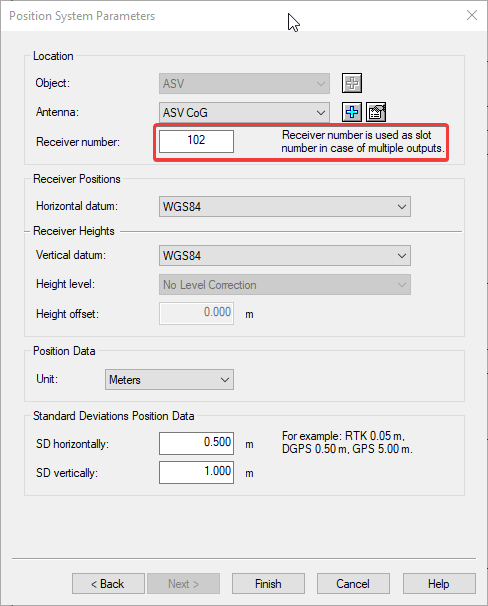
POS MV Reference Point
Please set up your POS MV system with the (most likely) C enter o f G ravity (CoG) as Ref erence point and set up Sensor 1 (group 102) to output in the CoG.
This will enable you to import the True Heave or SBET directly into the QPD files in the Survey Manager.
-
SBET
Applanix offers the option to Post Process the RAW observation recorded with PosView. This software package is called POSPac.
POSPac produces so called S moothed B est E stimated T rajectory (SBET) files which can be imported into the by Qinsy recorded databases through Replay/Raw Data Manager.
To be able to do this we strongly advise to add additional systems to your template database file to be able to import the SBET data without overwriting the original decoded data Online.
This will also enable you to compare the SBET results with the Online decoded results.
-
Example Setups
-
POS MV™ - Standard setup
A typical light-weight setup could be: Enable Group 3, 10, 20, 102 and 104 + 7 or 112
Define a template with:-
Positioning Systems (Receiver Number 102)
-
Gyro Compass systems (Slot numbers 102)
-
Pitch Roll and Heave Sensors (Slot number 102). Real Time Heave
-
Pitch Roll and Heave Sensors (Slot number 0). Dummy for True Heave import
-
Miscellaneous System - Status information - To monitor all kinds of status information in Generic Display (uses group 3, 10 and 20)
-
Miscellaneous System - True Heave® - Group 111
-
Time Synchronization System from Network Group 7 or Serial Group 112 - Do not enable both group messages at the same time on the POSMV.
-
-
POS MV™ - Extended Setup
A more heavy setup could be: Enable Group 1, 2, 3, 10, 11, 20, 102, 103, 104 and 105 + 7 or 112
Define a template with:-
3x Positioning Systems (Receiver Number 1, 102 and 103)
-
3x Gyro Compass systems (Slot numbers 1, 102 and 103)
-
3x Pitch Roll and Heave Sensors (Slot numbers 1, 102 and 103).
-
2x Miscellaneous System:
-
Status information - To monitor all kinds of status information in Generic Display (uses group 3, 10, 11 and 20)
-
-
Timing / Time Synchronization device from Group 7 or 112 - Do not enable both group messages at the same time on the POSMV.
If such a setup is used, make sure you really need all this data from the extra groups, because your database will grow in size tremendously.
True Heave and/or SBET results are to be applied to your data, proceed with Example 3 -
-
Import - True Heave and Smoothed Best Estimated Trajectory (DM-0297#SBET )
Select either one of the 2 above setups and add (before recording) another
-
Positioning Navigation System
-
Name: POS-MV Position-PP
-
Port number: 0
-
Receiver Number 0
-
-
Gyro Compass system
-
Name: POS-MV Heading-PP
-
Port number: 0
-
Slot number 0
-
-
Pitch Roll and Heave Sensor - (only Pitch and Roll)
-
Name: POS-MV Motion-PP
-
Port number: 0
-
Slot number 0
-
-
Pitch Roll and Heave Sensor - True Heave (only when using a POS MV™)
-
Name: POS-MV True Heave
-
Port number: 0
-
Slot number 0
-
-
-
POS LV™ (Trimble MX2 / Dynascan)
For the POS-LV you should enable Group 1,2, 3, 7 , 10,20
Define a template with:-
Positioning System (Receiver Number 1),
-
Gyro Compass system (Slot number 1)
-
Pitch Roll and Heave Sensor (Slot number 1)
-
Time Synchronization System (uses Group 7)
-
Add the systems as described above under 3 (SBET) for Post
-
-
See further below how to enable groups using the POSView Configuration software. (See below.)
-
Interfacing Notes
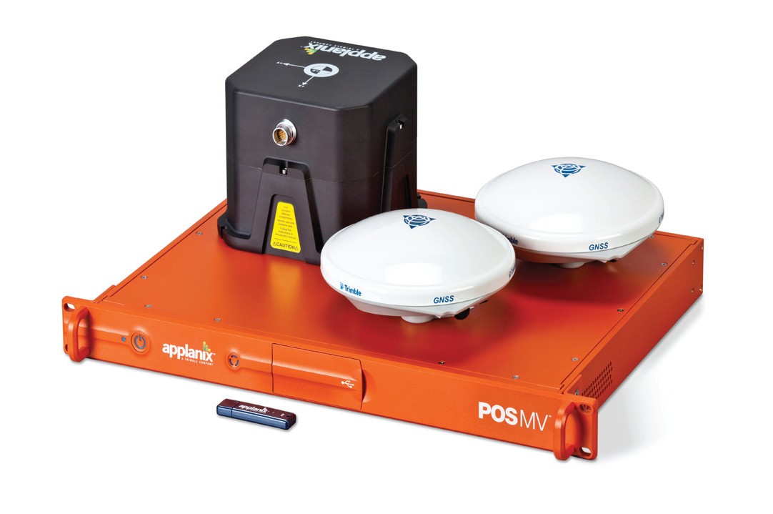
All communication to and from the POS MV™ unit goes via the on-board LAN network.
The exact LAN IP address of the unit should be provided by the manufacturer. Normally Applanix configures their units with IP address 129.100.1.2xx.
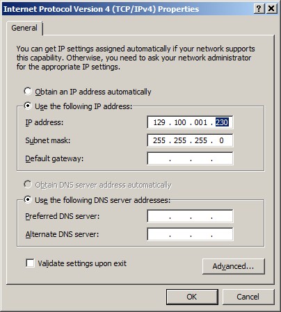
The LAN IP address of your computer's network should be in the same range, except for the last digit. This must be a unique number!
Use for the subnet mask the values 255.255.255.0
-
Windows XP:
Control Panel, Network Connections, Click right-mouse on Local Area Connection, Properties, Internet Protocol (TCP/IP), Properties... -
Windows Vista:
Control Panel, Network and Sharing Center, Tasks, Manage network connections, Click right-mouse on Local Area Connection, Properties, Internet Protocol Version 4 (TCP/IPv4), Properties... -
Windows 7:
Control Panel, Network and Sharing Center, Change adapter settings, Click right-mouse on Local Area Connection, Properties, Internet Protocol Version 4 (TCP/IPv4), Properties...
The POS MV™ unit only broadcasts group messages via a fixed UDP network port 5602, and not via serial output.
Enabling other groups than the ones described in this document is allowed but not recommended because it causes extra network traffic and data from these messages is not used by the driver.
When working with multiple POS units Qinsy can filter the UPD messages on Source IP. See Database setup for more information
System Configuration
Basic How-to
The POS MV™ unit must be configured to output so-called binary group messages. Each group will be identified by a Group ID and can be enabled using Applanix' own configuration software (MV-POSView).
The following main group messages are supported by this driver:
Further, the following groups can also be decoded. They contain additional information about the data from the groups above:
|
Time Synchronization (PPS) Time |
Special group for decoding true heave data, which may be used for post-processing:
|
Real-time Heave and True Heave |
Special group for decoding encapsulated NMEA strings, and in particular the NMEA ZDA sentence which can be used for Time Synchronization time tagging:
|
NMEA Strings (POS MV™ only) - Note that only NMEA ZDA will be recognized, other NMEA sentences are ignored |
All groups are explained in the tables further down the page.
To enable/disable the required groups that should be broadcast by the POS MV™ unit, you need to use the POS MV Configuration software that comes with the unit. At the time of this writing, MV-POSView v3.4.0.0 from Applanix can be used.
This paragraph does not replace the MV-POSView software manual, but only emphasizes how to enable or disable the required group messages.
This software needs a network connection with the POS MV™ unit in order to communicate with it.
The unit has by default IP address 129.100.1.231, so in that case you should configure the network card of your computer that is running the software to IP address 129.100.1.230, Subnet mask 255.255.0.0.
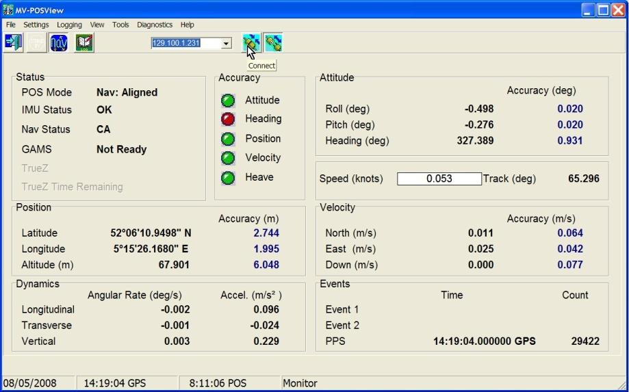
Note that if you do not connect, and you stay in so-called 'monitor' mode, then you can not modify and save settings.
To enable/disable the required groups, use the toolbar [Connect] button to connect, then select Ethernet Realtime from the pull down menu Logging:
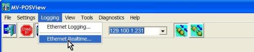
The following dialog will be opened:
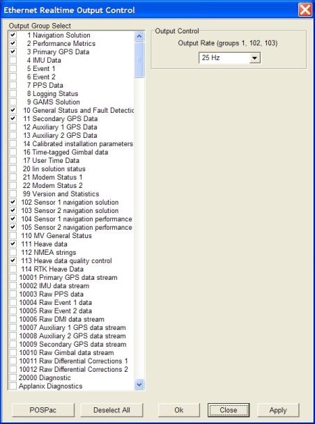
It is recommended to only enable groups that are required or desired. Do not enable groups that are not used by this driver. Due to the enormous amount of data transmitted, it may cause unnecessary overload on the driver's performance.
The recommended output rate for Group 1, 102 and/or 103 is 25 Hz. Only when really necessary, may the output rate be increased, but the recommended maximum is 50Hz!
Notice fixed output rates for:
-
Group 111 is always 25Hz,
-
Additional Groups (2, 3, 10, 11, 20, 104, 105) is 1Hz.
Time Synchronization
-
NMEA ZDA
In case you want to use the NMEA ZDA sentence for Time Synchronization time-tagging inside Qinsy, select pull down menu Settings, Input/Output Ports..., set the Output Select to NMEA, and enable the $--ZDA message at 1Hz update rate.
The talker id may be 'IN' or 'GP'.
Further, select from pull down menu Logging, Ethernet Realtime... and make sure to enable Group 112 (NMEA strings)
IMPORTANT: Group 7 should then be disabled. -
Binary Group 7
When using binary group 7 for time synchronization in Qinsy, please make sure that the ZDA output is disabled on the POSMV or Group 112 entirely.
Save Settings
After making modifications successfully, save the settings to the unit using the 'Save Settings' option from the Settings pull-down menu, otherwise they will be lost after switching off the unit.
Connection issues
Data transmitted by the POS MV™ unit goes via UDP port 5602.
The MV-POSView will listen to this port, as Qinsy does. It is possible to have both Qinsy as well as the MV-POSView software open at the same time.
However, if you notice problems that in one of the two programs data is not received via UDP port 5602, you should first start Qinsy, and then MV-POSView.
Database Setup
Basic How-to
As the Qinsy database setup for a POS-MV system can be quite complex, an example template can be downloaded at the Additional info section.
Setups using multiple POS-MV units are possible in Qinsy v8.18 and higher.
This functionality is enabled by checking the 'Filter on data source' flag in the system setup:
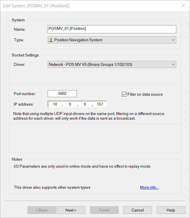
In the IP address field, fill in the IP address of the POS-MV unit this system should decode.
PLEASE NOTE: When using multiple POS-MV systems, make sure that the POS-MV units are configured to output the data as a UDP broadcast and not as uni-cast.
Make sure that the subnet mask is set to 255.255.255.0 on both POSMV systems and the Qinsy PC's
When using a single POS-MV system, the 'Filter on data source' can be left unchecked.
Position Navigation System
Online this driver can decode binary group:
-
Vessel / Car (POS LV)
-
Output location Sensor 1 (POS MV standard setup)
-
Output location Sensor 2
-
Raw antenna position
-
10001 (Main antenna location)
-
10009 (Secondary antenna location)
Depending on the firmware if this is supported or not.
-
In order to decode a position from the POS MV™:
-
Add a Position Navigation System to your template and select the driver "Network - POS MV V5 (Binary Groups 1/102/103/1000n)".
-
The port number must be the same as the UDP port number on the POS MV™ unit. By default this will be 5602.
Important:
The Receiver number on the next page of the system wizard must be the Group ID number that you want to decode.
Enter 1 if you wish to decode latitude, longitude and altitude from the standard navigation solution, which is part Group 1.(POS LV)
Enter 102 if you wish to decode latitude, longitude and altitude for output location Sensor 1, which is part Group 102. (POS MV standard setup)
Enter 103 if you wish to decode latitude, longitude and altitude for output location Sensor 2, which is part Group 103.
-
Select for Horizontal and Vertical datum WGS84.
-
SBET
When you want to import DM-0297#SBET files it is advised to add another Position Navigation System-
Name: POS-MV Position-PP
-
Port number: 0
-
Receiver Number 0
-
Gyro Compass System
This driver can Online decode binary group:
-
Vessel
-
Output location Sensor 1 (standard setup)
-
Output location Sensor 2
In order to decode a heading from the POS MV™:
-
Add a Gyro and Compass System to your template and select the driver "Network - POS MV V5 (Binary Groups 1/102/103)".
-
The port number must be the same as the UDP port number on the POS MV™ unit. By default this will be 5602.
Important:
The Slot number on the next page of the system wizard must be the Group ID number that you want to decode.
Enter 1 if you wish to decode the heading from the standard navigation solution, which is part of Group 1. (POS LV)
Enter 102 if you wish to decode the heading of output location Sensor 1, which is part of Group 102. (POS MV standard setup)
Enter 103 if you wish to decode the heading of output location Sensor 2, which is part of Group 103. -
SBET
When you want to import DM-0297#SBET files it is advised to add another Gyro Compass System-
Name: POS-MV Heading-PP
-
Port number: 0
-
Slot number 0
-
Pitch Roll Heave Sensor
This driver can Online decode binary group:
In order to decode the attitude from the POS MV™:
-
Add a Pitch, Roll and Heave Sensor System to your template and select the driver "Network - POS MV V5 (Binary Groups 1/102/103)".
Group 1
Note that the standard navigation solution, Group 1, has no heave observation.
-
The port number must be the same as the UDP port number on the POS MV™ unit. By default this will be 5602.
Important:
The Slot number on the next page of the system wizard must be the Group ID number that you want to decode.
Enter 1 if you wish to decode the roll and pitch from the standard navigation solution, which is part of Group 1. (POS LV)
Enter 102 if you wish to decode the roll, pitch and heave of output location Sensor 1, which is part of Group 102. (POS MV standard setup)
Enter 103 if you wish to decode the roll, pitch and heave of output location Sensor 2, which is part of Group 103.
Rotation Convention and Sign:
|
Observation |
Positive when |
|---|---|
|
Roll |
heeling to starboard |
|
Pitch |
bow up |
|
Heave |
downward |
For all a-priori SD values, please consult the POS MV™ Accuracy Specifications.
-
True Heave
When you are using a POS MV™ unit and wish to import the binary True Heave file (valid for output location Sensor 1 only) into the recorded database (*.db) files after surveying, it's advised to do the following steps before recording your survey:-
Add an additional Pitch Roll and Heave Sensor to your template DB.
-
Name it POS-MV - True Heave
-
Port number: 0
-
Node: Output location Sensor 1
-
Slot number: 0
-
Add a Miscellaneous System - True Heave® - Group 111 to your template database (see below) to enable the recording of the required files
-
-
SBET
When you want to import DM-0297#SBET files it is advised to add another Gyro Compass System-
Name: POS-MV Motion-PP
-
Port number: 0
-
Slot number 0
-
Heave
When importing the POSPac SBET file the motion data will not contain Heave values!!!
Instead of the Heave you could use the True Heave and import it into a separate system. To Import the True Heave into a recorded DB file it is advised to add another system called: POS-MV True Heave (see below)
Miscellaneous System - True Heave® - Group 111
This driver can Online decode binary Group 111
Only the POS MV™ unit is capable of broadcasting Group 111 messages, containing Real-time Heave and True Heave data for output location Sensor 1.
True Heave is better than the Real-time Heave for output location Sensor 1 (Group 102), but only available with a delay of about 100 to 200 seconds.
Therefore the online acquisition system can not use the True Heave in real-time, but it is possible to log this data to an external file on disk and import the data during processing:
-
Setup
-
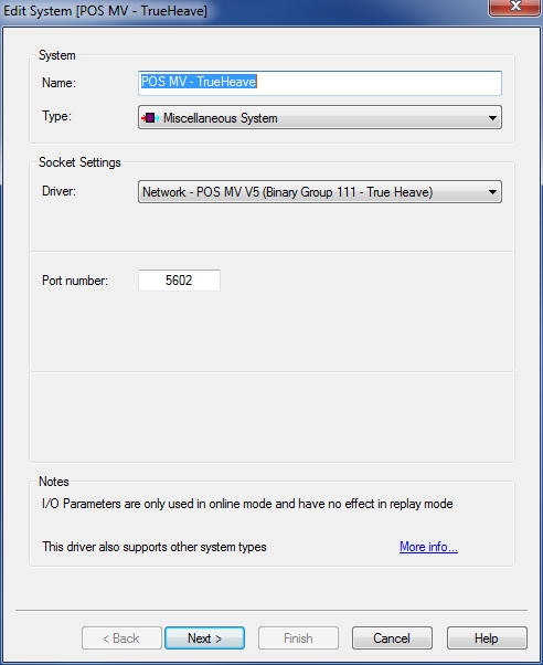
Add a Miscellaneous system to your template and select driver "Network - POS MV V5 (Binary Group 111 - True Heave)".
-
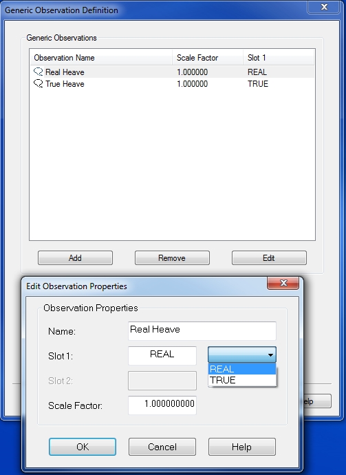
The port number must be the same as the UDP port number on the POS MV™ unit. Normally this will be 5602. There is no need to add an observation on the next wizard page, although you may add two generic observations:
-
Name the first one "True Heave", and set the Slot Id to "TRUE".
-
Name the second one "Real Heave", and set the Slot Id to "REAL".
-
By adding these two generic observations, you may monitor on-line the values of these two. Mind that heave convention for Group 111 is fixed to positive downward, from the sensor location, in the gravity direction.
-
-
-
Online
As soon as you go on-line and your template contains this Miscellaneous system 2 file types are logged:-
Binary file
A binary file will be created in your project's Import folder, containing all incoming Group 111 messages.
The binary file contains the following information:-
True Heave, True Heave RMS, Real Heave, Real Heave RMS, and Heave Time 1
File name convention will be "POSMV TRUE HEAVE - <System Name> (dd-mm-yyyy).bin".
-
-
ASCII file
At the same time an ASCII file is created in the same folder with the same file name, but with extension *.txt.
This file contains a readable representation of Group 111 data:
Comma-separated fields showing:-
UTC date and time,
-
Difference between Real and True heave,
-
True heave,
-
True heave RMS,
-
Real heave and
-
Real heave RMS.
Example:
DD-MM-YY, UTC, (REAL-TRUE), TRUE HEAVE, RMS, REAL HEAVE, RMS
02-08-06,14:31:56.196,0.0025,-0.0009,0.0010,-0.0035,0.0215
02-08-06,14:31:56.546,0.0025,-0.0010,0.0010,-0.0035,0.0215
02-08-06,14:31:56.797,0.0026,-0.0010,0.0010,-0.0035,0.0215
02-08-06,14:31:57.137,0.0026,-0.0010,0.0010,-0.0035,0.0215
-
-
True Heave logging
If True Heave data is to be used, it is important to remain Online for at least 3 -5 minutes after logging has stopped in order for the stored file to cover all of the logged data.
-
Offline / Replay
-
Binary file
The True Heave recorded in the binary file can be imported into the recorded DB files and need to be replayed after the data is imported.
Note that the True Heave only imports the heave value and no Heading, Pitch and Roll.
When replaying the data make sure to set the following priorities for the True Heave observations in the computation setup :-
Heading
-
Heading Real Heave - Primary
-
Heading True Heave - Secondary or lower
-
-
Pitch and Roll
-
Motion Real Heave - Primary
-
Motion True Heave - Secondary or lower
-
-
Heave
-
True Heave - Primary
-
Real Heave - Secondary
-
The above settings could also be used when recording data online, as the Heave will automatically fall through to the secondary device because the True Heave is not decoded online by the Pitch Roll and Heave Sensor : POS-MV - True Heave.
-
-
ASCII file
-
Apply True Heave to QPD files
This text file may be used in the Validator, when selecting the Shift [Z] by File Filter, because the third column contains the difference between the Real and True Heave.
The difference (True - Real) is applied to the CoG and footprint data.
You need to make sure that the POS MV™ unit was set up to output the True Heave in the Center of Gravity (CoG) of Qinsy.
-
Registry Tweak settings
-
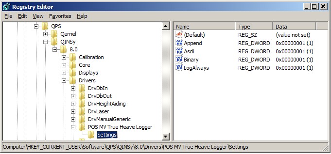
An advanced user may tweak the following registry key, in order to change the default behavior:
"HKEY_CURRENT_USER\Software\QPS\Qinsy\8.0\Drivers\POS MV True Heave Logger\Settings"
-
-
Append is default set to 1. If you change it to 0, any existing file will be overwritten.
-
Ascii is default set to 1. If you change it to 0, no ASCII file will be stored.
-
Binary is default set to 1. If you change it to 0, no binary Group 111 records will be stored.
-
LogAlways is default set to 1. If you change it to 0, no data will be stored to disk.
-
-
-
Processing
Please refer to driver manual POS MV V5 (Binary Group 111 - True Heave for more information about importing this ASCII or binary file into your QPD files.
Miscellaneous System - Status Information
This driver can decode binary groups Online: 3 + 10 + 11 + 20 + 10001 + 10009
-
In order to monitor all kinds of status information from the POS MV™:
-
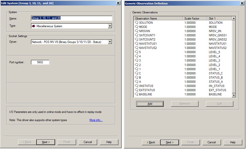
Add a Miscellaneous System to your template and select the driver "Network - POS MV V5 (Binary Groups 3/10/11/20/1000n - Status)".
-
The port number must be the same as the UDP port number on the POS MV™ unit. By default this will be 5602.
-
On the next page you may add up to 21 generic observation, each one with its own unique case-sensitive Slot Id:
To decode the GPS receiver type from Group 10001 use Slot Id ‘GNSS1_TYPE’ and the GPS receiver type from Group 10009 use Slot Id ‘GNSS2_TYPE’.
The value of the decoded receiver type can be looked up in the POS MV User’s Manual Table 12.
-
|
Group |
Slot Id |
Description |
|---|---|---|
|
3 |
NAVSTATUS1 |
Sensor 1 GNSS Navigation solution status. See table 9 |
|
NRSV_GNSS1 |
Number of SVs tracked from Sensor 1 GNSS |
|
|
7 |
PPS_COUNT |
Incrementing PPS Counter: the number of PPS messages since power-up and initialization of the GPS receivers |
|
TIME_SYNC |
Time synchronization status (0=Not synchronized, 1=Synchronizing, 2=Fully synchronized, 3=Using old offset) |
|
|
11 |
NAVSTATUS2 |
Sensor 2 GNSS Navigation solution status. See table 9 |
|
NRSV_GNSS2 |
Number of SVs tracked from Sensor 2 GNSS |
|
|
10 |
STATUS_A |
Decimal value representation of General Status A |
|
STATUS_B |
Decimal value representation of General Status B |
|
|
STATUS_C |
Decimal value representation of General Status C |
|
|
LEVEL_1 |
Decimal value representation of FDIR Level 1 |
|
|
LEVEL_2 |
Decimal value representation of FDIR Level 2 |
|
|
LEVEL_3 |
Decimal value representation of FDIR Level 3 |
|
|
LEVEL_4 |
Decimal value representation of FDIR Level 4 |
|
|
LEVEL_5 |
Decimal value representation of FDIR Level 5 |
|
|
EXT_STATUS |
Decimal value representation of Extended Status |
|
|
EXTSTATUS2 |
Decimal value representation of Extended Status 2 |
|
|
SOLUTION |
Derived from a combination of all Group 10 status flags.
1 means Loosely coupled solution, 2 means Auxiliary GPS in use, 3 means DR mode and -1 means undefined. |
|
|
MODE |
Derived from a combination of all Group 10 status flags.
|
|
|
20 |
NRSV_IIN |
Number of satellites in the IIN solution |
|
BASELINE |
The baseline length is the computed distance between primary GNSS antenna and Base reference GNSS antenna |
|
|
IIN_STATUS |
The IIN processing status.
|
-
Timing
Decoded data is always time stamped using Time1 from each group message. (See table below.)
The driver will automatically detect whether the POS MV™ time is GPS or UTC. For this it is important that the UTC to GPS correction in your template setup is correct (18 sec. as of January 2017).
Qinsy needs to be interfaced to a valid Time Synchronization system, otherwise time of arrival is used for time-stamping.-
Group 7 - Time Synchronization Time.
Time Synchronization Time from the POS MV™ or POS LV™ unit can be used for Time Synchronization time-tagging inside Qinsy:
-
Enable Group 7 using the POS MV software
-
NOTE: Group 7 vs Group 112
Do not enable Group 112 in combination with an NMEA ZDA sentence. This group should be disabled, or the ZDA message should not be part of the selected NMEA sentences.
-
-
Add a Time Synchronization system to your template and select driver "Network - POS MV V5 (Binary Group 7 - PPS Time)".
-
The port number must be the same as the UDP port number on the POS MV™ unit. By default this will be 5602.
-
On the next page enable the use of your Time Synchronization adapter, or leave it disabled if you do not have a Time Synchronization pulse interfaced to Qinsy.
Normally the use of a Time Synchronization adapter is highly recommended, but note that in a setup where all other systems are already UTC time-tagged from an external time source (GNSS receiver), there is no need for Qinsy to use a Time Synchronization adapter.
-
-
Group 112 - NMEA strings .
Time Synchronization Time from the NMEA ZDA sentence can be used for Time Synchronization time-tagging inside Qinsy.
The POS MV™ unit is capable of outputting several NMEA sentences (ASCII), but only via serial communication and not via network UDP. However the POS MV™ has the option the enable Group 112.
When Group 112 is enabled, all the selected NMEA sentences will be broadcasted via UDP, encapsulated inside this binary group message.-
This driver will only recognize one NMEA format: $GPZDA (or $INZDA), which can be used for Time Synchronization time-tagging inside Qinsy.
-
All other NMEA formats are ignored.
-
First enable the ZDA message at 1 Hz using the POS MV software and enable Group 112.
-
NOTE: Group 7 vs Group 112
Do not enable Group 7 in combination with an NMEA ZDA sentence. This group should be disabled.
-
-
Add a Time Synchronization system to your template and select driver "Network - POS MV V5 (Binary Group 112 - NMEA ZDA)".
-
The port number must be the same as the UDP port number on the POS MV™ unit. Normally this will be 5602.
-
On the next page enable the use of your Time Synchronization adapter, or leave it disabled if you do not have a Time Synchronization pulse interfaced to Qinsy.
Normally the use of a Time Synchronization adapter is highly recommended, but note that in a setup where all other systems are already UTC time-tagged from an external time source (GNSS receiver), there is no need for Qinsy to use a Time Synchronization adapter.
-
-
Not using a PPS Pulse
Normally the use of a Time Synchronization adapter is highly recommended, but note that in a setup where all other systems are already UTC time-tagged from an external time source (GNSS receiver), there is no need for Qinsy to use a Time Synchronization adapter.
-
Speed Log
This driver can decode the NMEA VTG string encapsulated in binary group 10001 and/or 10009The course over ground can be decoded as Bearing (True) observation and the speed over ground can be decoded as Speed observation:
-
Add a Speed Log system type to your template and select the driver "Network (UDP) - POS MV V5 (Binary Group 1000n - NMEA VTG)".
-
The port number must be the same as the UDP port number on the POS MV™ unit. By default this will be 5602.
-
On the next page you can add two observation types: a Bearing (True) and a Speed observation.
Note that the other observation types are not supported so there is no need to add one of these.
Make sure to select Slot 1 id ‘10001’ for the primary GNSS receiver data and ‘10009’ for the secondary GNSS receiver data.
When you go to the last wizard page you can ignore the warning that the same Slot 1 id is used so just continue on.
-
Qinsy Online
The solution mode is an important figure to monitor.
Each defined Position Navigation System from your template setup has one and can be monitored using one of the following displays:
-
Alert Display
-
Raw Alert, Solution mode outside limit
-
-
Generic Display
-
RAW Data, Positioning, item Solution Mode, or RESULT DATA, Nodes, item Solution Mode
-
-
Node QC Display
-
Enable column Solution Mode
-
-
Positioning System Display
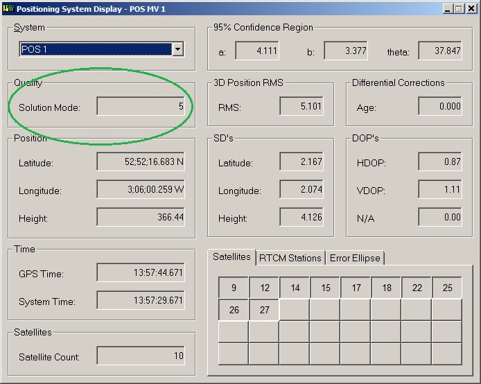
The solution mode value depends on the current solution of the GPS/GNSS receiver.
There are four possible solutions:
-
Tightly coupled
-
Loosely coupled
-
Auxiliary GPS in Use
-
Dead Reckoning (DR)
The solution mode can have the following values:
|
Solution |
Mode |
|---|---|
|
Tightly coupled solution (0) |
|
|
IIN in narrow lane RTK aided mode |
0 |
|
IIN in wide lane RTK aided mode |
1 |
|
IIN in float RTK aided mode |
2 |
|
IIN in code DGPS aided mode |
3 |
|
IIN in RTCM DGPS aided mode |
4 |
|
IIN in C/A GPS aided mode |
5 |
|
IIN GPS aiding is loosely coupled |
6 |
|
DR mode (3) |
|
|
No solution - IIN in DR mode |
7 |
|
Loosely coupled solution (1) |
|
|
Sensor 1 GPS in P-code mode |
10 |
|
Sensor 1 GPS in narrow lane RTK mode |
11 |
|
Sensor 1 GPS in wide lane RTK mode |
12 |
|
Sensor 1 GPS in float RTK mode |
13 |
|
Sensor 1 GPS in Differential mode |
14 |
|
Sensor 1 GPS in C/A mode |
15 |
|
Sensor 1 GPS in Marinestar HP mode |
20 |
|
Sensor 1 GPS in Marinestar XP mode |
21 |
|
Sensor 1 GPS in Marinestar VBS mode |
22 |
|
Sensor 1 GPS in PPP mode |
23 |
|
Sensor 1 GPS in Marinestar G2 mode |
30 |
|
Sensor 1 GNSS in Trimble RTX mode |
31 |
|
Sensor 1 GPS in Marinestar HPXP mode |
32 |
|
Sensor 1 GPS in Marinestar HPG2 mode |
33 |
|
Sensor 1 GNSS in Marinestar G4 mode |
34 |
|
Sensor 1 GNSS in Marinestar G2+ mode |
35 |
|
Sensor 1 GNSS in Marinestar G4+ mode |
36 |
|
Auxiliary GPS in use (2) |
|
|
Auxiliary GPS in P-code mode |
110 |
|
Auxiliary GPS in narrow lane RTK mode |
111 |
|
Auxiliary GPS in wide lane RTK mode |
112 |
|
Auxiliary GPS in float RTK mode |
113 |
|
Auxiliary GPS in Differential mode |
114 |
|
Auxiliary GPS in C/A mode |
115 |
|
Auxiliary GPS data gap |
117 |
|
Auxiliary GPS in Marinestar HP mode |
120 |
|
Auxiliary GPS in Marinestar XP mode |
121 |
|
Auxiliary GPS in Marinestar VBS mode |
122 |
|
Auxiliary GPS in PPP mode |
123 |
|
Undefined |
-1 |
-
Computation Setup
Besides monitoring you can also use this value as a threshold for your computation priority.
Select the used Position Navigation System in the Controller's Computation Setup page, and enable the Solution Mode Threshold.
For example, set the minimum and maximum threshold to 0 and 2 in case you only want to accept an IIN solution with fixed and/or float RTK: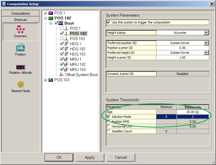
Additional Information
Applanix publications:
PUBS-ICD-000027: POS TNG3 Core User ICD
PUBS-ICD-000033: POS MV Model 320 V3
PUBS-ICD-000035: POSMV V4 User ICD
PUBS-ICD-000551: POS MV V4 User ICD
PUBS-ICD-004089: POS MV V5 User ICD
Drivers IO Notes
Command line parameter description for "drivers.io" file. Please do not edit this drivers.io file, or only after contacting the QPS Support department.
Parameter 'POSMV' tells the driver to expect data from a POS MV™ unit.
Parameter 'Time Synchronization' (previously PPS) tells the driver to use the time fields of the data string to time stamp the data. It is highly recommended to use these time fields of the data.
If this cmdline parameter is omitted, or your template has no setup for a Time Synchronization interface driver, then time stamping of the data is done at time of receiving.
Example Template Database
The following Example POSMV template database can be used to assist in a template for POS MV systems.
Please keep in mind that the following items need to be set:
-
Geodetic settings;
-
Node Offsets / Lever arms;
-
Port numbers are standard/default 5602;
It is advised to read the Drivers Manual completely to assure no errors are made.
Additional Logfile
The driver may log debug and other general information to a log file in the current Project's LogFiles folder.
Creating such logfiles is mainly for debug purposes; whenever you encounter problems and/or request help from QPS please submit these files to the support team.
In order to do so you must change the following advanced registry key while being offline:
HKEY_CURRENT_USER\Software\Qps\QINSy\8.0\Drivers\<DRIVER'S EXE NAME>\Settings\LogFile Level
Where the <DRIVER’S EXE NAME> depends on the driver you are using: serial (DrvQPSCounted), network UDP (DrvQPSCountedUDP) or network TCP (DrvQPSCountedTCP).
-
When the LogFile Level value is 0 then no log files will be created - DEFAULT.
-
When the LogFile Level value is 1 then a log file will be created with very little information: time of going online and time of going offline.
-
When the LogFile Level value is higher than 1 (e.g. 2, 3 or 4) then it will reveal all detected group messages from the decoded data stream - RECOMMENDED.
-
When the LogFile Level value is 'F' Hex (15 decimal) or higher then it will show all decoded NMEA string from possible group 10001 records plus additional group header information.
Filename convention of the logfile will be: "<Driver>.<System Name>.<Date> - <Counter>.log", where the counter field will increment automatically to make each log file unique.
The default registry key value is 0: no log files are created. You may change the key to the recommended value of 2.
Change the key to 'F' hex (15dec) in case you encounter problems so QPS support can help you investigating.