
Planning
The following provides a brief overview of Line Planning.
Additional Mainlines
|
Planning |
|
|---|---|

|
Select files and lines to use during a survey. |

|
Plan selected lines and see the statistics of the survey. |

|
Additional settings for line planning. |
|
|
Add mainlines for other objects to use such as ROVs, pipe laying barges or for use on curved rivers. |

|
Select and define terrain models to use as a reference layer in a Profile Display. |

Much more detailed descriptions are available here:
-
In the Controller's Help pages
-
In the Knowledge Base under Session Setup - Planning
The Planning function is used to import line database files (*.QGF) and to organize the use of points (waypoints), lines and polylines (routes).
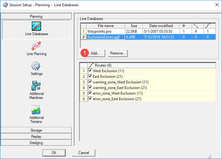
Line Databases
Use this button to add any line database files needed either to run dredging operations and/or for visualization purposes, e.g. dredging exclusion zones.

Browse to the correct folder and select the appropriate *.QGF file in the standard Windows dialog that appears. Add additional files if necessary.
All the waypoints, lines and routes that are defined in the *.QGF file are displayed and they can be turned on/off individually.
Line Planning


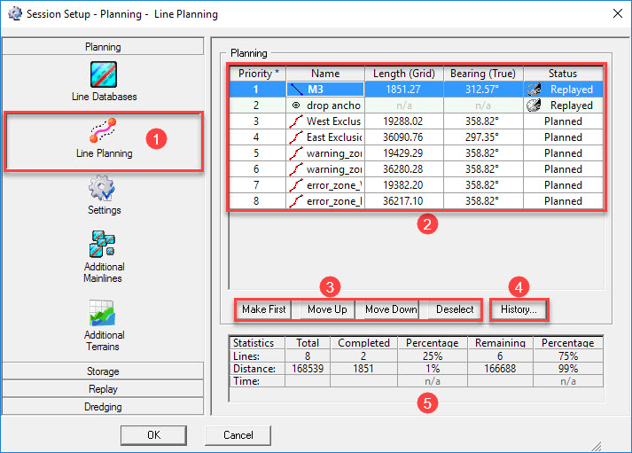


Depending upon settings under Storage - Control, this line order is used during operations.

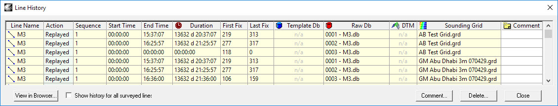
The history is stored in an XML file "Session.History.<Project Name>.xml" which is stored in the Project folder \Export\QMS.

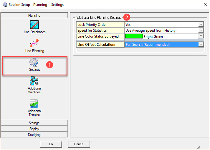
Settings


|
Additional Line Planning Settings |
|
|---|---|
|
Lock Priority Order |
Lock Order can be used to keep the order of the selected lines in case another line is set as mainline. |
|
Speed for Statistics |
To calculate an estimated time for the duration of the survey a speed value is needed:
|
|
Line Color Status Surveyed |
This color will be used in the Navigation Display in case the color option for the "Lines from planning" is set to "Use History Color".
|
|
Line Offset Calculation |
Method of Line Offset Calculation for the Steered Node when the mainline is a Route:
Notice that when the Narrow Search method is selected, a one-time full search is done in the following events:
|
|
Maximum Distance Across |
Entering the maximum allowed distance across before the narrow search algorithm will search all sections again in order to determine the current section. |
Additional Mainlines
It is possible to add mainlines to use for other objects to follow. For example with an ROV one might not be interested in its offset from the mainline that is used by the survey vessel, but rather in the offset from a desired line.
Or, when sailing along a river axis, the route along the tidal stations should be selected: 'Just' calculating the closest horizontal distance for tide interpolation is not enough, because a river can be curved.
In all displays where lines can be selected, additional mainlines can be selected too: Navigation Display, Alpha Numerical Display, Generic Display and Profile Display.
When a different additional mainline is needed, the line must be selected here in the Additional Mainlines menu. This will change the additional mainline in all the used displays at the same time.
When a new additional mainline is needed you can create the route using the Waypoint Planning option in the Navigation Display.
For example a quick way to create a new additional mainline along a river (for tide interpolation purposes) just click along the tide stations which will be passed.


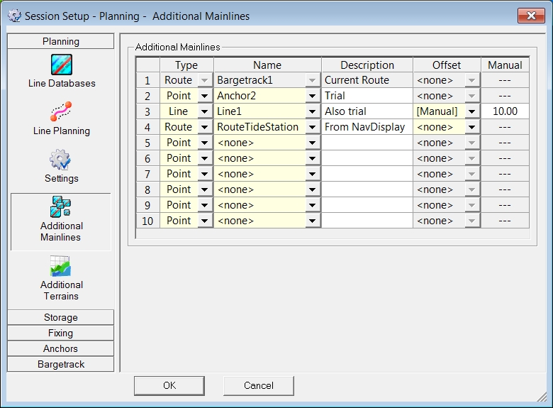

|
Additional Mainlines |
|
|---|---|
|
Type |
Choose between Point, Line or Route. |
|
Name |
Only names of the type as selected in the first column will be shown. |
|
Description |
This description is for the user only and will not appear in the display. |
|
Offset |
If needed, select Manual or (in specific cases) a special observation.
|
|
Manual |
Enter a value for the lines where a Manual Offset was selected.
|
Additional Terrains
An Additional Terrain is defined by a layer from either a grid, a QINSy Mapping *.pro file or a manual level which can then be selected as the terrain in one or more Profile Displays.
When multiple displays are used, for example with fore, side and aft views then the terrain only needs to be selected once, here in the Session Setup.
For more information see the Profile Display's Select - Terrain menu.


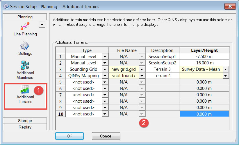

|
Additional Terrains |
|
|---|---|
|
Type |
Three terrain types can be selected:
|
|
File Name |
Select the file name of the Sounding Grid file or QINSy Mapping file. |
|
Description |
The description shown here, will be used in the Profile Display to select the Terrain. Enter a different name if necessary. |
|
Layer / Height |
If a Sounding Grid or QINSy Mapping file is selected, select the Layer that should be used.
|
Return to: top of page
Return to: TSHD Session Settings