
On this page:
Configuring Raw Datagram Output
The required datagrams must first be enabled for output in the manufacturer's system control software. The following tables list the datagrams needed.
R2 Sonic 202x-Series
|
|||||
|
R2 Sonic 2024, 2022, 2020 |
|||||
|
Application |
Bathymetry
(BTH0) |
|
Snippet/Seabed Image (SNI0) |
Truepix Sidescan (TPX0) |
Water Column (WCD0)
|
|---|---|---|---|---|---|
|
FMGT |
|
|
|
|
N/A |
|
FM Midwater |
N/A |
|
N/A |
N/A |
|
|
XTF Export |
|
|
|
|
|
|
GSF |
|
|
|
|
|
The Driver for R2Sonic 2000 series Multibeam Echosounders uses a network connection (UDP) and decodes the following:
-
Bathymetry
The driver decodes the new BTH0 Bathymetry format but for backward compatibility it will still decode the Reson 8000 series bathymetry packets.
Make sure that the R2Sonic sounder is set up to output the new BTH0 packet if available (previous firmwares do not support the BTH0 format) because this format will support equidistant beam spacing whereas the old Reson format will not.
-
Snippets
The multibeam driver reads the snippet data (SNI0 packets) as part of the Multibeam system. The snippets can no longer be shown in a sidescan waterfall display anymore.
Qinsy can optionally store the raw snippet data depending on the settings in Database Setup.
-
Water Column Data
The multibeam driver can also read and decode WCD0 water column data messages.
-
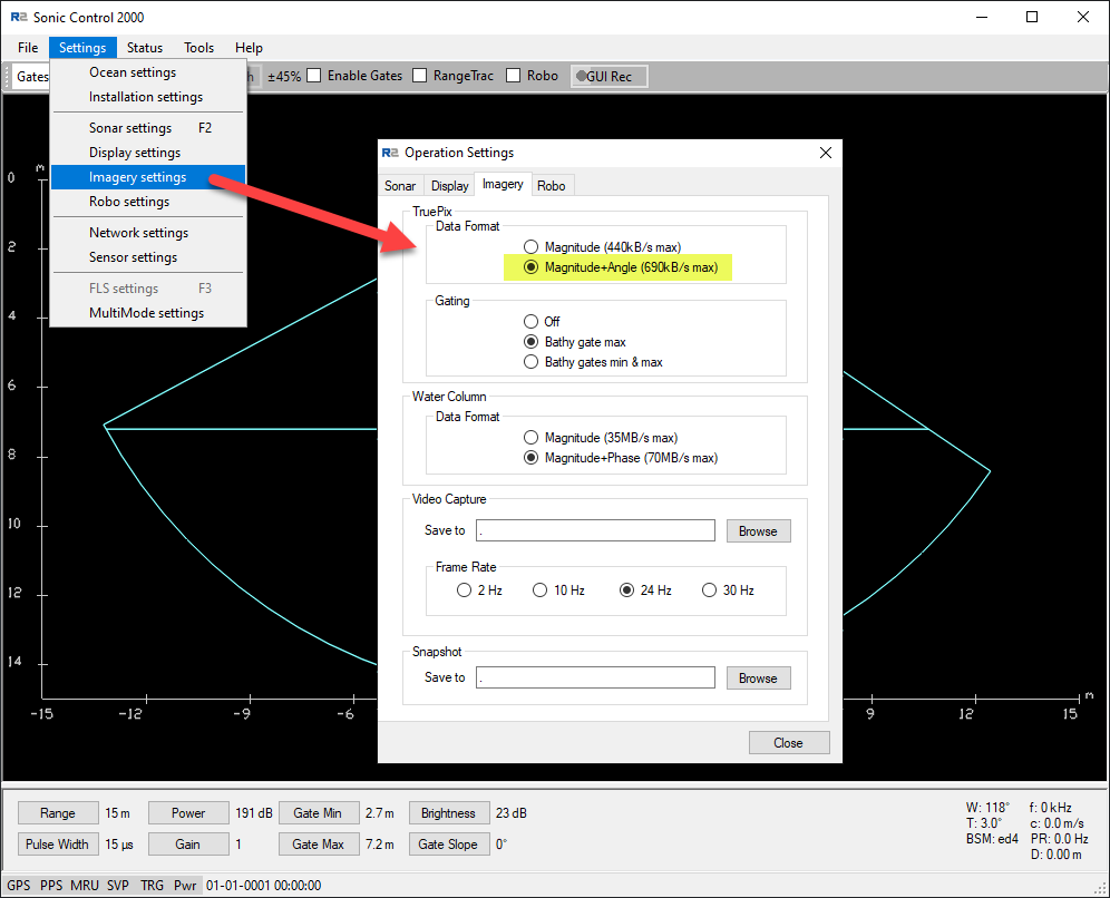
Truepix
In Qinsy Truepix is treated as a Side Scan Sonar. As of QINSy CD version 8.10.2012.05.06.1 the driver decodes TruePix messages (TPX0 packets) and shows them as sidescan data in the waterfall display.
It is also possible to log the raw TruePix messages in the *.db files. (Refer to R2Sonic 202x-Series: Required SSS Raw Datagrams and Qinsy Setup )
Tip
There are two types of Water column data packets: Magnitude only and Magnitude and Phase. The first will induce a data output rate of 30 MB/second and the last an output rate of 70 MB/second.
We currently advise to use Magnitude only to save disk space. If you would like to store the WCD data in a database make sure that your hard disk is fast enough and even consider buying a solid state Disk (SSD).
If you would only like to see the imagery in a raw display then you can just disable the water column storage in the Controller's Session Setup.
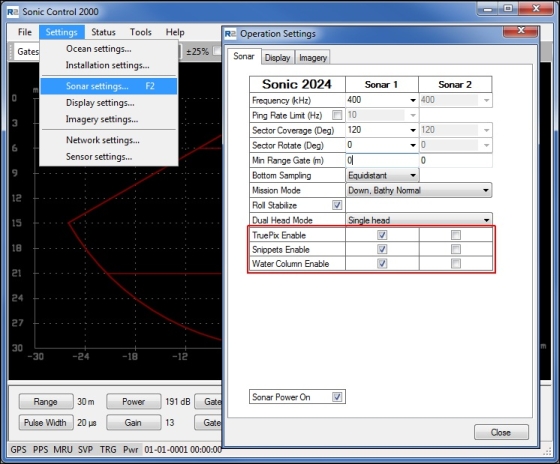
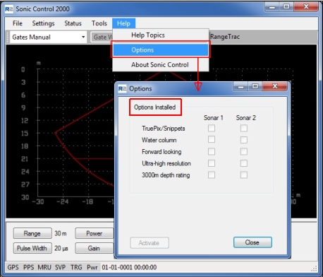
As from the April 2012 build of the R2Sonic Control 2000 software you can select the required output in the user interface and check the installed options:
Port Setup in R2Sonic Control Program
Note that as of March 2013 the driver will automatically determine and open the actual UDP ports.
So make sure to set the output UDP Base port in the Sonic Control program to the same number (e.g. 4000) for every data type!
-
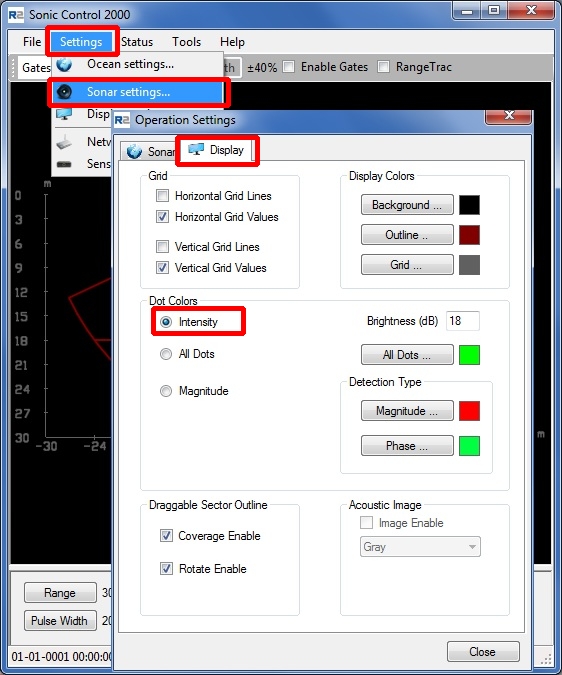
Beam Average Intensity
If the sending of Intensities is enabled in the R2Sonic 2000 control software (see picture below) then the driver will decode the Intensity Beam Average value as the backscatter value per beam which can be stored in a Sounding Grid layer (see Online section below).
To activate data storage see Driver Specific Settings below.
Info
-
Please refer to the R2Sonic documentation for Datagram format descriptions identifying which parameters are stored in each data packet type.
-
Please refer to the Drivers Manual - R2Sonic 2000 Series for system details and configuration settings. (Link only available when logged in to the QPS website.)
DbSetup Driver Specific Settings - MB System Wizard Page 2
R2Sonic 2000-Series (Multibeam)
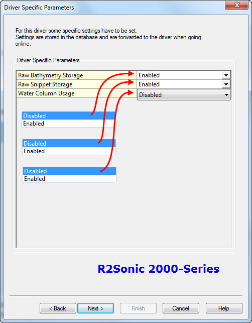
Select the driver specific settings. These supersede the command line parameters and XTF options that where used in the past.
The following settings are selectable for the Multibeam system:
|
Setting |
Option (bold=default) |
Description |
|---|---|---|
|
Raw Bathymetry Storage |
Disabled |
Only the decoded (raw) multibeam data is stored. Online the data can be used to fill a navigation grid and it be viewed in a Raw Multibeam Display and a Swath Display |
|
Enabled |
Both the decoded (raw) multibeam data and the original Raw Bathymetry packets (e.g. BTH0) are stored in the database for usage in Fledermaus and Export to 3rd party formats like XTF. |
|
|
Raw Snippet Storage |
Disabled |
SNP0 messages are not decoded and not stored in the Qinsy DB files |
|
Enabled |
The Snippet message (SNP0) is stored in the database. Online the data can be viewed in a Raw Multibeam Display and it can be used to fill a sounding grid on the fly.
As it was Icon In the past Snippet data were stored as part of the Side Scan system data but this is now part of the multibeam data. |
|
|
Water Column Usage |
Disabled |
No WCD data can be displayed in the Raw Multibeam Display. |
|
Enabled |
The WCD is decoded by the Driver and can be displayed in the Raw Multibeam Display The STORAGE of the water column is activated with a setting in the Online Controller - Session Setup - Database page. |
If you would like to use the Water Column Data then make sure that the setting "Water Column Usage" is set to "Enabled". If the R2Sonic outputs WCD0 messages this will make sure that they are decoded.
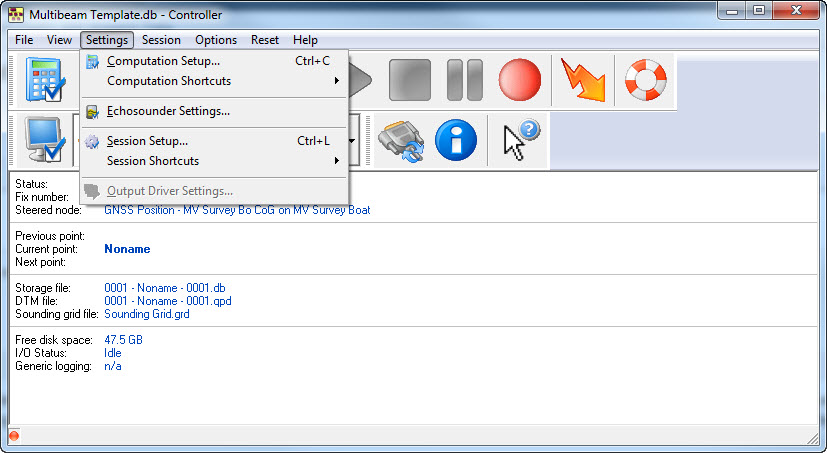
Online Settings
Additional settings are required in the Qinsy Online Controller to ensure the correct sonar data is recorded. These are found in the 'Settings' menu:
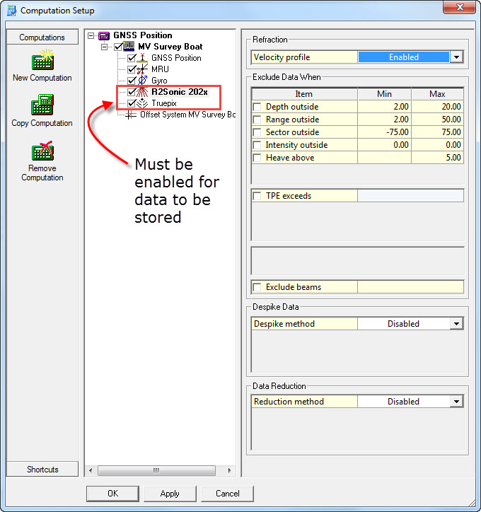
Computation Setup
Make sure the Multibeam System(s) (and Sidescan System for R2Sonic Truepix) are enabled in the 'Computation Setup':
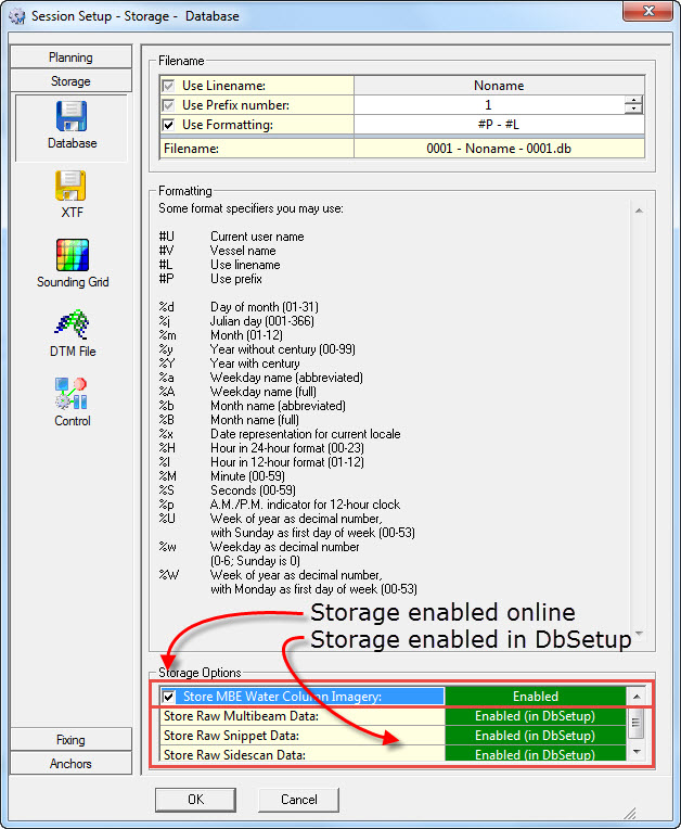
Session Setup - Storage
From the Controller Settings menu select Session Setup. In the left panel of the window that opens select 'Storage'. Data can be stored to various file formats.
Database File (*.db)
Click on 'Database'. At bottom right, sonar Storage Options are listed. Only those systems which were enabled in DbSetup while configuring the template database are shown here. If not shown, go back to Database Setup and check the Multibeam System definition.
Water Column Data
Even though decoding of water column data is enabled in the template database there is still a requirement to enable storage of this voluminous dataset in this window:
Hard disk strain
Storing all the raw data online will put a great strain on the hard disk especially when water column data is enabled. On older computers the hard disk may not even keep up with the amount of data offered to it.
This can lead to excessive buffering in the so-called 'DbOut' driver that writes the database; eventually a warning message in the Controller will be displayed and force a stop of the recording.
If in doubt on the hard disk performance, check the 'DrvDbout.exe' process in the MSWindows Task Manager and check that it is not using too much memory.
Typical memory usage should be around 30-100 MB. If it is increased way beyond hundreds of Mega bytes and continuously increasing, it is possible that the hard disk cannot keep up. Stop recording and see if the amount of memory usage drops again.
As a temporary work around you can stop using the sounding grid, or make the sounding grid cell size larger, or even stop the logging of the QPD file.
Real time storage of XTF files
Storage Mode:
Select Enabled as the storage mode.
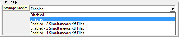
If there are multiple Multibeam or SSS systems defined in the Template database it is possible to create multiple XTF files. Please consult the online Help for more information.
When a single XTF file is used the file name is the same as the associated database (*.db) file except that the extension is 'xtf'.
If multiple XTF outputs are enabled the file name is the same as the associated database (*.db) file but the XTF file extension s are 'xtf1', 'xtf2', 'xtf3', 'xtf4' .
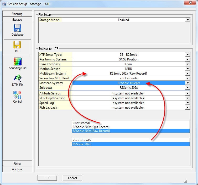
Settings for XTF
Select the XTF Sonar Type. This information will only be written in the header of the XTF file; it doesn't influence the data itself. So when the system is not in the list, choose '00 - Default'.
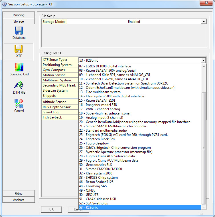
Select all the Systems to be stored in the XTF file. For Multibeam System (and Secondary Head if applicable) select the type of record to store.
[Qps Record] System stored in Qps Multibeam record 28. This 'non-raw' data is drawn from decoded fields stored in a proprietary data container (*.db).
[Raw Record] System stored as raw. Data drawn from 'raw' data packets.
As a reminder of the difference between 'raw' data and 'non-raw' data refer to How-to Raw Bathymetry and Imagery Data
The format contains some generic record types for which the internal QINSy database records can be translated directly to XTF records. For these records the storage of raw data blocks is not required.
For example: Position (XTF_HEADER_POSITION 100), Attitude (XTF_HEADER_ATTITUDE), QPS SBE(26), QPS MTX(27), QPS MBE(28), Sidescan Sonar (0).
However, most record types as specified in XTF are the original raw records being transmitted by a multibeam echosounder, e.g. raw R2Sonic bathymetry packets, R2Sonic Snippet packets etc.
Note
Position and attititude / heading are stored in record type XTF_POSITION and XTF_header_attitude respectively. The other sensors are stored in various fields (XTF_PING_HEADER).
The XTF files is stored in the \Database sub-folder of your current Project folder.
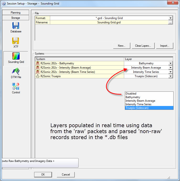
Real-time Sounding Grid
For real-time visualization of bathymetry and sonar imagery, or to produce a gridded dataset on-the-fly as end DTM product, ensure that the different data types are enabled and stored to separate layers in the sounding grid.
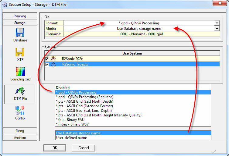
DTM File
DTM data is motion and heading corrected geo-referenced footprint data from an echosounder (multibeam, multi-transducer or singlebeam) or laser scanner system.
Various storage formats are available for output, ready for import into processing software (Validator, Qimera, Fledermaus), or other third party programs (Terramodel, CARIS, Cyclone, etc).
|
File |
|
|---|---|
|
Format |
Select one of the supported formats from the pull-down menu:
*.mbes - Binary WSV - A special format for clients working in Germany. |
|
Mode |
The mode determines the name of the storage file:
|
|
Filename |
A preview of how the file name will look. |
Return to How-to Raw Bathymetry and Imagery Data